| |
-
-
Interesting thinking, unbolt the bonnet/hood and bolt a train body in it's place..
I wonder what other styles of body could be bolted on?
-
Great photo's Norm, thanks for posting them
Of course I'd happily take all the Wh's home, and that superb Super 4 as well
-
Thanks mate, good of you to notice
Hi Paul, mad it certainy will be
Loopy and inventive... Sounds like the perfect combo to me
It's been a very busy and heavy week, but when needs must..
The Volvo engine bay now looks like this..
Engine out..
A big thank you to Rob (far right) who has put a lot of time in over the past 7+ days to help me get this stage done.
A thank you to Matt (far left) who did the very careful forklift driving to pull the engine and trans out..
And a thank you to Nigel (middle) for offering advice, getting in the way sometimes, and for sitting on the forklift to make it look like he did the driving
Back in the workshop with a few parts plonked in place..
Only roughly plonked as the pallet is getting in the way and the engine is leaning to one side.... But you get the idea
To make the engine run a few wires are needed....
Quite a few as it happens.. I need the complete loom from the engine bay back to the front doors.. Which looked like this once the dash had come out..
The fuse and relay box! I won't be needing all of them thankfully!.
Why so many wires? Well, being a "modern"-ish car I need one of these brains to run the fuel injection system..
And one of these which is engine management.. I've not opened it up yet to check, I have a feeling it's one of the ECU's that can be "chipped" to get the engine producing the power it should be rather than the "tamed back" from the factory as it is now..
The loom out the car! I won't need about 75% of this as I won't be running power window, rear screen heater, power sunroof or even the headlamp wash/wipers!
I think I'm going to need a very good wiring diagram
But I do plan to use as many of the guages as I can..
The Volvo now looks like this and is ready for the "metal monkeys" (as I call them) to come and collect.
Parts removed..
Engine, trans, wiring loom...
Propshaft.
Four wheels to smoke the tyres/tires off of
Rear axle..
And a new bit of wall decoration
-
Morning all, well Project Wheel-Vo has taken a big step forward this week as the new running gear has been found...
You might say it's been safely kept in this big metal box
A "can't quite get he's head around my thinking" Nigel gives the Volvo 940 2.3 SE Turbo a
That's quite a big 4 pot!
A Volvo B230FK if your into engine numbers.
Here's the important bit... The turbo
Size wise a manual gearbox would be smaller, but an auto does make life easier... Also I kinda like the idea of being able to keep both hands on the steering wheel during launch as well
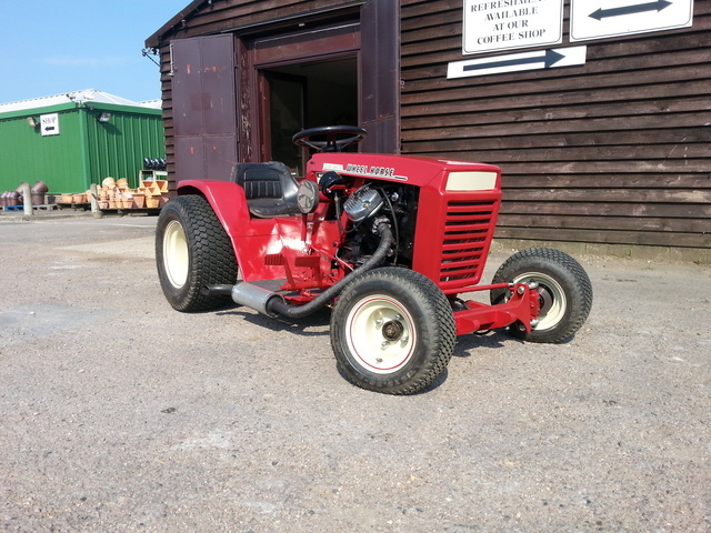
I dug out the WH 312-8 bonnet/hood to have a look size wise......
This pic makes me look totally nuts for even thinking of this project!
However, lift the bonnet/hood up and plonk the said WH item on and suddenly the engine does not look that big..
A certain amount of errr... "Scaling up" is going to be needed on the WH panels but not as much as I had 1st thought as the actual auto box isn't as long as I had 1st thought.
Of course I have to fit a radiator and intercooler under the hood as well.
I will be using the Volvo rear axle, they are known to be strong and (quite handy for me) easy to narrow
As of yesterday here's where I have got to..
Just need to disconnect the shifter linkage, speedo cable (I think the speedo is driven from the 'box), unplug any electrical bits, unbolt the propshaft, unbolt the 'box crossmember and then the engine and trans can be removed as one..
Glad I have the use of a forklift
No idea why the forum software want to put this duplicate pic in at the end, but I can't seem to get rid of it!
-
This was about four cars in front of me yesterday, as luck would have it the traffic lights changed just in time for me to jump out and get a quick snap..
It's not everyday you see this sort of thing on the road
A closer up..
-
A man of many skills, top work there Neil
-
That's a nice haul Paul, they will fit in well with your collection..
-
Cool photo's Norm, I was lucky enough to watch moorhens hatch a few years ago.. From hatching to in the water in under 10 mins! Amazing to watch..
Very chilled
-
That's a very nice lathe upgrade Chris, the Myford will serve you well..
-
The bearing holder was drilled and a tapped so the two bit's could be bolted together..
A clean up on the lather later and the bearing was pressed in..
I couldn't of been happier with the fit of the bearing
Fitted.. Just out of view behind the holder is a couple of tack welds just to hold the holder in the right place.. and yes the spocket is free to move at the moment as I don't know quite how far up/down the shaft it needs to go.
Now onto the fun part.. Getting the 90'd drive in the right place..
Which is where the bit of angle that is bolted to the drive will come in handy.
If you look behind the air filter you can just see 3 more bit's bolted to the drive case..
The go up and get clamped to a couple of bit's of box.. This will hold things steady and give me enough adjustment to adjust it's postition.
But before I square the drive up I need to make the last bit of the drive puzzle and fit a sprocket and bearing to the hollow shaft that's coming out of the drive..
That should keep me busy tomorrow
-
Where were we? Oh yes, making a bearing holder..
Some more turning later and half of the bearing holder was just the right size, a nice tight fit that will need gentle press pressure to push it in.
No idea why these photo's are being turned sideways when I upload them, but anyway here's half the bearing holder and a blank other half.
Both sides done.
The four holes in each half are there so the bearing can be punched back out the holder should needs be..
Time to fit the bearing... Almost..
As the holder will have to be taken on and off MadTrax many many times, and a bit of drilling and grinding going on, rather than fit the bearing and risk it getting full of nasty stuff I made....
This fake bearing
With a little bit of trimming to the inside half of the bearing holder a test fit was in order..
It's rather tight on one of the engine mounts, but it fit's
Looks like the sprockets can be made to line up
Now the big one... Will the shaft from the transfer box to the front fit without hitting anything and how tight will the UJ angles be?
It fit's and the UJ angles are well under 33'degrees, if I remember right the rear UJ angle is about 12'D and the front is a tad over 20.. Much better than it used to be
It's tight but there is plenty of clearance
-
Morning all, time for a long overdue update.
To try and keep this in some sort of time order we had best start with a video..
-
Great photo's Norm, thanks for posting them.
The museum looks good, a nice selection of machines..
I've alway wanted to go and see the Falkirk Wheel, amazing engineering!
-
Sorry for the late reply Koen..
The 850 engine I understand does bolt to a rear wheel drive gearbox, but the wiring would be a total nightmare!
-
That's handy to know should I need to get new gearbox seals
Nice work Chris, the speed your going your have the Raider finished in a month or so
-
That's a cool find Chris, can it lift a whole WH off the ground?
-
It's good to see the little Gutbrod being worked, a great view too..
-
Morning all, a small update for ya..
I have been mostly spending a lot of time at the lathe turning down this, boring out that, and trueing up the other.
Not that many photo's but this was quite interesting to make out of two parts and a bit of welding.
It's not quite finished in the photo, only a bit of tidying to do..
A bored out sprocket is a nice tight fit on the shaft.
Not the fun part, making the 90'd drive thingy fit in not much space..
It's in there somewhere!
This view might help to see what's going on.
The plan was to fit this sprocket to the shaft that comes from the Honda gearbox..
And put this bearing at the end to hold things steady..
The trouble is, not enough space, the drive shaft to the front takes up a fair bit of space too!
Soooo... The plan now is to mount this bigger bearing a lot closer to the gearbox case and fit the sprocket on the end only much more forward than it was..
Of course I don't have a bearing holder for the bigger bearing!
So a bit of thick steel slicing..
Cut's well for a £10 power saw
An almost flat plate.
Flat and mostly bored out..
And that's about as far as I've got at the moment, all this making "one of" parts does take it's time..
But where would be the fun if I just bought everything and bolted it on?
-
Thanks Chris, I've got mine.. Both of them!
I don't have anything to take at the mo, but I do have a plan
-
Ok, maybe that wasn't such a short-ish break
Back to the rear light box..Some of the welds down the sides needed a few extra blobs of weld to tidy them up..
The front edges needed a bead of weld to fuse metal together.. To make life easier I clamped on a flat brass bar to weld against as welds will not stick to the brass..
As you will of noticed on the above photo the longest which is also the top panel is a little on the wonky side..
A big thank you to Rob for the square which came in handy for showing how wonky wonky is..
As the metal is too stretched to hammer flat some extra straight strength needs to be added..
Starting with a strip of double skinned steel.
Most of one skin was cut away leaving only a small rolled edge sort of thing.
A quick trip to the sheet metal folder which I should use more than I do!
Plug welded inside.. The bit of black box section is only to make sure everything clamps down flat..
Can you spot a slight problem here?
Yep, the box is such a good tight fit it won't come back out again!
The next step was to make some mounts for the rear light, but a parcel turned up containing these sprockets
The rear light is going to have to wait, getting the drive train finally finished needs to come first..
Soooooo, the first sprocket on the lathe being bored out to a larger ID..
And that is this thread upto date again..
Hope your all enjoying the build
-
Morning all, time for another long overdue update..
Not having the sprockets at this point I was scratching around for something to do on MadTrax, so I thought I'd continue with the rear light..
Starting with this not quite flat steel sheet. By not quite flat I mean the sheet has had a big cross pattern pressed into it which I though would be good for the back of the light box..
Marked out ready for cutting.
Lot's of chopping, welding and weld dressing later I had this.
The cut out at the base is so the box can fit over the anit roll bar tube.
These ar the buld holders I will be using..
This ally plate is the right thickness to hold the er.. holders nice and tight, so five holes and a bit of cleaning up later..
To mount the bulb holder plate to the inside of the light box but leave enough space behind for wiring etc I made one of these..
Captive nuts welded on the back.
A quick bulb test fit.
Curved panel made to fit the anti roll bar hole..
But before it was welded on the bulb holder plate was plug welded in..
Checking the bulb holder still fit.. They do
A view inside.
Lot's of welding and weld dressing to do..
That looks better
Best check it still fit's MadTrax!!
It does
More to come after this short-ish break
-
As I don't have the sprockets yet (they will be ordered once I've finished this update) and most of the jobs left to do involve having the 90'd drive in place, I was scrathing around for something to do on MadTrax, so I decided to sort this little problem out!
The problem being it should fit here (the tape is only to keep the dust etc out), but I don't have a key for it!
But I do have this tank from a Honda CX trike with a locking cap... I feel a bit of tank slicing coming up
It would of been a shame to scrap the fantasic art work...
So I now have some more wall decoration
The filler hole section was cut from the CX tank, cleaned up and tried for size on MadTrax's tank.
To mark where I would need to cut on MT's tank I needed to cut out a small section so the new bit would sit flat..
And here is the very same hole after being part welded back in! Yes my brain wasn't functioning to well that day and I cut too much out!
The correct size hole marked and cut out..
A test fit, only a few little tweaks needed..
While I was getting on with the welding Rob was cleaning all the paint off the locking cap thingy.
Quite a few layers of paint!
Ta-Daa
As you can see with the flap open it needs a little bit of filler work.. Not much though
I gave it a quick coat of paint to help show up where I may of missed any welding... Here's one of the holes.
The new cap looks the part, I can't decide if it needs painting of just a coat of matt clear coat.. Time will tell
-
Morning all, sorry I've not been on MOM in a while, life has been er... Interesting shall we say!
Anyway, an update for you..
Plenty more lathe work to go, I needed to make something that would fit over this stepped shaft on the TB input side of things.
The reason being I need to fit a sprocket to the shaft but there isn't a keyway for location, only splines at the outer end.
Lot of time was spent with some 40mm bar to create this.
Outer splines presure fitted to the sleave one end, it will be welded also.
Stepped inside to fit the shaft. It would of been nice to cut a taper inside to match taper on the shaft, but don't have the tools to do it..
Splined sleeve bolted on the TB shaft, the sleeve walls are not thick enough to cut a keyway so the sprocket will have to be welded on.
Back to the 90'd drive thingy from the Honda Silverwing that I'm using to turn the drive around..
On the bike the rear wheel would of bolted to this bit.
But I need to put the drive from the gearbox into the 90'd drive from this way... But how to bolt a sprocket to it?
Starting with a slab of 10mm thick steel and a photo that won't turn the right way!
To bolt the splined bit flush on the plate I had to cut a wide groove in one face.
That looks good.
To fit a sprocket to all this a shaft is needed.. This will do.
It fits in the circular plate like this, the tapers will be filled with weld.
The other side will get welded on and the welds turned down to look good on the lathe.. The shaft has been made over sized as I don't know the measurements until I get the sprockets and try to fit the whole thing in place.
This is quite a big "whole thing" to fit!
-
Thanks for all the birthday wishes guy's, much appreciated
Saturday was a very quiet day, which was very much needed after not the greatest couple of weeks.
|
|