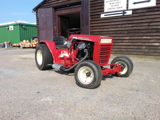
Morning all, no progress has been made on Wheel-Vo at all in quite a while, all the parts have been carefully stashed away until I get MadTrax finished, but some thinking has been happening..
The nice slot mags that came from a CX trike a long long time ago were dug out to see how they looked..
Me rather likes
To get the wheels to fit the Volvo axle I'm going to have to make a pair of wheel adaptors as the PCD on the wheels is a lot bigger than the Volvo PCD..
The trike the wheels came from was running (we think) an Escort rear axle using these adaptors to get the wheel to fit!!!
The thought of putting any power through these is scary to say the least!!
But as luck would have it I did make a start on a pair of wheel adaptors to fit these very wheels onto Project Why Not which saves some work although there is still plenty of lathe time needed to finish them..
When I start back on this project the first job is to tempoary widen/lengthen/make a bit taller all the panels until the "upscaling?" looks right and of course the engine and other bit's are covered by the bodywork..
Then I can start measuring for a chassis and try to work out how to get suspension under the thing..
No suspension (like Why Not) would be easier, but Why Not gave my body such a hammering that I don't think plonking a cushion on seat would be enough
Progress has been rather slow, a lot slower than it should be, but life, illness and having a workshop full of wood tools (don't worry, I havn't given up on metal and turned to wood, most of the wood tools have gone now) has slowed things down.
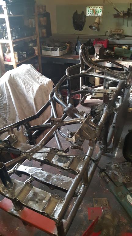
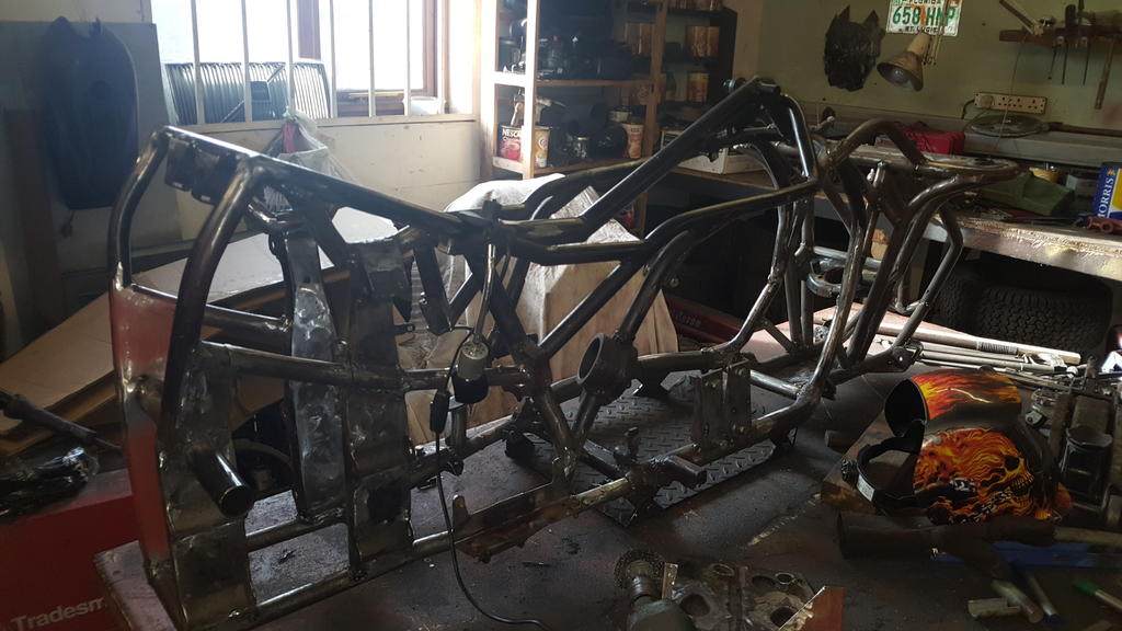
Life on MadTrax has been grind, weld, grind, weld, chop some metal off, weld nwe stuff in, grind, weld..... you get the idea.
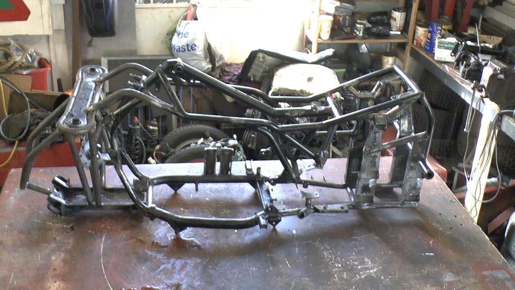
The frame has spent most of it's time on one side or the other and even upside down at times!
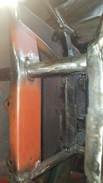
I think in this photo I was adding strentghening to one of the transfer box mounts on the frame.
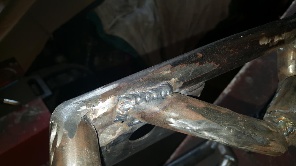
A lot of my "earlier" welds on the frame were done before my Murex Mig welder had an overhaul and a new gun...
And it showed on the welds!
So a lot of time has been spent grinding out bad welds and replacing them with good welds like this.
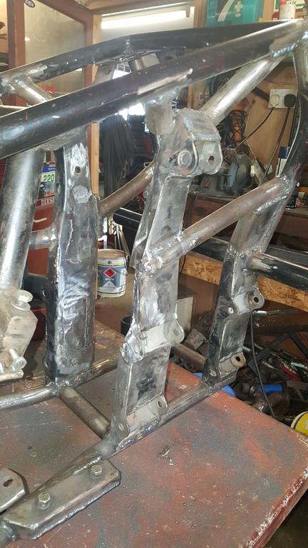
The pressed steel rear suspension uprights had the outside boxed in a long time ago, the inside has been done now..
Cleaned up with a touch of red oxide..
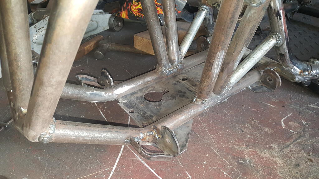
You may remember this orrible bit of Quadzilla frame that was at the front..
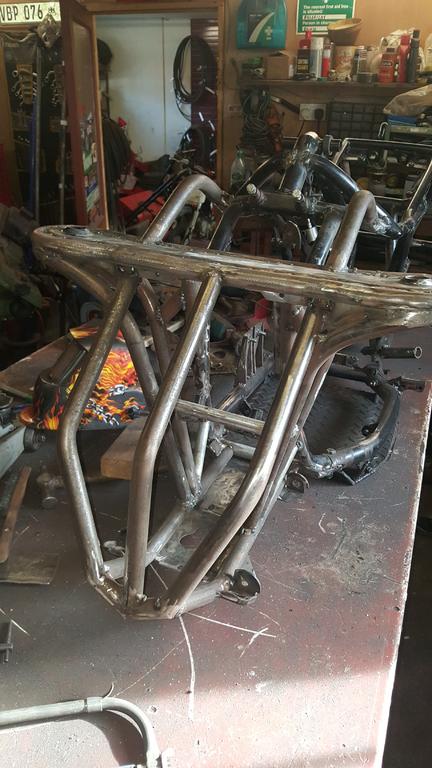
Well, it has been cut out and replaced with some nice tube to match the rest of the frame.. Looks way better
A couple more views..
The engine guard has come in very handy when the frame is the right way up, it keeps the frame upright and makes it very easy to turn around on the bench..
That's all the photo's I have for now. I have slowly been working from the back forwards and have now reached the point where I just have to finish off bit's infront of where the engiine should be..
On the next build I will try and fully weld up everything as I go along... I've had to do so much "finishing" welding and grinding it's quite soul destroying!
Your doing a great job there Chris, from a pile of rusty parts to someting far more red and shiny
I snowblower has always been on my want list, but if the past 6 odd winters are anything to go by, I'm not sure Hawkhurst would get enough snow to need one!
Reminds me of a skeletal version of a House Robot from the Wars......Dead Metal-ish . Regret not being able to pay a visit yet Ian. Hopefully in the near future.
Hi Richard, hope your keeping well..
Robot Wars eh... It's been a long time since I last watched it... Is it still going?
The last time I heard anything about Craig Charles he was/is doing a Funk and Soul music show on BBC 6 Music!
Not that I have anything against a bit of Funk you understand
It would be cool to catch up with you again Richard, no rush whenever is good for you
Now for a fun video
The stripdown should of taken a day at the most, but when everything is being video'd using my Camera Panning Jig Thingy, one day gets stretched to five!
With the frame stripped down I could make a start on the final welding.. Well, almost
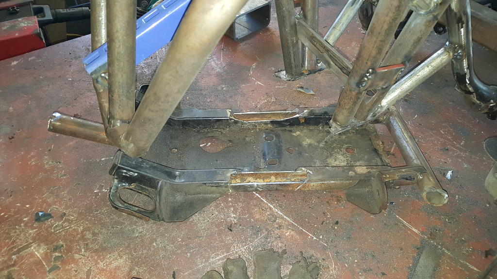
The last couple of bit's of "made out of a cheap office desk" Quadzilla frame were bugging me..
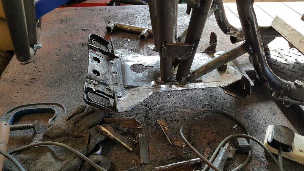
The only problem was important bits such as front suspension lower mounts and front diff mounts are made out of one big plate that's welded to the Quadzilla frame.. And it's kinda important to make sure these mounts stay in the same place.
So after a lot of bracing including something to hold the said plate in the right place, the lower front got the chop!
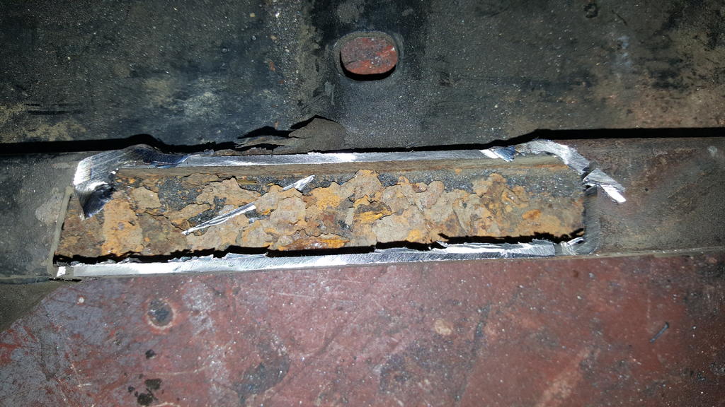
Would you look at the rust in that!
At some point during the build the bit of tube that these two bit's of desk are attached to was welded in not quite where it should of been.. In other words it looked pished but wasn't noticable until everything had been stripped from the frame!
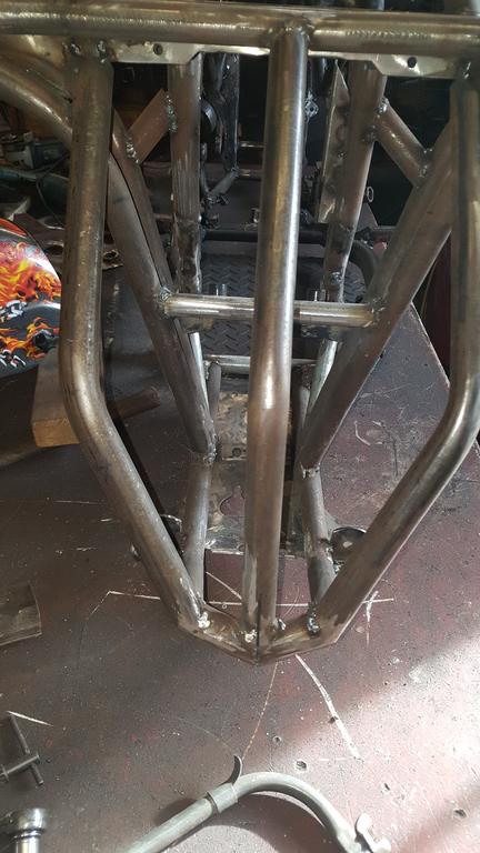
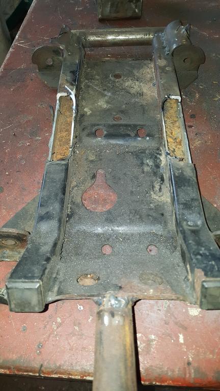
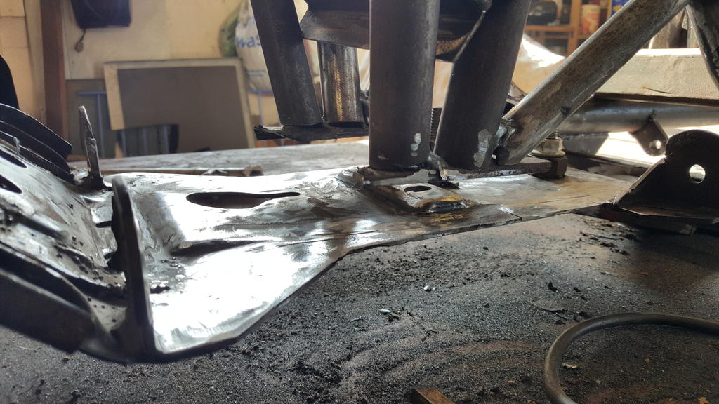
Cleaning the suspension plate of the left over bit's of rusty desk took a while, here's the plate bolted back on where it should be..
A bit of space to fill to connect everything back up again..
A lot of new thick wall tube has gone back in the front, but I forgot to take any photo's yesterday..
Morning all, Wow almost 2 years since I last updated this thread!
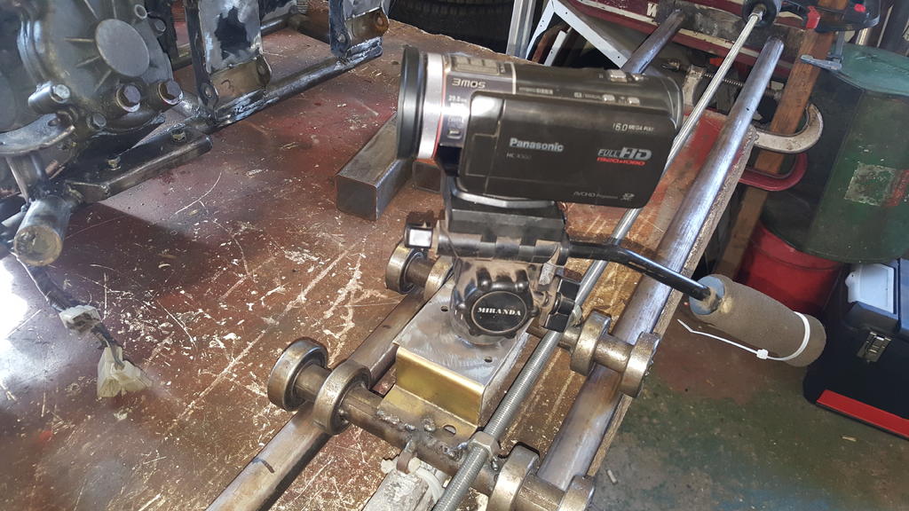
Quite a lot has changed on the Camera Panning Jig Thingy or CPJT for short..
The bearing wheels lost thier inner tube rubber tyres/tires as well, they kept losing them.. Despite a nice tight fit on the bearings they would work their way one way or the other and come off!
String or fishing line was always a bad idea really.. The fishing line was a very strong one, I can't remember now what it was rated at) but it would still stretch and eventually snap!
I didn't fancy it breaking when doing a vertical shot and my video camera hurttling towards the ground at a very fast and very damaging rate
Soooo, now we have a whole lotta thread
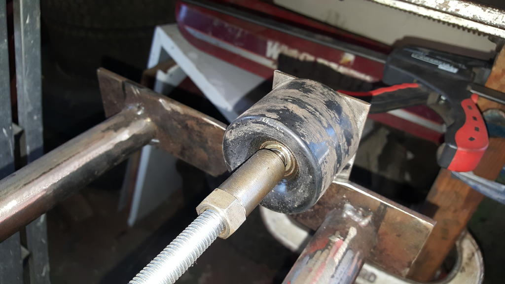
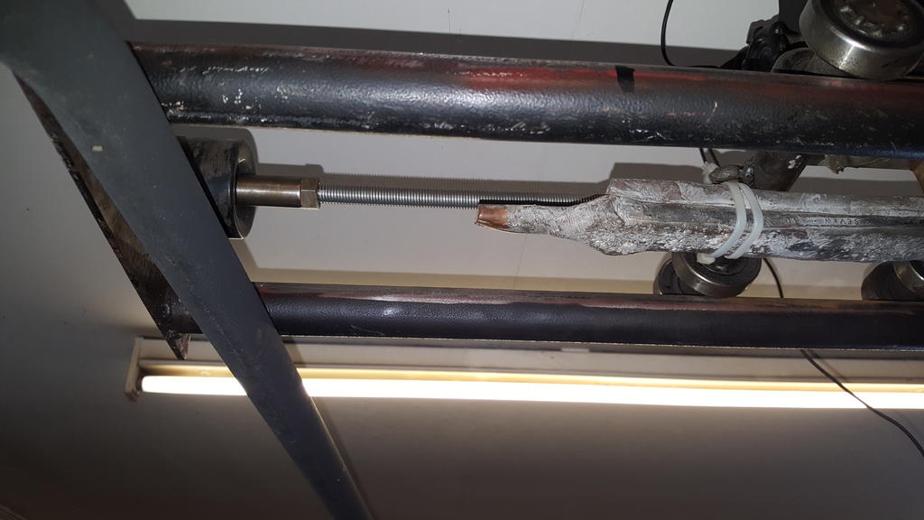
Let's start at the smaller end...
That's the end of a rather long length of threaded rod with a "made on the lathe" thingy that screws onto the rod (with a lock nut) and allows me to put a bearing or two on the end of the threaded rod..
Yes you are seeing correctly, that is a skateboard wheel and bearings fixed on the frame
The idea is the skateboard wheel allows for a little bit of movement which makes everything run a lot smoother.
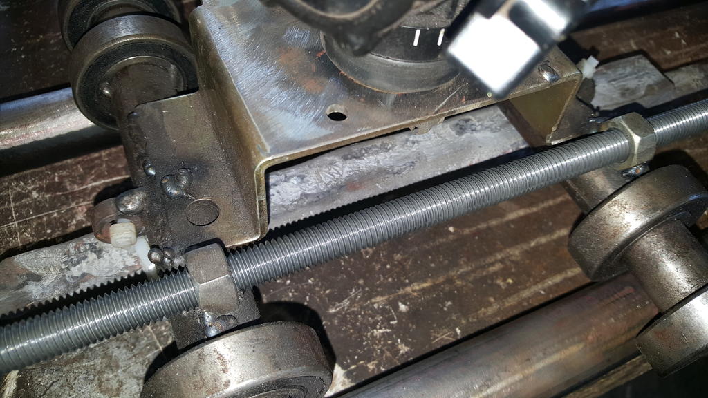
Moving along the threaded rod we come to the camera carriage thingy..
Zoom in a bit and you can see the threaded rod runs through a couple of nut's welded onto the carriage..
As the threaded rod turns, it forces the nut's to wind down (or up) the thread which being welded to the carriage moves the carriage along the rails... Cool eh
A view from the underside.. The lead pipe is zip tied on to the carriage to counter balance the weight of the carriage and camera on top when the CPJY is being used vertically.. Otherwise know as up and down
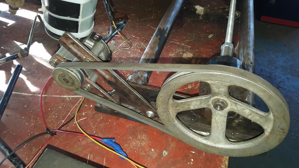
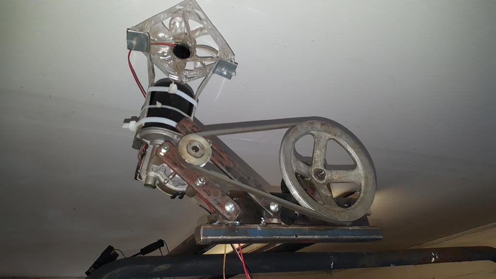
Moving down (or is it up?) to the business end we have a couple of pulleys a belt and half a wiper motor..
With the pulleys set this way the carriage moves down the rails at a ground breaking 1 inch per minute. The carriage has a little over 6 foot of travel along the rails which gives me a 1hr 12mins recording time as the camera pans it's way down the rails..
That may sound like a long time, but is is very handy when filming long scenes such as stripping all the parts off MadTrax
If I swap the pulleys around then I get a total travel time of about 6 mins..
I have made a couple of other pulleys (no photo) which can be swapped in giving more travel time options..
A better view of this end, a computer cooling fan has been fixed on to help keep the wiper motor cool.. It does get a bit hot which I expect it did when it was actually being used as a wiper motor!
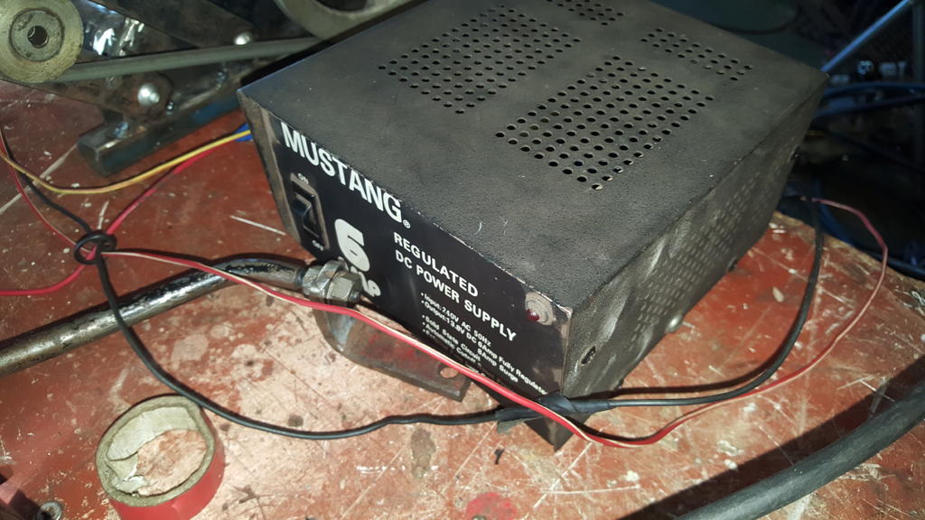
Power now comes from a Mustang CB radio power pack.. No fancy speed control this time (as the pulleys take care of the speed), just forward and back depending on how the two wires are connected.
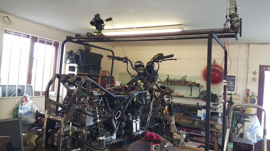
The lengths (and heights) I go to to bring you all good video footage
You can see al the "panning action" in the next MadTrax video, strip down in timelapse
That Rolls crew cab looks great, I'd happly use it every day if I could afford the fuel
11 hours ago, Stormin said:
Is that the one that went up in flames in Sweden if I remember right?
I think that was "The Beast" Mk1 Norm that went up in flames.. If I remember rightly it was kinda based or used bit's of a Capri body?
The Beast Mk 2 as above used to have a Rolls Royce grill, JD on the current grill stands for John Dodd.
The story (of which I expect there are many) goe's, John Dodd was driving The Beast abroad (Spain or Germany, I can't remember) on a motorway and flew past a Porsche at a very high speed..
The next day the said Porsche owner went to a Rolls dealership asking for the new Rolls estate!
This is when RR got the 'Orse about Mr Dood using their grill on The Beast..
The court hearing was in London, so every day of the hearing Mr Dodd drove The Beast to the court in the center of London
I've heard The Beast is still alive and well, now living with Mr Dodd in Spain but it does come over to the UK once a year for an MOT..
Disclamer... All the above is based on on a fading memory and only 2 coffees so far today, so it might not be 100% acurate..
Thanks Norm, it's good to have it driving after all this time.
Soooo, what does it drive like?
Well, very good as it happens.. MadTrax feels very stable and planted with not even a hint of "it's going to topple over"
Oh, and it's fast... In high ratio of course.. Trying to work out the gearing is impossible, so I'm going to guess it will top out about 80mph..
Not that I fancy doing that sort of speed on a quad of course
Off road it's just as good, it feels almost unstoppable.
Rob and I were testing it by driving across deep ruts back and forth.. Eventually it started spinning the rear wheels, flick the switch to 4x4 mode and it pulled it's self out straight away..
Amazingly despite the testing abuse nothing broke! Me happy with that
A few minor little problems to sort..
During the off road testing MadTrax did get rather hot, in a "needle in the red" sort of way!
Part of the problem was an airlock in the cooling system, of course the highest point is where the temp sender is!
As the water level in the expansion tank is no longer dropping I guess all the air has gone out the system..
The other part of the problem is while riding MadTrax, the engine is at high RPM but the quad isn't moving that fast to push cold air through the rad..
So I have got an extra cooling fan to fix to the outside of the rad, it should help things out..
One thing the engine is doing that I wish it wouldn't is it's running very rich!
The carbs have already been cleaned out, so a bit of carb tuning and balancing will be done when MadTrax goes back together..
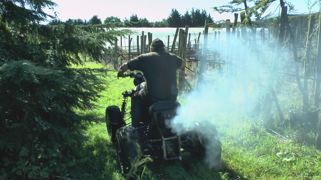
I did try and get some off road video footage, but for some reason I was having a bad camera day and didn't notice the camera was already recording..
So when I hit the "start recording" button to film the action, I was actually stopping recording!
The end result was I had mostly footage of "the bits inbetween" rather than the action!
No photo's other than this screen grab of MadTrax ripping up the grass.. The smoke is from the over fueling!
MadTrax is now back up on the bench ready to be pulled apart tomorrow or Friday.
Lot's of bit's to be "fully welded up", and painted.
Morning all, not sure if anyone is still reading this, but if you are thanks and here's a rather large update for you.
Starting with a video in order to try and keep things in order..
I hope you all enjoyed that..
So where were we?? Oh yes, mounting the bearings that make up part of the drive system to the front.
The original mounts were trimmed back until only the plates with captive nuts were left.
Here they are bolted to the back of the bearings, ready to be tacked onto the frame.
The random bit of angle is there to keep the tops in line.
And without the bearings, just tacked on.
A bit hard to see in the next two photo's, the bearing mounts now have extra strength with gussets added.. As ever not fully welded in these pic's.
The front er... prop/drive/transfer shaft thingy has been welded up, I will be adding some extra rows of weld "just in case" and to tidy the shaft up a bit.
The other end is fitted in place with a tight fitting roll pin.
Oh, if your wondering the shaft does look like it's running true
One last thing to do before the drive system is finished... Attach all the sprockets to the shafts..
Starting with the first and second in line there was a bit of lining up work to do..
Here's No 1.
A close up and you can see the chain wants to bend to the right or forwards if you will.
A bit of extra space between the chain and bearing holder would also be nice..
At the other end of that chain things were also a bit tight between the chain and bearing..
To solve the problem this part came back out for a bit of turning so the sprocket could be moved away from the bearing.
Before welding the sprocket onto the shaft (no space for a roll pin) Rob started toasting all of it..
As both the sprocket and shaft thingy were very cold, both were heated up so the cold metal wouldn't just suck the heat out of the weld.
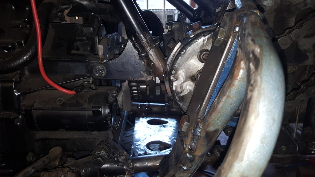
The 90 degree drive thingy out.. A big moment as it means everything will come out of the frame.. Phew lol
While the drive system was out I was able to do a bit of extra welding inside the frame, as some bit's were only tacked together at this point..
For some reason I forgot to take load of pic's of the next stages, so the photo's might seem a bit random..
This bearing holder needed a few mounts.. Two mounts this side..
Making the mounts for this inside was more interesting, I also had to make lower mounts for the big blue bearing..
No photo's of this done but you will see it in the next video.
Chain half links and a sprocket turned up, this is part of the chain tensioner, so the sprocket was bored out to take a bearing each side.
The transfer box idiot light switches were removed as the exhaust would melt them also they are not really needed.
A couple of ally blanking plates blocked the holes back up.
The finished chain tensioner thingy..
I think a 30mm bolt head is about the right size and in no way oversized
I think now's the time to drop in Part 24 of the build videos..
Morning all, well the point of starting MadTrax up and testing the runnning gear on the bench isn't far off..
Time is still lacking but I have made a good start on the transfer box to from diff drive/prop shafts.
I've not taken many photo's and even less video footage as I just wanted to get bit's done while I had the time.
Holding a small shaft in place to measure up and work things out was a right pain until I quickly made this "bit of tube welded to box" which holds the shaft in the right place.
The shaft to the front has been extended and made a slightly bigger diameter to fit the new UJ.. I've not welded the shaft up yet just in case any adjustment is needed.
Here's one of the bearing brackets I made up.. Think it's going to need a lot of trimming now everything is a lot closer to the engine..
Morning all, only a small update I'm afraid, life is still keeping me very busy and I don't see it getting quieter anytime soon!
Not much to show really, but I have been working on mounting the rear brake pedal and cylinder.
Quite a hard thing to photo if you don't have a clear different colour background!
I have fitted the Quadzilla brake pedal, it was originally a flat plate that was bolted to all sorts of places to give it strength.
As I couldn't do that I had to box it in. Here's the other side.
Brake cylinder bolted on.
The whole footrest/brake pedal mount thingy bolted back on.
The rubber hose to the reservoir will sit just under the steel mesh when it's put back on.
The pedal looks like it's lying almost flat, but it's in the right place if you pivot your foot on the end of the footrest which is where your feet naturally fall
I will make a shield that uses the cylinder bolts to add so side protection to the cylinder..
Starting to look a bit busy with the exhaust and driveshaft plonked in place, the propshaft guard will take up a bit more space as well.
And that's as far as I have got photo wise.. I have been making a bearing mount removable and made two of the four mounts needed to go on the bearing that holds the shaft that comes out the bike gearbox..
I will get some photo's tomorrow that might explain it a bit better than I did above
With the above done the time had come to mount the bearing that holds the shaft out of the transfer box up.
Here it is roughly in place, the foot rest thingy still needs a little trimming at this point.
The next four photo's were taken from video footage I took quite a while back, but they are handy for showing a part I had to make.
The end of the shaft in the TB has splines which as we all know have a little play in them.
To hold the shaft in exactly the righ place I make up this collar/sleave/thingy..
Which slides over the shaft and when flat against the plate hold the shaft in the right place.
Skipping forward in time again the collar/sleave/thingy has been tacked in place. Once the bearing is mounted it will be removed.
The old steel mesh was removed from the foot rest (I have some new mesh which matches the exhaust guard) and a nice strong bearing mounting plate welded on.
Oh, the top tube has also been sliced off and welded back on with a nice strong steel bar inside for extra strength.
A view from the back, I need to get a half link to shorten the chain and make a tensioner thingy.
One thing I was worried about was how much the chain would stick through the footrest... As you can see it doesn't stick though at all.. Me happy with that
And that is where I have got too, with a bit of luck I will have more time next week to spend at the workshop..
Morning all, sorry it's been so long between updates.. Life has kept me so busy of late that I've not really been at the workshop that much!
Having got the 90 degree drive thing in the right place, it needed to be mounted strongly.
The curved brackets were made by welding on end to the large bit of thick wall pipe and beating it around with a large hammer while it was still hot from welding.. I thought I had some photo's of that stage but I can't find them!
As you can see it's all only tacked in place at the mo, it will only get fully welded once I know the transfer box etc can actually be removed from the frame! In theory they should, but you never 100% know for sure until you try..
A thrid mount will be going down to the frame but I couldn't work out exactlly where until I had made and mounted a strengthening plate that runs between the frame rails..
Of course I did not have a large enough thick enough bit of steel plate, so I had to make one..
Missing a few photo's here but I had to slice up a Wh 312-8 fuel tank/fender pan mount for the steel..
Clamped down ready for welding.
Leaving a big enough gap to fill with weld.
Weld won't stick to brass so a brass plate was clamped to the underside.. The black bit is ally which works as well, it just burns away a lot faster..
Welded, shaped and roughly put in place.
To mount the plate I knocked up four of these captive nut brackets.
In order to center punch the flat plate in the right place for dilling I drilled a hole though a spare bolt that was only just big enough to get my punch in.. It makes sure the punch mark is in the center of the capive nuts.
Brackets tacked on.
Lot's of chopping and welding later the plate now has some strengthening holes including one just below the odd shaped tube and bit of box 90 degree drive mount so a ratchet can be used to bolt it on..
A pic from the other side with the third tube mount tacked in place.
As much as I would of liked to weld the big pipe into the frame to make it all very strong, I wouldn't be able to get the transfer box out if I did! So I have made up some curved mounts which you will see in the next update..
But while I was at it I thought it maight be an idea to bolt a few bits in place to check everything still fitted..
With a bit of trimming and a lot of strengthening the bearing block can be made to fit flush on to the n/s foot rest which keeps things neat and tidy, but the footrest will need a lot of extra strength added.
I did at one point think I would have to widen the foot rests as the chain, sprocket and bearing would take up so much space.. But with the bearing mounted flush the chain and sprocket hardly poke through at all, also the 90 degree mount only takes an inch or so foot space away from a bit of the footrest that doen't feel a natural place to put your foot anyway..
So no widening needed, just a bit of extra mesh to go over the chain..
Oh, I do have some much better looking mesh to replace the rather tatty looking mesh thats fitted already,
A view of the back.. The chain needs to lose a link and a half and there is plenty of space to put a chain tensioner.
Good news with the o/s footrest as well..
The drive shaft that goes to the front now takes up so little space (much closer to the engine etc) that all I need to do is put a cover over it so it doesn't try and grab my boot laces as it spins..
Plenty of space to mount the barke pedal as well
And that is where I have got to on this build as of yesterday.... We shall see what progress Thurs/Friday brings as I want to spend next Mon/Tuesday having a play with Project Wheel-Vo
Well, morning all. It's been a while since I updated this as pulling apart a Volvo had been taking up most of my time.. Making bits on the lathe for MadTrax has taken a while as well..
Anyway..
A shaft was needed to slide over the splines on the 90 degree drive thingy to get the power out the same side as it need to go in the transfer box.. Here it is on the lathe.
The shaft with the splined bit pushed tightly on the end.. Just needs welding up then back on the lathe for the final machining.
That looks better, turned down to size ready for a bearing on the end..
But how to hold it in the right place for making bearing mountings as we all know splines always have a bit of play in them?
This will do the job
Slid over the shaft.. Once it is tack welded to the flat plate behind it will hold the shaft steady... I hope that makes sense?
Now another fun bit.. A long long time was spent getting the 90 degree drive in exactly the right place.. No mean feat considering it had to be right in so many planes!
To make sure it stayed put, the tempoary mountings (bit of angle) were temporarily tacked in place..
Nice one mate, another red project to get your teeth into
Not this time mate...
Well, the C-101 is no more..
As well as needing a bonnet, fender pan, carb, seat, starter motor, I found out that the main body tub was so rotten (most of it just pulled apart sort of rotten) that the poor C went from project to breaker for parts with the funds going towards the latest project..
Sorry guy's, sometime you can't keep em all..
Oh, if anyone needs any "C" parts that are not engine, trans or bodywork let me know
This is going to be a crazy build! Looking forward to it
Thanks mate, yep crazy it certainly will be
On 13/06/2018 at 9:41 PM, C-101plowerpower said:
dont think those front wheels will be on the ground alot absolute madness, i love it
Hi Koen, it will be interesting to see what the front end does under power.. The brain says the front wheels should lift, but.... at least 75% of the weight will be at the front, so..... ???
Let's start this small update with a video shall we?
To keep Nigel happy, here's a pic of him actually driving the forklift as the engine was moved from a pallet to a four wheel'd trolly thingy.
Though I think the forklift fumes may of gone to his head a bit
With the pallet out the way we could plonk parts in more or less the right place..
For the comedy value the wheels were put where they would be on a standard WH... A bit narrow me thinks
I like this view, with the wonky wheels and panels it kinda looks like a wacky cartoon
I'm trying to be good and get MadTrax finished before I start on this build, but you just know I have to have a fiddle and make a start even if it's only getting everything in the right place so I can take some measurements..
A lot to work out first before I can even think about making a chassis!
And to finish this update, have another video.. Wheel-Vo part 2.


")


Project Wheel-Vo... The Build has Finally Started!
in Home Built Items
Posted
Morning all, no progress has been made on Wheel-Vo at all in quite a while, all the parts have been carefully stashed away until I get MadTrax finished, but some thinking has been happening..
The nice slot mags that came from a CX trike a long long time ago were dug out to see how they looked..
Me rather likes
To get the wheels to fit the Volvo axle I'm going to have to make a pair of wheel adaptors as the PCD on the wheels is a lot bigger than the Volvo PCD..
The trike the wheels came from was running (we think) an Escort rear axle using these adaptors to get the wheel to fit!!!
The thought of putting any power through these is scary to say the least!!
But as luck would have it I did make a start on a pair of wheel adaptors to fit these very wheels onto Project Why Not which saves some work although there is still plenty of lathe time needed to finish them..
When I start back on this project the first job is to tempoary widen/lengthen/make a bit taller all the panels until the "upscaling?" looks right and of course the engine and other bit's are covered by the bodywork..
Then I can start measuring for a chassis and try to work out how to get suspension under the thing..
No suspension (like Why Not) would be easier, but Why Not gave my body such a hammering that I don't think plonking a cushion on seat would be enough