Anyway at closing time Gilbert had flaked out on the bar stool with his head in the ashtray after every one had left the land lord woke him up and walked him to the door and layed him on the bench outside locked up and went to bed, about 3 in the morning Gilbert woke up again. Freezing his bollocks off and soaking wet, it was pissing down now it was a 2 mile drive up the narrow lanes to get back home, so Gilbert started the tractor and set off, still completely pissed, anyway he got about half a mile up the road zig zagging all the way then he spotted the gate on his left hand side and remembered as a young lad he used to cut through there on foot and across 2 fields would bring him out home so off he went round the outside of the field driving into the blackthorn hedge many times, into the second field and strait into the duck pond right outside the cottage his mrs was living in with the batty girl he fell of the tractor it over turned and crushed his pelvis and smashed his hip the 2 girls heard his cry and rushed out the house in just knickers and bra and managed to pull him out, gertroid the batty girl called the medics who turned up with sirens blaring and blue lights flashing they couldn’t believe there eyes what was in front of them, two fat birds in there under crackers tending to a pissed bloke that looked like a porcupine and claret every where, anyway back to the hip joint coz I always took the piss out of him my dear old uncle Gilbert left it to me in his will, he died of a broken heart, and that’s why it’s a sad story
A real sad story there mate, it brought a tear to my eye
Well, a bit stuck on the drive train at the mo.. The Honda Silverwing final drive/90 Deg thingy I was planning on using just won't work!
I did the maths on sprocket sizes to work out the 5 - 1 ratios I would need and the big sprocket would need so many teeth that it would be nearly a meter diameter!
Price wise it would be very much the wrong side of £1000 and the sprocket would be so big it would cut the quad in half!
So.. some more thinking needed.. I need a strong 1 - 1 ratio 90 Deg drive that will fit in the rather small space available!
Sooo... What to do next.... Some welding me thinks
At the back where the new tubes meet the Quadzilla suspension mounts it looked ugly as I had just cut the tops of the mounting panel off..
A bit of cutting and welding later had a couple of bits of box welded in just above the anti-roll bar tube.. That looks better and stronger
Part of the plan has always been to box in the pressed steel suspension mountings as I hate the look of pressed steel, and they never looked strong enough anyway
Starting with one of these, a bit of tube with washers welded on both ends.
Which happens to be a perfect fit inside a thicker bit of tube that has been cut in half..
Bolt it to the suspension mounts and you have an ideal way of making sure all the bit's of half moon tube fit in the same places..
A bit of tack welding later..
Best check for clearance, plenty of and more travel than will ever be needed
Now to fill the gaps, the top of this speaker stand is about the right thickness
Four plates cut to size and tacked on plus a template for the next panel..
The right side almost done.. A few welds need a clean up, and a few of the welds won't be done until the frame is stripped and on it's side.. I hate welding upside down and I'm rubbish at it!
Best make a start on the other side, templates cut out..
And marked out on steel... It's a good job speaker stands come in pairs
No idea why this photo has turned around, it's the right way on my PC..
As you can see the shifter stick er... Sticks a fair way out from the gas tank.. A bit too far out for my liking..
Before I could narrow it I needed to find out why the stick just fell to one side under the weight of it's self.
Once cracked open I found two springs were missing that that should hold the gear stick in the middle..
Not being able to find any compreession spring in the workshop that were the right length, width and strength I found a couple of bit of clear fuel pipe work just as well
Just over an inch removed from the shifter.. Both halves were V'ed before welding back together to give maximun strength.. It looked quite nice once the welds were ground down nice and smooth
Bolted back on to the frame, but I don't like the look of the shifter knob, it's more "Montego/Maestro" than MadMax, but thanks to Nigel I have something a bit er... Different to graft on...
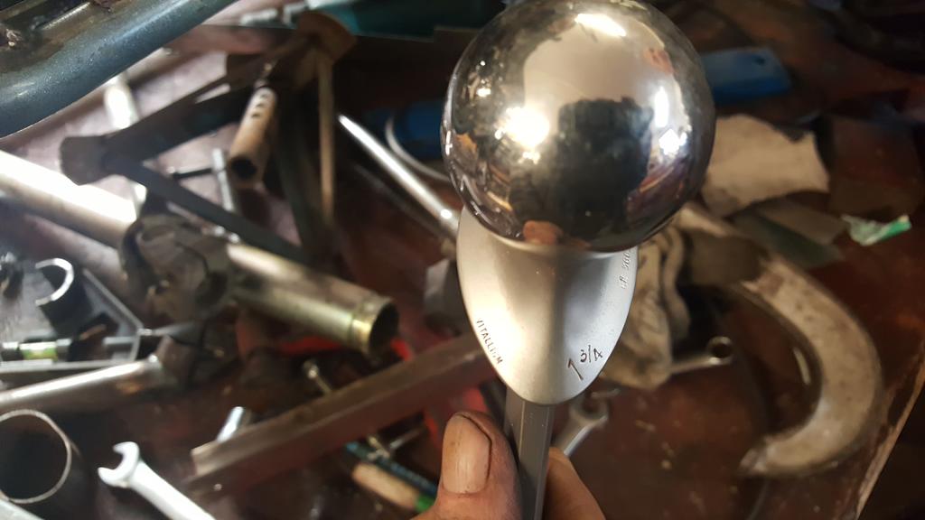
Yes it is what you think it is... A titainium hip joint
Morning all, time for a long over due update, though not a great deal has been happening..
I needed a better looking bracket to mount the transfer box shifter stick as the Quadzilla one was too big and very ugly.
I'm sure you can guess which one is the new one
Shifter bolted in.
Still not quite sure where to mount it on the frame at this point, so I welded a couple of bolts to soe blue steel bar.
Very long bits of bar
With the "bolt ends" of the rods stuffed through the frame and bolted on the TB levers, I could see there was a fairly straight run to connect the rods to a "next to tank" mounted shifter...
But then I found out all the shifter marlarky fitted nice just above the exhaust, tucked into the frame a bit..
Just enough space to get the connecting rods on
With one shifter box mount thingy done, the rods were shortened a bit, had a few bends put in and a bolt welded on the other ends..
It's a bit crude, I may re do the rods with rose joints, but for now the shifter works very well, and you get a reasuring "thunk" sound as the TB goes into gear
Exhaust gas flow is just as important as porting a head.
It is indeed Norm, the cleaner and faster the gasses can get away from the engine the better
On 13/12/2017 at 9:53 PM, Alan said:
Don't think even Frankenstein would look quite like that.
It will look a lot better once the welds are ground down and it's all been wrapped in heat proof tape sort of stuff
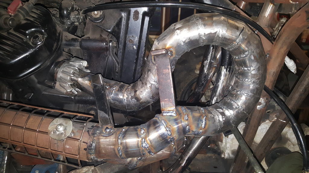
The solution to joing the two bit's of pipe together was this ear trumpet shaped bit of pipe.
It's a tight fit around the transfer box, a very thick ally heat shield will be going between the exhaust and the black electrical gizmo with the word up, upside down.. Don't want to melt it!
Apart from grinding down lot's of welds that's the exhaust system done
Next on the hit list to sort is the shifter for the transfer box..
It needs to go somewhere around here, also the bracket looks really ugly so a new one is being made..
The fun bit is going to be making the rods that connect it to the transfer box, but luck might be on my side as I found an easy route through the frame, above the carbs that will require minimal bends to the rods..
Oh, a scrap pile raid produced all the rods I could need
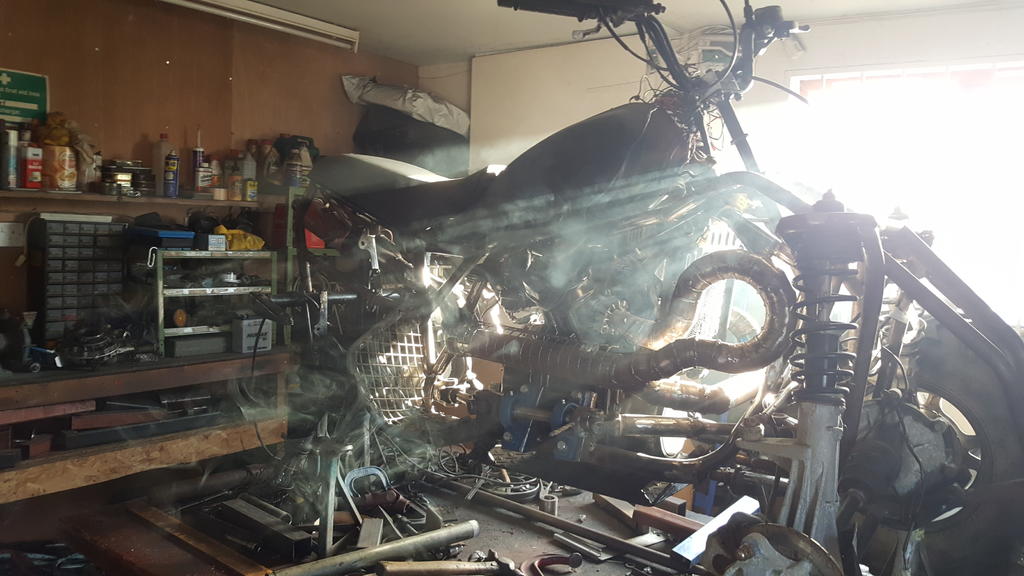
To finish off this update have a moody smokey picture of the MadTrax
Having short stubby pipes sticking out the engine I needed to make them a bit longer and join together.
The first bend, Im going for a more agricultrual look with the exhaust system to make it stand out a bit from the swoops of the frame, so lots of pie cuts going on.
Plenty of penetration which is good to see
The N/S pipe almost done. The long bit that goes across the frame was welded in place first the couple of bits of box were there just to keep it in the right place, below the radiator..
The rest was made up to fill the gap.
Before doing the O/S pipe I needed to know how it was all going to fit into the main pipe which runs along the side of the engine..
Sooooo, how to fit two of the smaller pipe into the bigger one!!
Some measuring and cutting later.. The pipes are over length as I knew I'd need to trim them just not quite sure where yet.
Welded up and slotted in place.
And joined to the N/S pipe..
Before you ask.. Yes the welding rubbish was cleaned from the inside of the pipe sticking out the engine before anything else was welded to it..
There was no way the exhaust system I had built would fit back on with a transfer box and a dive shaft in the way, the only part that fits is the big bore pipe that runs down the side of the engine through the frame!
So a bit of a re-make is needed, I started at the front after slicing off the bits that fit into the engine..
The only tube I have enoug of is a bit bigger than I had been using, so how to go from something small to the bigger blue bit size!
Find a bit of tube that's slightly bigger than the small bit but slightly smaller than the big blue bit and make four long-ish cuts in it.
A hose clip squeezes it down to size.
Welded on and extra tube trimmed off.
Welds cleaned back.
A bit of hammer work soon had the other end a bit wider.
Welded on to the big bore pipe.
Lot's of careful welding later had the gaps filled up.
Test fitted to the engine, one side cleaned up.
Now I have these made I can work out how the next part of the system.... But that's something for Friday..
Oh... the slight change of plan...
With the UJ's etc removed I found there is just enough space to fit this er... final drive? 90'd drive thingy from the very same Honda Silverwing that gave it's engine up for Why Not all those years ago!
I will need to fit a chain n sprocket to get the power from the bike gearbox into the 90'd drive thingy which has a 5 to 1 ratio (I can "gear" that ratio out), and yes it will spin the right way
And to finish off a couple of photos of the unit I had taken to put it on Fleabay.. Quite glad I didn't get around to listing it
Here's the jig thingy I make to keep the shafts parallel. It doesn't lok that much but both the tubes are a nice snuff fit on the shafts they have to fit on.
A lot of time was spent making sure both tubes are parallel to each other.. Trim, measure, trim, measure, trim, measure.. Weld measure, weld a bit more, measure.. You get the picture.
Fitted.. The shafts are now parallel to each so I can start working out how to mount the bearing plate.
Out of interest I put the foot rest/guard thingy on to check it still fitted... Not bad, I will only have to loose a small amount of foot space to fit a sprocket with guard of course.
It was roughly at this point that a couple of comments left on Farcebook had me thinking about how safe the right turn UJ set-up actually would be.. Tight UJ angles and high spinning speeds are not the best mix!
Somehow I don't think I'd be wanting to do a strip down.
You or MadTrax Norm?
And onwards with the story, another slight change of plan coming up shortly..
The outter bearing needs something strong to bolt on to, so I dug out a bit of 8mm plate and set to on the lathe.
It will fit somewhere here, to make life more interesting the plate needs to be removable or I won't be able to get the transfer box back out the frame!
Before I started on the mountings I thought it would be wise to tidy up this bit of frame first.
Mostly chopped out..
That looks better.
Plate and bearing set back in the frame a tad, it fit's rather well..
Plenty of UJ clearance by the transfer box.
Before I can start mounting the plate I need to make sure both shafts are parallel to each other..
Now the fun part, getting drive from the Honda bike gearbox which points towards the back, out the left side of the frame.
A thank you to Nigel at this point for getting a shaft, pulley and UJ off the remains of a Kubota flail mower before it went off for scrap... It really was that rotten!
The UJ in question, heavy duty and with no play in the bearings at all
One side of the UJ is easy to attach as I have the shaft and roll pin that came out of it..
The other end has or (should I say had) some rather large splines!
I'd be lost without a lathe, taking the OD down to size before cutting it off.
Boring the ID out, a couple of arty flying cooling fluid shots
The finished sleeve, yes it was turned down from a lump of steel the same shape and size it's standing on!
UJ, shaft and sleeve..
A nice tight fit.. The sleeve has now been welded into the end of the UJ, yet another roll pin will hold it all together.
Starting at the back, or is it the front!... Er.. Back of engine we have a UJ with splines in one end to slide over the output shaft on the bike gearbox.
A shaft then goes through another bearing and into the Kubota UJ..
And comes out through the left side of the frame and another bearing.
A chain and a couple of sprockets will give me drive into the transfer box
As you can see I have some metalwork to do to hold everything in the right place.. Space is tight but shafts and UJ's turn as the should without hitting anything or feeling "notchy" which proves the concept of it will all work
With all the front drive train bolted back on the foot rest thingy needed a little trim to clear a UJ.. I will add a cover over the shafts/UJ's to add some leg protection should something go bang and start flapping about the place.
Before I started to cut any more metal out I put some strength back in with a nice bit of curved tube that clears the UJ
When the frame is stripped back down I will add some extra metal to tie the tubes together neatly.
This join between old and new tubes just had to go!
Hhmmm, nice rust inside one of the few remaining bits of the original FourTrax frame... It felt good to remove it
There is no neat way of joining big and little tube together, at least the other end is easy
For extra strength a length of steel bar has been added inside, you can just about see it where the tubes join.. The steel bar does go all the way up and in the larger tube.
I like getting good value for money, think I might of got the maximum use out of this cutting disc
Compair it to a new disc!! While on the subject, some cheap cutting discs are better than others, I can't remember the make (Germany is mentioned on the Fleabay ad) but they are by far the fastest wearing most easily broken disc's I have ever bought!
Great workmanship and thought going into this project Ian, grand job.
I hate to say this but, in the photo of your driveshaft, it looks like the shaft yokes are out of phase.
All shafts I've had dealings with, (apart from steering shafts installed at high angles, which don't spin at high speed), always have the shaft inner yokes in line to aid in cancelling out vibrations, not a problem if the whole assembly runs in a dead straight line, but when angles are involved?
Not a criticism , just an observation . You don't want that coming adrift at any speed close to your leg The ideal perhaps, would be a pair of CV joints, if there's room.
Well spotted Doug, I had an idea that the yokes both should be in a certain position but wasn't sure which.. Guess I should of googled it first! At least I had a 50/50 chance of getting it right
The shaft also had a slight length problem as something had moved during welding, so in the vice the shaft went to have a weld cut down.
Welded back up at the right length with the UJ's in phase
The shaft out the TB is way too hard to drill, so the UJ is held on with a couple of grub screws.. I will add a couple more for peace of mind..
The UJ's that fit on the shaft with bearings are a very tight fit on the shaft, so I drilled them out to fit some nice tight roll pins.. The bolts are only there at the mo to make it easier to take things apart (many times) during building and will be replaced with roll pins.
One of the UJ's being a MAN steering coloum UJ is normally held onto a shaft with a nut and bolt one side..
Fine if it's being used for steering but as it will be turning a lot faster it would of been out of balance!
My solution was to cut most of the clamping bit off but leave enough to get a bolt through and clamp it tightly.
(The drill bit is only there to line the holes up for putting a roll pin through)
Part welded up.. A little at a time as I didn't want to fry the UJ.
The bolt head and tread were cut off before more welding, then some shaping.. Still a little more to take off..
Oh, and I found a rather nice if rusty steel bar buried in the workshop, I guess I will be re-making the TB input shaft sleeve, but this time out of one piece..
It's a good job I have just got some more cutting tips and cooling fluid for the lathe
If you're going to use those steering shafts for drive shafts, how about balance? Those clamping thingy's look a bit offset.
HI Doug, I've had another thought on the clamp thingys.. Rather than take metal off of one side to balance the UJ's, it would be better and stronger to add metal to one side and build it up with weld (making sure not to let things get too hot) until both sides match..
While waiting for the bearings to turn up, I thought I'd make a start on a sleeve to fit over the input shaft on the TB..
Not the best photo (I will get a better one) but here's the shaft in question.
The only bit of steel bar I have which is long enough is made from very hard steel and looks like it has been used to hold a JCB bucket on... That sort of hardness!
Anyway, I can make it in two parts and weld them together which would make it easier turning the tapered part half way down the shaft inside..
These two lumps I made years ago as pivot points for a dozer blade that was going to go on the 6x6..
A lot of turning to get them down to size!
At least one is mostly done
Woo Hoo... The bearings arrived
Here's the TB to front end bearing mocked in place..
Best start getting the bearings mounted then.. First up something to bolt them to.. Well, a couple of somethings..
Bolted on. The black bit of steel across the lower bearing bolts is just to keep the bearing square to each other.
You can just see where I welded on some tempoary bracing to the drive shaft to stop anything moving about withough the axle stand and other bits that were holding the bearings etc in place.
If you flip the bearings over you can see the captive nuts that have been welded on... Don't think they are going anywhere
Now the fun bit.. Making four somethings to bridge the gap between the back of the bearings and the chassis/frame..
Starting with a bit of CAD (cardboard aided design) work..
Which goes somewhere here.. Rather hard to hold it in place and take a farto at the same time!
Roughly cut out of steel..
That looks better.
Four of em made and tacked in place..
Bearings off..
Fully welded up... Almost.. It will be easier to weld the extreme top on bottoms where the brackets fit on the frame without the engine in and sump guard in place, so that can wait until stripdown time.
Welds ground down, a nice curve at the back to clear the engine.
And most importantly, there is still plenty of UJ clearance here..
And here
And to finish off this update, a photo of the bearings etc quickly bolted on for this very photo.. The mounts were still very hot from welding and grinding so I didn't want the bearings sitting getting hot for too long..
To get the drive from the Honda bike gearbox to the TB I had to find a way of turning the drive direction around by 90'd..
One of the steering UJ's fitted with the the splined section from the original CX/trike propshaft..
The shaft will run diagonally between the engine and TB with a nice meaty bearing to hold it in place.
And via this double UJ thingy the drive will come out the side of the frame through another meaty bearing and put the drive in the same orientation as the TB input shaft..
Working out space for the TB to front drive shaft.
Using a mixture of different shafts and UJ's there is plenty of space to run the front drive up the side of the engine.
Hhhmm... Maybe not quite the same size where they need to be joined!
A bit of lathe work later..
Ta-Daa
Not fully fitted together in this photo as I don't know the exact length yet, but you get the idea
Popping back around to the other side of MadTrax for a mo, the pulley (I will be using chain and sprockets) is about the right size to give me an idea how much space I need to create to fit a bearing in.
I need to slice some of the frame out here, but I planned to do that anyway to get rid of the un-needed swing arm mount.. It's the only bit left that says "I've welded a few extra tubes to a bike frame"
The bearings arrived Wednesday but I've not had a chance to do anything with them.. That's fun for tomorrow
If you're going to use those steering shafts for drive shafts, how about balance? Those clamping thingy's look a bit offset.
Well spotted
The off-set bits of the UJ's will be ground down to make them..er... Not off-set
As I will be grinding off the bits where the clamping bolts go I will need another way of making sure the UJ's don't come off the shafts..
On the Quadzilla roll pins were used, so that would be the way to go I think..
The TB didn't officially have a mount around the input shaft I thought it might be wise to make one as a lot of forces will be going into the TB there..
A cardboard template taking shape, pencils being just the right size to screww into an M8 thread
As I didn't have a big enough bit of strong plate to make the bracket from I had to make it in two parts.
Two of the bolt holes on the TB didn't stick out as much as the other two, so to level things up a couple of spacers were added to the inside of the plate.
Welds cleaned up. The chain driller hole is slowly getting filed round. By doing it a bit at a time it breaks the bordom/arm ache up into managable bite sized chunks
Bolted back on with a few extras.
The top right hand bolt bolts into a threaded tube thats welded to the strut tower.
As any "tabs with captive nuts" type things would get in the way of reoving the TB, I had to come up with another mounting spot.
Something like this..
It was also a good time to mark out a bolt hole.
Off with the bracket them slice the top off the foot rest mount..
Drill it, weld a captive nut inside then weld it all back onto the frame... Top mounting point sorted


")


")


more scrap
in Pedestrian Operated Machines
Posted
Love the truck, collections and deliverys in style