| |
-
Wow!, That all reminds me of 17th Oct 1987 at this end of the country. Hope you get straight soon with the damage repairs.
-
Long time since I posted. Norm, yes. Although since i said that, my chances of actually making them is diminishing. The wrist joints are a real issue now and holding up my progress on many things.
Prioritising this project has now brought it to nearly finished stage. Last week, it took 2 days to mask off the rear wheel sides and strakes (treads) to etch prime/paint the faces of the rims-
Need to dull off the front rims next
With this back together on wheels, I finished making the alternative drawbar for the Water Cart so it can be 'hitched up'.
Trial fit to check levels-
Hoses and plumbing to do on this next.
Regards
-
Thought I'd just add an update, as it has been a while and only recently able to progress with this one.
It does not really fit in this forum section as a project. So just to say that I've got it nearly all back together.
When it is properly running, I'll add it to the 'Other Garden Machines' section
-
Hi Norm, Sorry, I did not intend to make it look like an advertisment for a sale on here. I'll drop you a message when I get sorted.
-
Nice job there! . .......I'll know who to ask about the JAP 2a if I have any probs with the one attached to a pile of rust that I've been asked to breathe mechanical life into.
-
Nice project/machine. Always wanted to get my hands on a Blackburne. Shaft driven magneto br looks of it?. I presume you have all the info you need by now?. Do you know the Mower's age yet?.
-
Hi Norm,
Not a good experience when it happens. Those forks are the 'Achillies Heel' of the WH trans, considering the rest of it is built like a Victorian brick WC.
At least the parts fit back together with a register for lining up again. Look's like there is a bit of wear around curved fork face as well
Hope the weld job works ok to save money and get it fixed.
I have the surplus C-120 8 speed trans sitting around and wondering if I could be bothered to put it on the Job List and open it up for an overhaul?.
Too much on the go, so may just sell it on with my stock of new roller bearings etc, just to make space.
-
Hi All,
I've been advised that Paul at Meetens (UK) is planning to cease trading for health reasons. Don't expect to receive an immediate response for new orders etc.
I, or someone hopefully will update this with any further news.
Also, those who are into Mower/Engine parts etc, I believe Jon Cruse of Hailsham is struggling with health issues and may have to cease trading, but need to confirm this.
Regards
-
.........If anything.........That was the issue I was asked to sort out recently. A heavy bronze carb fitted to a small water cooled 1/2hp engine from 1923 and had been adapted to fit onto an early 1930s Lawnmower!!.-
I actually found a Manual and parts list for the engine, but of course not one single available spare part. Failed to find anyone else online familiar with, or who had a similar ''N' type engine made by Stuart Turner.
Several bits missing according to the parts list diagram and one item had fortunately been acquired from ebay...the all important Float Bowl (screw on) Lid.
So I had to make and find the bits etc, so as it had not run for god knows how long, it was dismantled-
Certainly overdue for a clean and repair. The small clip under the spring (bottom middle of above pic) should be fixed by solder to the float. It holds the needle at correct height.........duly fixed.
Established that the large hollow brass nut (top left above) which acts as a sediment bowl should have a screened filter and a spring within. items (on left of next image) 4044/4045-
The bits had to fit within these parts-
So after a search for materials, a bit of lathe time and some soldering, I had the 'makins' of the necessaries-
The 'Stove Pipe' top hat filter body was silver soldered together, so that I could soft solder the mesh to the bottom and sides. But not before it was subjected to some careful milling to put some 1/4"wide slots into the side wall.
Appears to be some distortion in the image below which makes the filter body look crooked, but assure it is not.
-
I was lucky to find in my stock, a suitable spring to apply pressure to the filter and keep it all in contact with it's seat. That filter/sediment body nut is 1 inch A/F.
So all done and ready to bolt on. Now super clean inside and favoured the patina to polish on a motor of this age-
Oh and yes, I have the task of getting this thing running/working, along with another pile of broken rusty bits......I may be some time!.
Regards
-
Good to see you back postin Ian!. Should help to stem the flow of tumbleweed and the sound of howling wind across the forum.
Good work there. A much larger form of 4 way tool post than I have on my old myford, but they're sooo handy.
Keep 'em coming.
Regards
-
Hello Gents,
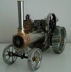
Thanks for viewing and your comments. A little more progress to date. The front end is more or less sorted ready for the chimney to go on and is now sitting on it's front wheels.
The cylinder in the original model design had a bland side face just shaped and usually painted black. I, as may be seen in a previous post, just had to make things more difficult for the sake of detail.
I made up a cover plate and secured it with screws as per the full size engines. This has been painted the same dark blue as other parts and (I think) helps to finish the area off.
I have just replaced the last temporary screw on the cylinder part for a stud/nut, but you will see a countersunk screw in the top Guide Bar in this pic which I had taken earlier.
The tiny (7mm dia) steel handwheel on the Blower Valve was drilled and finish filed by hand/eye, but looks ok I think.-
The steering chain drum finshed and now fitted is also modified from the model design to reflect full size layout. The chain (brass) is what used to be supplied to clockmakers for the winding system on long cases.
I plan too make my own at a later stage in steel with brazed links-
Lastly for now, I finished making the square headed blanking plugs and stop pins in bronze for the water pump and now fitted in it's partially hidden place down behind the rear wheel.
Original model design was for it to fit on the side of the boiler, which looks way out of scale, and over the years, other modellers have experienced priming issues when in steam with boiler mounted pumps.
I think it is because of the heat, but I fortunately redesigned this back in 1987 to locate in a cool area similar to full size layout-
Sorry about the last image quality, I deleted the wrong one . You may notice a red dot adjacent to gear tooth on both the 2nd and 3rd motion shaft gear wheels.
I have a slight resistance in rotation where these two coincide, so i think i must have a tiny burr on them, so i will pull these off and run them with some p600/oil & 'T' cut grinding paste to bed them in.
The running clearances were set using cigarette papers (about 0.0015"), so it doesn't take much to obstruct free movement. Hopefully more soon.
Regards.
-
After 2 months of poor weather conditions, I have managed to continue with painting and some assembly. I finally fitted the last of the valve covers on the cylinder block after setting all the valve event adjustments and finishing the motion work off to a standard of sewing machine smoothness. This allowed me to apply a penultimate semi matt black coat over all the joints, stud heads and nuts to consolidate the whole finish. The Chimney saddle and the exhaust pipe were painted separately, as the saddle is bolted, instead of the original model design of riveting. It is easier this way, as I can reach into awkward corners and touch in the bolt heads with the Airbrush on a fine setting.
Just need a little more care this way of fitting without paint damage. I detailed the exhaust a bit more with fitting a bolted flange at the cylinder end. The exhaust is 1/4" diameter pipe for clarity-
The Regulator Rod just under the safety valves in the next pic has a dummy tail rod and gland. I have to make the 2 x 14ba studs and nuts for it yet.
I decided to machine and file it from the excess metal on the casting to give it some detail, as the original model design just showed a lump of round metal there.
A bit of cleaning up of the overspray on the raised brass lettering to do, but otherwise a major step forward on the assembly front-
I did manage to get the top coat on the flywheel last month and very pleased with the finish. Only temporarily fitted, so the gib key pulls out easily-
Hopefully progress and updates will continue to speed up now, as the jobs on other projects are building up as well as work down at the museum.
I have managed to get some lathe time in though, helping out with making unobtainable parts for old mowers for a guy on the Old Lawnmower Club forum, so I have been busy really.
Regards.
-
Very nice project you have there. Good machines. The top cylinder condition is very familiar to me from past experiences (and current ones). Certainly better condition than the sort I get.
Keep to updates coming .
-
Sorry for the resurrection of this one, but thought those who watch Gardener's World (BBC uk) may see this mower (briefly) on this Friday's programme
It's included in Clive Gravett's (of the Budding Foundation Museum of Gardening) 2nd instalment on the programme covering the history of the mower.
It is also in the Atco Centenary Video on their website:- LINK within the 1950s period. So at least it's still earning it's keep with the Charity.
Regards.
Richard
-
Hi Norm/All,
Well I made the pins from a larger size. I had to reduce them and 'draw down' the eye part to under 1/16"dia, which is still out of scale, but much closer and still manageable to fit/remove.
Well over the last few days, I've made a bit of progress with painting and assembly.
Got past the difficult bit of fitting the horn plates, shafts and the Backhead fittings with minimal need for paint touch ups. Bit difficult to get enough light into the dark areas of black painted bits-
The fitting of the Tender to the horn plates went ok and has 8 x 8ba bolts/nuts on each side, plus 4 x 7ba for the axle bearings.
Original design was just the 4 bearing bolts and a single bolt/nut at the top each side.
Quite pleased with the colour and should look plain, but smart when finished.
I even made the steps with a 'raised' pattern chequer plate, rather than just saw cuts. The bright handle fitting serves to bolt the coal bunker plate to the tender side -
The oil boxes all have filter screens inside to keep the moving bits clean.
I think I will dull off the duck boarding a bit, as it looks a bit 'orange boxy' yellow to me.
Regards.
-
18 years eh!, I bet it doesn't seem that long. In fact I bet it felt like last week when you posted this-
Only 15 years
Glad at least we are all still around to enjoy them.
-
Many thanks guys. Hope all are well and upbeat on the anticipation of getting back to normal. I'll try and make greater progress on this before I post more pics after this post.
Along with other parts, I have managed to get the last top coat on the Tender/Manstand part of the engine which was giving me a challenge trying to keep it free of contaminates while spraying.
Completed the assembly of the front axle with the addition of the 'Spud' ring and pan design to the model-
The 'Pan' part was fabricated with a lid from a Duraglit tin. The design was copied from photos of a full size T Engine.
Fitted the finished wheels that have smaller hub caps and correct style 'Oilers'-
The colour is a dark royal blue over black primer which is close to Prussian blue.
There will be no fancy fairground colours or coach lines, as this is to be representative of a 'bog standard' utility general purpose engine.
While it is mainly still in bits, I take the opportunity of fettling the 'motion' parts to ensure they are all clean, close fitting, but smooth.
The con rod is a redesign to full size spec, which was a bit of a challenge when I made it 30 years ago with little experience of working metal or machines-
The all important Reversing lever and quadrant are also redesigned as per full size versions. For size comparison, the 3 tapered pins in the weigh shaft (bottom) are 3/64" dia (1.2mm)-
The finish on the lifting linkage below is after it has been dulled off with sulphuric acid, which makes the appearance more in scale.
The tiny split pin in view is 1/32" dia (0.8mm). I had to reduce the size a bit and make 10 of them-
I hope to make more progress in a week or two and hopefully start to look like an engine.
Regards.
-
Hi Ray,
Hope all is well. I can offer a suggestion in advance of Wristpin's more experienced answer. The 130902 version has a vertical Pulse-jet carb fitted, so I now understand the orientation of your picture after checking the Workshop Manual.
I suspect the spring has jumped off it's seat of the nylon cam lever which operates the choke.
It needs to be repositioned around the back by the plate and tab in the picture below in the direction denoted by the blue arrow and it needs to pass below/behind the tab by the arrowhead to where there is a recess or lip on the nylon lever for the spring to catch on.
I can now see it in both of your pics and looks to have been disengaged for some time, judging by the debris in the recess-
I may be wrong. but the top of the spring end looks to have been bent upwards (in your first pic). I suspect it should be a 90 degrees and should lay horizontlal.
Regards.
-
A very nice project.No doubt you intend to bring it back to full working order!. With that in mind, and looking at the seat condition in your first Topic back in November, I see it as/or looks like rotten plywood.
If so, scrap it and use the old parts to make a new seat. If you are going to sit on it, you've got to be comfortable, safe and able to control the machine.
There are many ways to 'age' good quality birch faced ply, while keeping it waterproof and strong. This will fit in better if you plan to only clean and 'oily rag' it.
If you go to 'back to new' looking, then you can dress the wood with varnish etc. I imagine you could also use solid elm or ash if the panels are not contoured (i.e bentwood).
I certainly would not criticise it if I saw it at a show and it ended up with a newly varnished seat. Enjoy the project.
-
Well, It's a bit quiet here again. so I'll add an update in the hope someone will be along later and may want to view something recently posted. Would be sorry to see this forum close.
Switched my attention over to the Engine where, for longer than I had planned, have been making tiny bits I'd delayed until I began the final assembly.
Loads of preparation before I could dodge the weather conditions and get the etch primer on during the good still, dry days since last September.
Tested the water pump and all's well, so fitted to it's permanent location-
Did some micro milling on the pump's eccentric sheave using a 1/16" diameter Slot Drill to reflect the casting style of the full size.
Finished the motion work at the cylinder end and has all the full size detail design specification incorporated-
The Back Plate carrying the regulator lever and the gear selector now has a number plaque fitted.
8mm between the fixings and the numbers bent to shape with tweezers from tinned fuse wire, sweated into a bed of solder in the recess of the plaque and painted.
The numbers relate to the boiler's certification reference numbers-
I shall be dulling off all the bright polished steel bits using the same process as in the Water Cart wheel rim faces.
The pump eccentric strap and rod (2nd pic) have been treated and look much more realistic in this scale.
I have managed to get some top coat onto the Tender/Manstand and a few other parts today, so I hope I can maintain the progress rate.
Regards.
-
It is possible there may be one in the stock of the Museum I volunteer for. If your project is long term, I'll check it out as soon as the Lockdown ends, or restrictions lifted.
Do you know the year of manufacture?.
I suspect the Carb was a Villiers Lightweight 3/4" bore, but not sure what the jet size would have been. We do have an Oxford Allen Scythe down at the Museum, so I could check for you then.
-
Thanks gents.
Hope all are dodging the virus and keeping sane.
Hi Norm, yeah, long wait , I've decided not to go down that route. To get a decent 1/12th example, it's about a £100.
It will be stand alone with all the fittings options, or attached to the Engine, which would make the shafts redundant and were only really an exercise for me initially.
Not much to show for in over a month what with the cold temps.
Geared up ready the moment the temp gets above 10c and low humidity to carry on painting this and the Engine.
Sorted the issue of dulling off the steel rim faces, well it will do-
9
As I had already painted the wheels, I used a homemade type of 'Q' tip loaded with 37% Sulphuric acid and continually rotated the wheel to keep the applied acid even.
Took 5 mins each wheel, then clean off and neutralised. Did not affect the paint and will get a coat of matt lacquer over the whole wheel(s).
I should really paint the shafts and props the same as the body, but will leave them for now.
Spray bar and connections to finish. Hoses to make next when the materials arrive.
-
I reckon 8?..... 4 assorted Sprinklers, 1x Electric pump. 1x Spade foot. 1xBilhook. 1x Pruning saw. Having a clear out then?
-
Yes, that's correct. I put the 2 sets in using the cleaner ones as the anode and the dirtier ones as the recipient cathode which get cleaned.
It gets most of the crud off before the anode set deteriorates too much and is easier to clean with a wire brush etc.
-
Certainly got some use out of those!. Seems you have a good stock of replacement sacrificial anodes.
I have two sets which I swap over using the process to help clean them off. I suspect your usage rate is way higher than mine nowadays.
|
|