Don't panic, you don't need to take the spring out, it sits in the centre of the starter reel bearing, if it is that part of course.
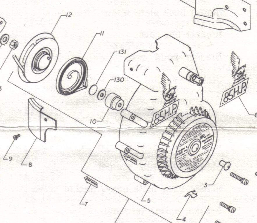
Could it be a non original replacement for part 131?
The carb disc is a very thin piece of pressed aluminium or a loose flat disc on most engines, later ones can have a smaller diameter flat disc glued to the diaphragm.
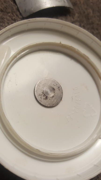
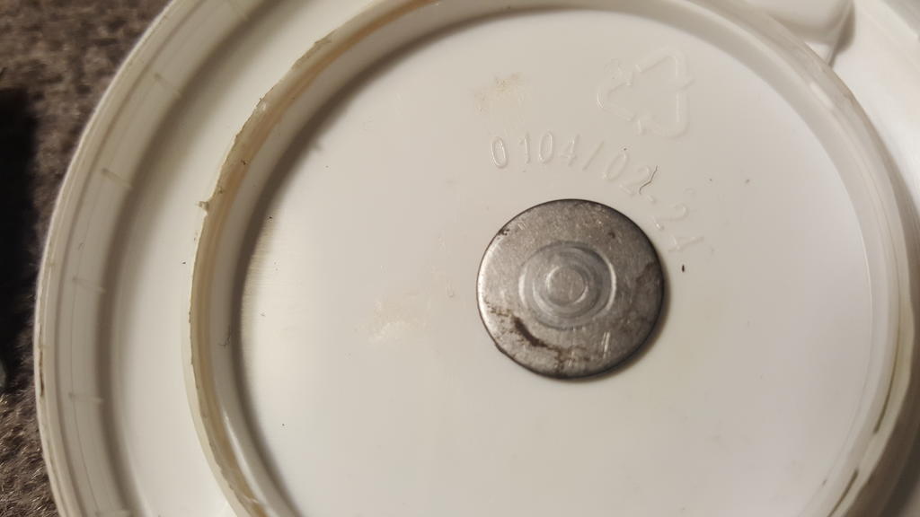
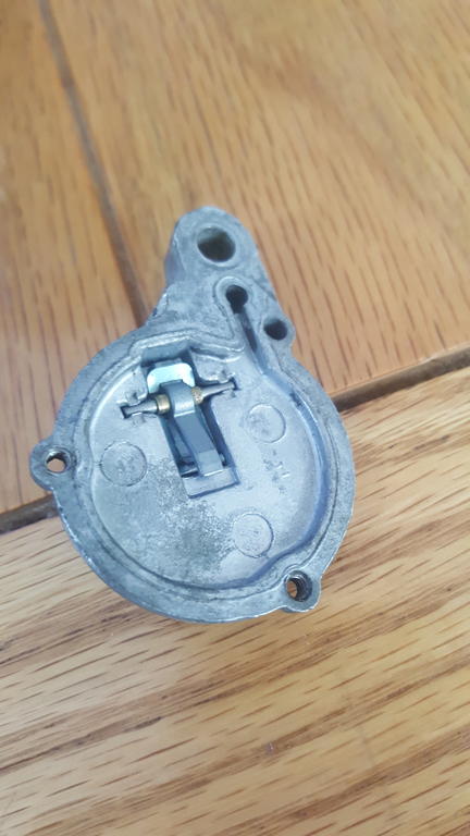
Could we please have a picture of the other side of mystery part.
David
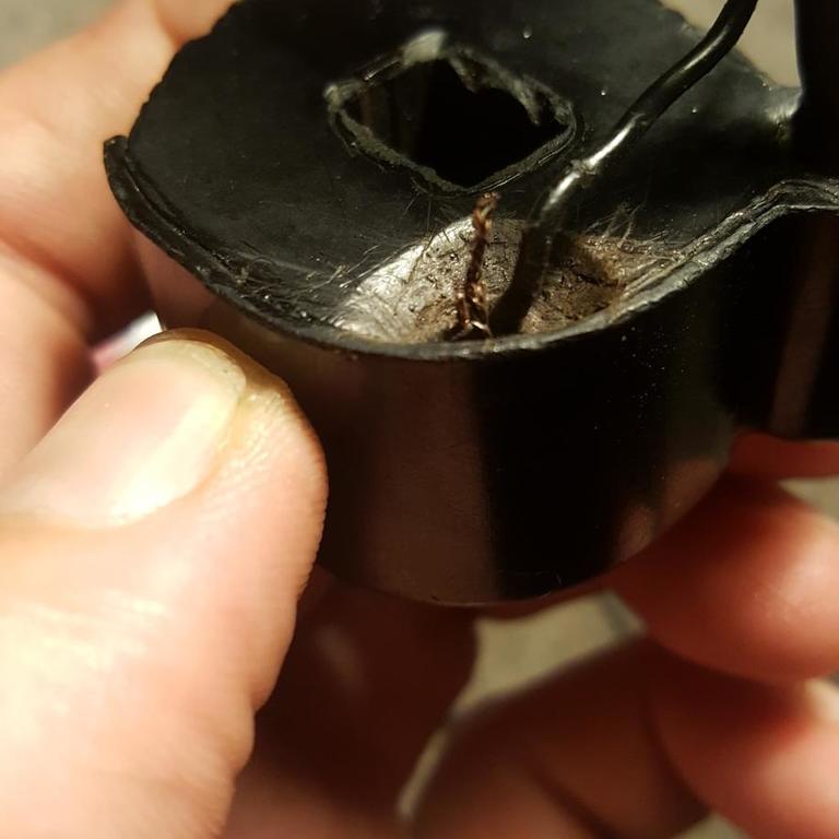
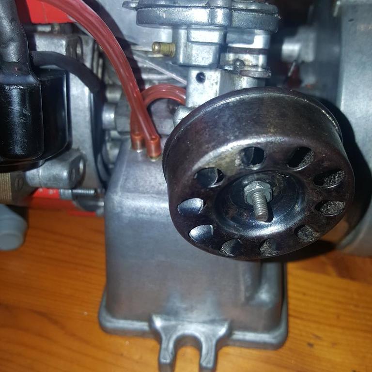
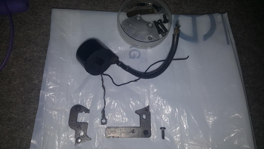
The wear marks on both sides correspond with it having sat between oil hole and flywheel bolt.
The other side has markings to match the recoil housing oil hole.
The wear is only superficial for the most part but the pictures give a good idea of what orientation it sat in.
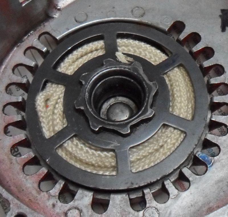
I'm not so sure it's from the carb, I think it maybe from the starter (part 131 on the diagram below), but it depends on the exact measurement & thickness, I can't tell from your picture if it is flat or not either.
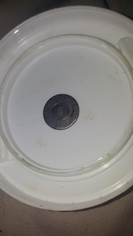
Here are a couple of pictures of this part (listed as crankshaft thrust disk) which often falls out & is often missing too as a result, I did measure one earlier but have been distracted since & have forgotten, will check it again tomorrow.
David
You're spot on!
That explains the strange wear markings on this too! (Flywheel bolt spinning against it!)
Top detective work there. Glad we sussed that one.
Can replace it now, although, I'm wondering if it's all that necessary? The recoil seems to function perfectly happily and with the spark removed the engine spins up no issues without any apparent issues inside the recoil housing while the flywheel is spinning.
I remember putting the recoil spring back in all too well when I fixed that way back still in the Philippines. Was such a pain to get seated properly. My hands still bear scars from it.
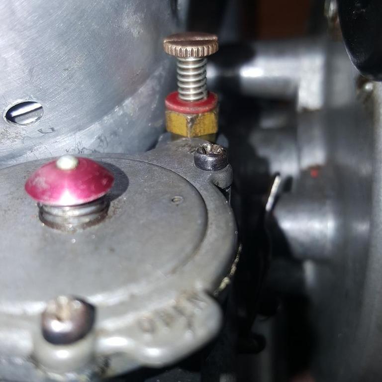
The spring keeps the adjustment screw from moving due to vibration from the engine when running, your replacement looks very similar to the original.
I guess the NGK CM-6 should be OK as it was running with one before, it's about 2mm longer reach (the threaded part) than the Champion UY6 . I did buy a selection of alternates (AC 104, Lodge C10 & KLG TEN50, all NOS) from the Green Spark Plug Company, but they have mostly all sold out now. There is a error with one alternate listed on their website, the Wipac P4 is too long and is 14mm not 10mm.
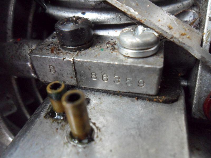
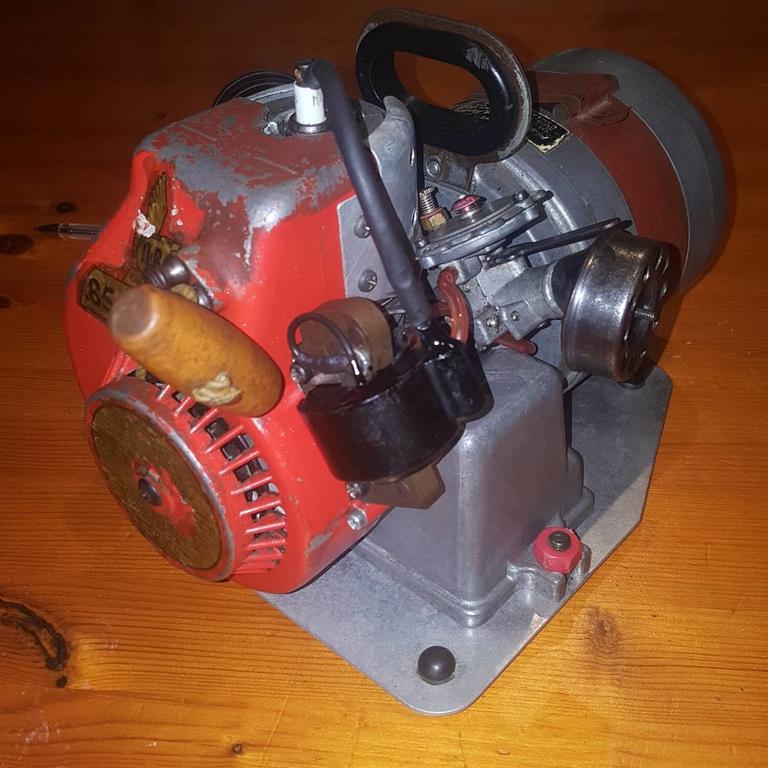
Yes the engine serial number can help with dating, but we can only estimate dating of engines made before June 1967 when they changed the sequential numbering system to a coded number system that gave the year & month of manufacture. I would estimate your engine dates from around 1965. The engine on my Tiny Tor (which started my collection) has a serial number close to yours (086359), old picture below.
There is no information for the paint codes O&R used in any of the original literature I have, I guess they wouldn't help much as you would need to convert them to the equivalent European paint code. Some of the red starter housings on my engines have also faded to an orange/red. Pmackellow on here has repainted some of his O&R's, I think he uses standard rattle cans from Halfords.
The air filter & exhaust muffler were not actually painted, they were finished by bluing, look up "gun bluing" for information on how it was done. Kits are available for bluing steel but I've not tried any yet.
David
Good evening David.
I think you're right, the spring looks very close to the one on yours. I have a further 7 of these if they're every needed by anyone.
Interesting - the very same supplier I used for the NGK. I think maybe I took their last CM6 then, as they didn't have any others on their eBay store. It's certainly 10mm which is good to have confirmed. Almost identical to the one it replaced other than a slightly different washer on the thread.
I had thought around 1965 as this was when the gentleman who owned it mentioned purchasing it, just wondered if there were exact dates but a confirmation of 1965 is suffice.
It's interesting to note that yours too has a different screw for one of the 4 tank mounts. Mine is simply a hex bolt of the same length, I assume due to lack of clearance around the engine for a screwdriver to reach it without completely dismantling all shrouds first.
Is bluing like oil blacking, or are they the same think by a different name? Tempted to give it a try if this is the case as I've done this before.
I had thought the carb disc was bigger? This is only 10mm approx across. Very little compared to the size I'd been assuming the disc is from other pictures/posts?
If so then this is good news - I'm surprised, didn't come from within the carburetor, I remember that much.
It appeared at some point during the rebuild for sure, all parts have been kept in small plastic tubs (a lid of which I used to photograph this piece), is it possible its come from somewhere else?
Hopefully this link doesn't violate any rules with admin? Please remove if I've overlooked something. As mentioned I find the price to be somewhat insane, you can get an entire engine for not far off the same price!
In terms of alternatives, they wouldn't be a bolt-on option and may require modification. I can get some links if you struggle to find anything, most were found on a popular auction site, under a 'small engine ignition coil' search.
Would be interested in following the build if you DO decide on nitro. Keep us posted
You've done a good job repairing the magneto coil wiring, I didn't bother hiding the epoxy resin at work, but would have used one of the old Humbrol model makers paints I have, it seems to be the only paint that hasn't gone bad with decades of storage.
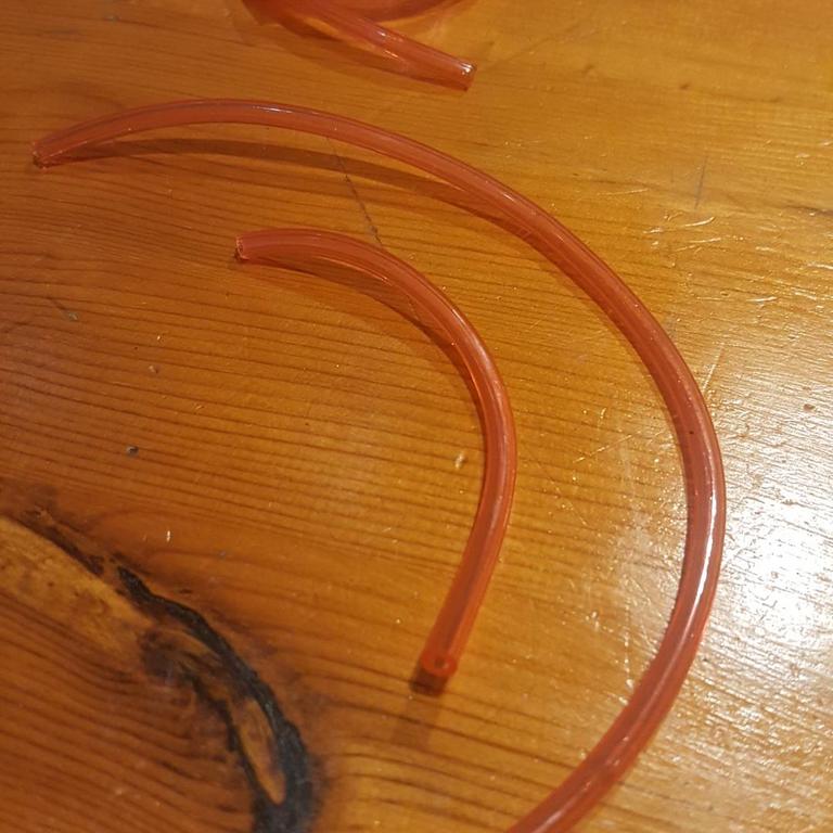
I also found smaller internal diameter fuel line is better, especially as I've not found a source of the thin wall type originally used, it must be available somewhere as I did see some similar (but even smaller) tubing inside a pressure tester from the 90's at work.
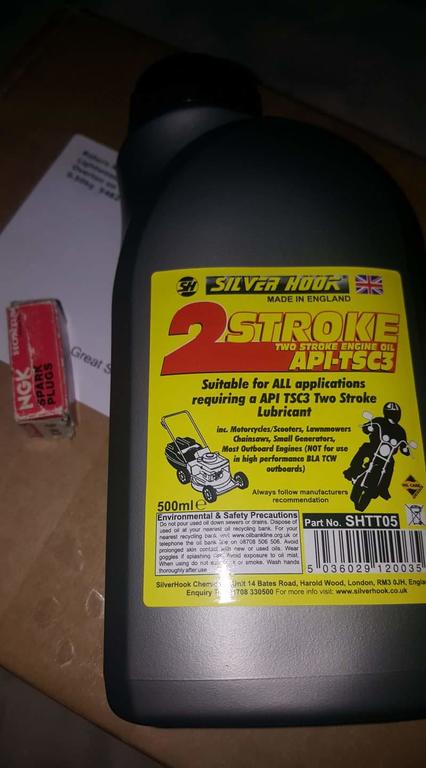
The suggested fuel/oil mix is 32 to 1 with modern two stroke oils.
It's up to you if you decide to repaint the engine starter housing, but I prefer to keep the original paint & decals if possible with my engines.
What is the type of the NGK spark-plug you have used?
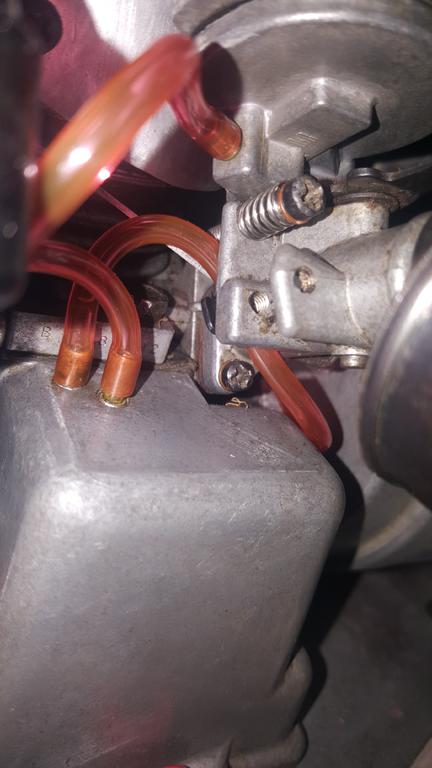
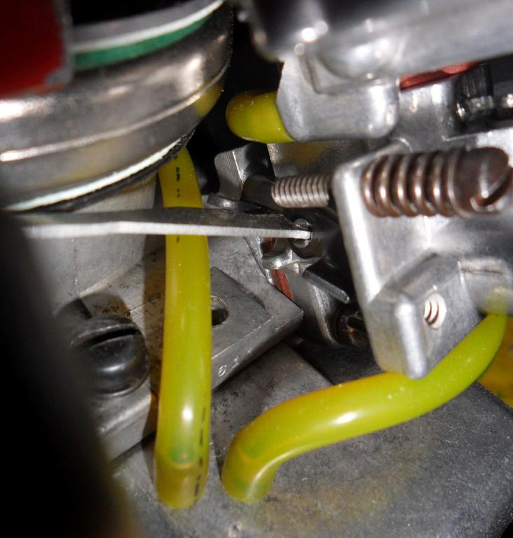
The only thing I've noticed from the pictures in the last post is that you are missing the carb idle screw, it's a #6 screw same as those used on the starter housing but with a thread length of 7/8", it also has a spring as shown in the picture below, it won't stop the engine from running without it though;
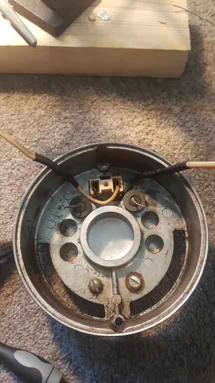
The lower holes are not used on the Tiny Tiger, they are used for the throttle cable on some tools & the Chicken Power bike engine. Your engine does have the letter B for the tank mount model (you asked about this before) it's next to the serial number in the picture below;
David
Hi David.
Good spot, hadn't noticed the idle screw. I most likely have a spare, certainly have a screw but not sure about another spring. Does the tension for the spring matter? Might have a few tougher ones..
I had thought all those holes were for various other applications so I'm glad you noticed that was missing.
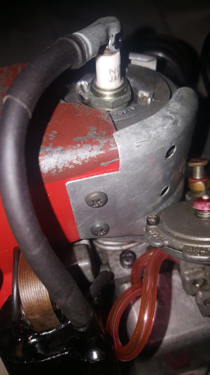
The NGK spark plug is a replacement of the original that came with this particular engine, a CM-6.
They're cheaper than the champion plug alternatives and since it ran with one previously I figured why not. I also prefer the shorter profile of them to the champion plugs.
I've added a spark plug clamp and some more heatshrink today. Happy with the results.
I ordered some gasket paper, since I've done everything else, I figured some proper gaskets in the carb etc, can't exactly hurt. Bonus, paid for A5 sheet, received an A4!
In terms of the engine, yes I remember asking. It's a Type 151B, engine number 086792. Is there anything else that can be gleaned from this aside from what have been mentioned already? Manufacturing date perhaps?
Just awaiting my last shipment from webhead, (diaphragm disk and Mylar check valve) and a test run can be done!
If I did decide on repainting the recoil housing, does anyone have the specific paint codes for O&R Red? I assume for the muffler/air filter housing, black, any high-heat exhaust paint will suffice?
I've done some resistance measurements of the stator windings of two 110V Tiger Tigers & the 230V Tiny Tor I have. The readings confirm the high/low voltage windings are connected together & everything is centre-tapped from the + output terminal.
For the 110V Tiger Tigers the total resistance of all the windings (measured across the 110V outlet) was approx 5.7ohms, measuring from each side of the 110V outlet to the + terminal gave readings of approx 2.7ohms for each half.
For the 230V Tiny Tor the total resistance of all the windings was approx 28.5ohms and the measurement for each half wasn't the same (14.7 & 15.2ohms), I don't have another to check the readings against as I had problems with the 230V output being low last time I tried it. I suspect it has a bad connection somewhere.
I opened the Tiny Tor to measure the low voltage windings as the diodes prevent measurement from the outside, readings for each half were approx 0.3ohms after deducting the test lead resistance.
All the measurements were taken using the lowest resistance range on a quality US made multimeter, which I check against a lab-grade decade resistor box periodically.
I used to have a cheap chinese multimeter which was totally useless for low resistance measurements, you got different readings every time using the lowest ranges as the switch contacts are very poor quality.
Better readings for the low voltage windings could be obtained using a low-ohmmeter as the measurements are at the bottom end of the lowest resistance range on the multimeter. I do have a nice vintage one but it's currently on the round-tuit pile as it doesn't work.
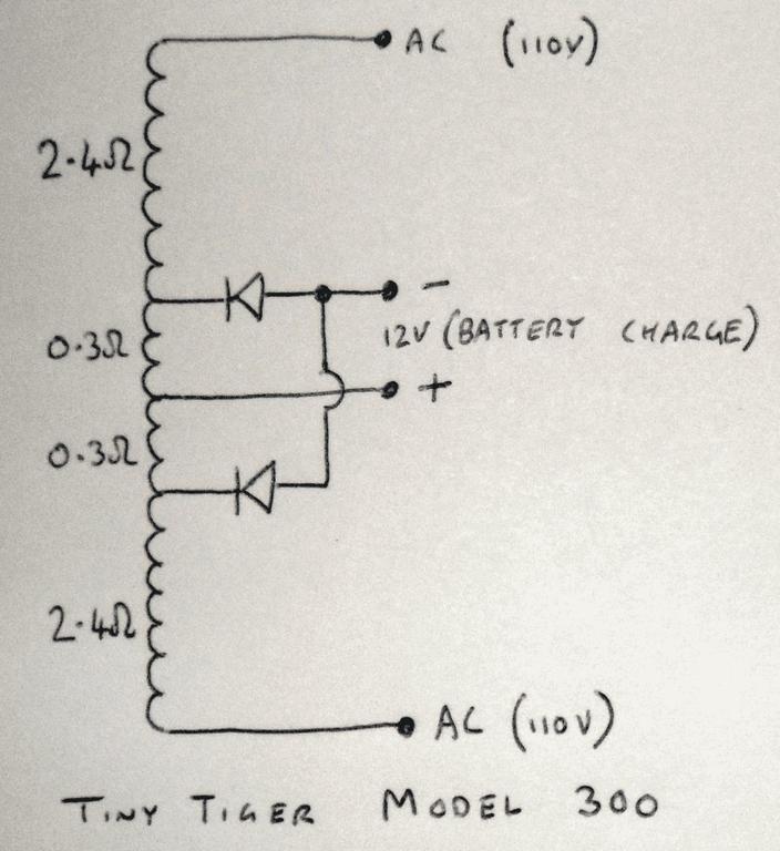
Here is a DaveCAD diagram for the internal wiring of the 110V Tiny Tiger;
There isn't much space for the wiring inside, I soldered the wires to the diodes on the Tiger I repaired as I didn't think there was enough room for connector blocks.
David
Time for an update!
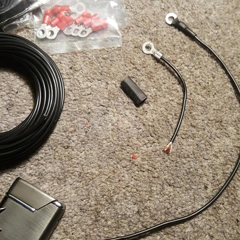
I had to bite the bullet and rewire the ignition coil. I was able to dig enough away as per your suggestion.
I then soldered a new fresh length of wire to them both. The longer one was for the new stop switch wire.
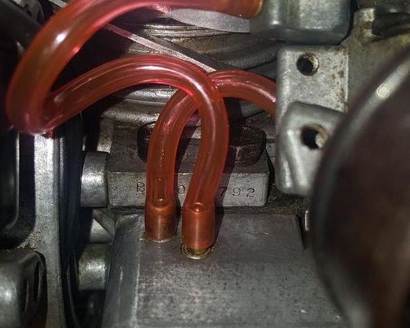
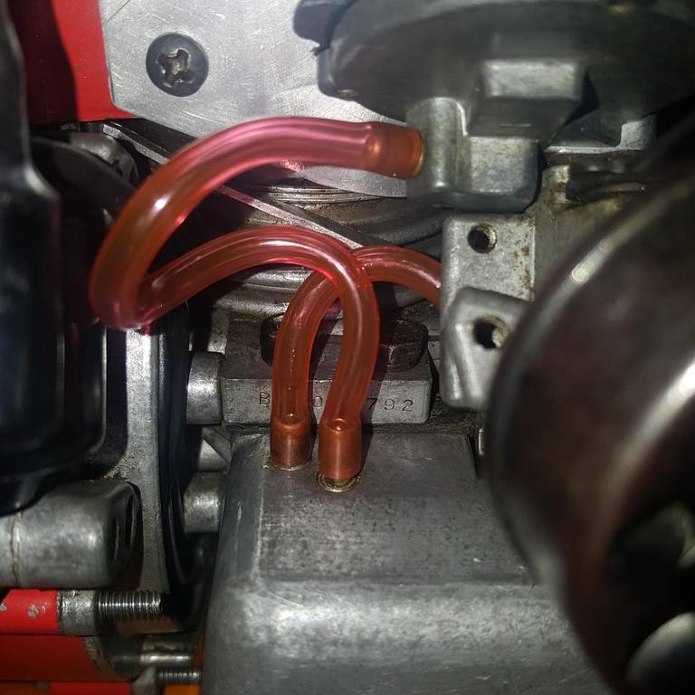
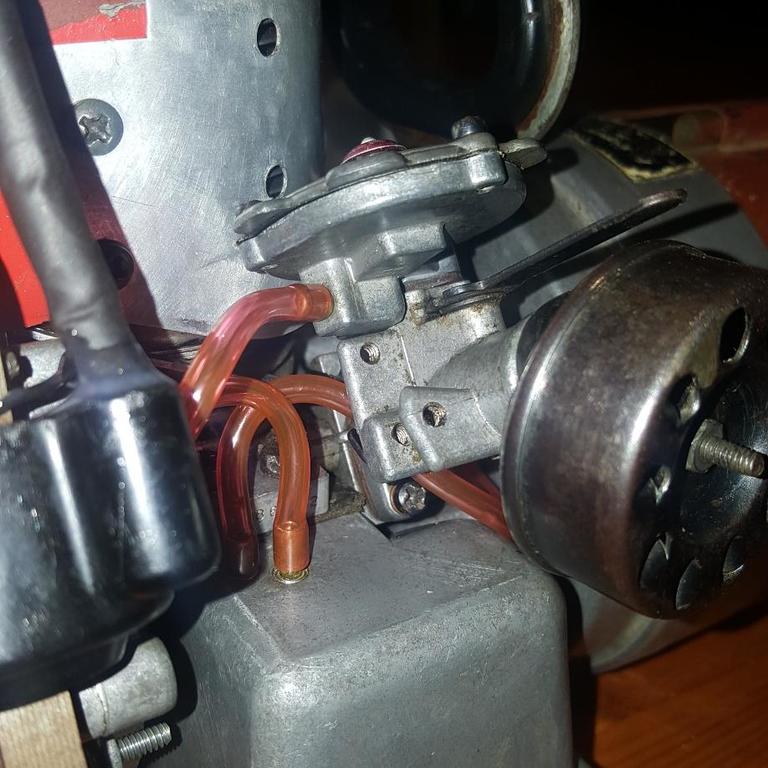
Also got some new fuel line too. 2mm inside diameter in red, this wasn't intentional but suits the engine nicely.
Rather snug on the tank nipples, no need for any clamps!
May need to shorten the carb fuel feed as it's a little wedged in there. We'll see.
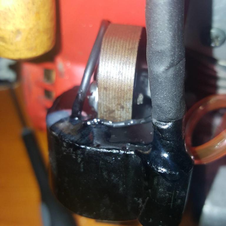
Epoxied the HT lead base and stop switch and armature loop for long term stability.
Really didn't like the way it looked, almost like Vaseline! Managed to sort this out nicely with a 'paintbrush' style black permanent marker.
Also ordered a new spark plug shoe/boot, couldn't get them in singular form, so if anyone needs one, I'll have 3 spare. Shall fit this once it arrives.
In two minds as to whether I should paint it fresh or keep the rustic original look.
I had a spare spring and washer and, it seems functional. We shall see.
Everything is now virtually finished. I'm just waiting on one last part for the carb now.
Few more bits arrived this morning too:
Any thoughts, or last minute things you can think of to check before it comes to running it again for the first time?
Yes if wiring was reversed, the exposed battery charging terminals would have 110V across them, the diodes are probably only rated for low voltage (so could end up short circuited).
David
Quick update with things..
Yesterday I managed to finally clear virtually all the goop from within the petrol tank, the fuel nipple with inline filter unfortunately remains blocked at the moment. On it's third soak of petrol as we speak.
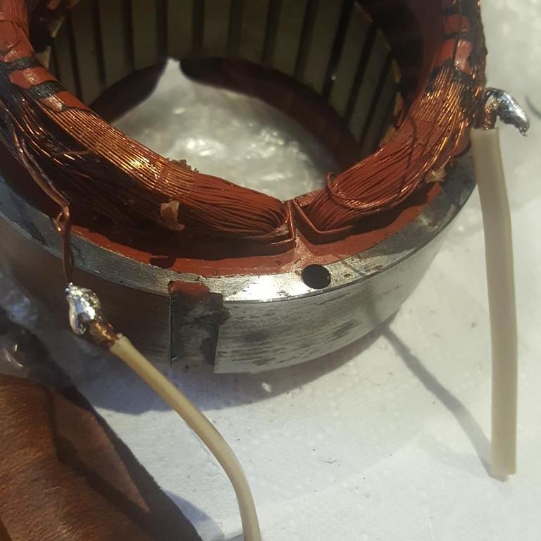
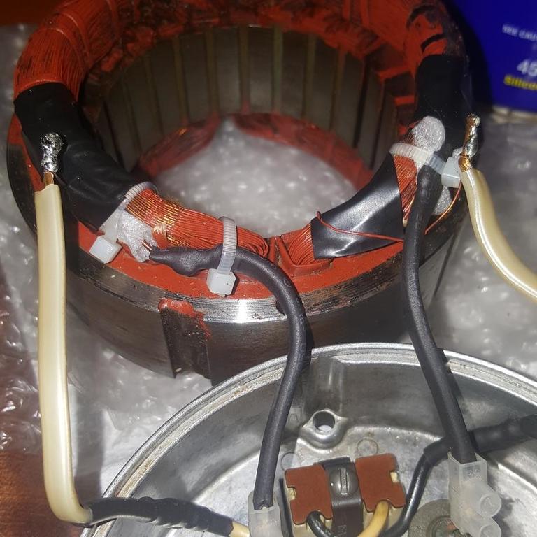
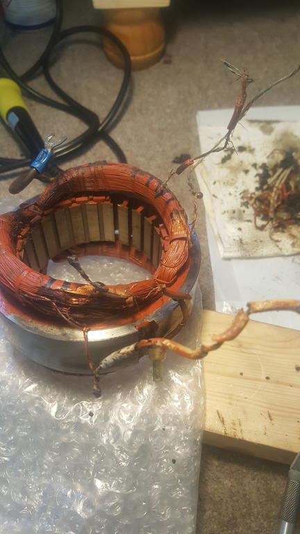
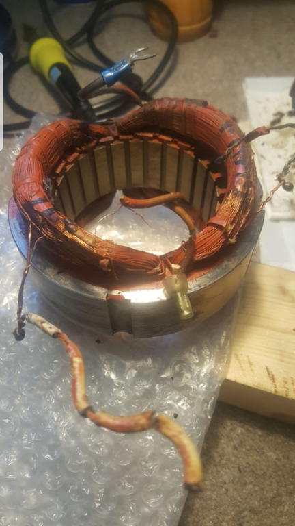
The stator rewiring is now complete as per your guidance regarding high (thin)/ low (thick+thin) orientation etc. Many thanks David!
Pictures are below, it was an incredibly tight fit once putting the two back together. I only hope the soldering is up to the job.
How easily it will go back together, given the difficulty involved in getting it separated, remains to be seen.
More good news, this arrived with many thanks to webhead for his help.
Just waiting on the diaphragm and needle-valve/spring and this should be good to give a test run with a temporary tank, unless it does finally unblock first!
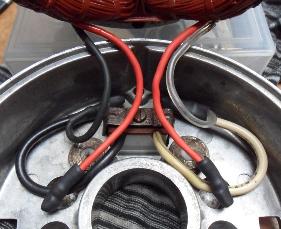
The wiring for the AC 110V outlet has plastic insulation (probably supplied with the bought in 110V outlet) which rarely goes bad in vintage electrical/electronics, rubber insulation on the other hand always seems to eventually turn to either dust or a gooey mess as you've found. We even had a modern rubber cable fail on a 2007ish Weller soldering iron at work, the inner cores crumbled to dust causing a short circuit & blew the fuse.
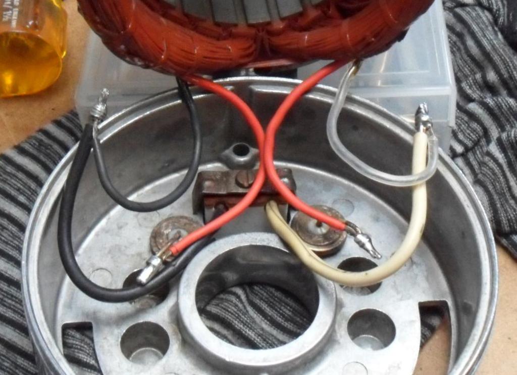
The two items in the casing with solid non-insulated wire leads are push fit diodes for rectifying the AC voltage to DC for the low voltage battery charging output. These will be connected to the thicker windings of the stator to provide the higher current required for charging. The ground lead is the wire on it's own on the other side of the stator.
The AC 110V outlet will be connected to the thinner windings of the stator, be careful not to snap these, you may want to re-secure the cables into the windings with lacing cord as they were before. Thinner cable from a scrap mains lead would have been fine for connecting up these, as the maximum current drawn will be much lower.
As for the the thin wires connected to the thicker winding, I've suspected they were as I got strange resistance readings when measuring mine. I will post a diagram of how I think it's all connected up when I've done some more measurements on mine as I didn't make any notes at the time.
David
Ah brilliant. I'm glad you clarified this for me as that would have been interesting when firing it up for the first time.
Am i correct to assume it would simply have reversed the way outlets functioned if I'd wired it the other way around, making the 12v outlets 110v, and vice versa?
Look forward to seeing the diagram, I can continue to replace/reinstate the wiring for now. I shall use different coloured electrical tape to enable me to identify the lower/higher voltage wiring as I only have black heatshrink and white cable of the appropriate gauge at the moment! 🙈
This is how things stand at the moment:
I will clean and tin the connections ready for soldering to new lengths of cable. In terms of clearance I imagine the space for cabling, once reassembled, is slightly tight so I'll try to keep these as short as I can work with.
Many thanks again David, you've been a tremendous help thus far!
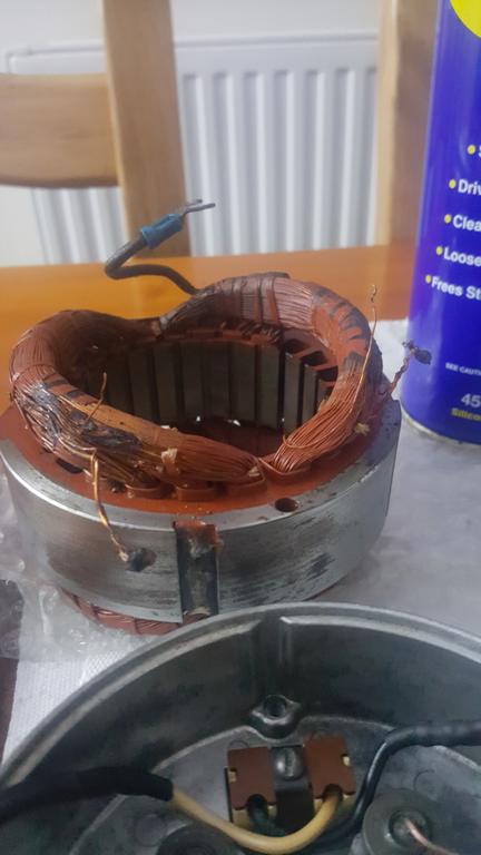
The generator stator windings do look more of a mess than usual, the rubber insulation of the wires always seems to disintegrate when disturbed, did the wires snap from corrosion too?
If you can identify the high & low voltage windings, it should be possible to connect up new wires, if you can find some good condition wiring to connect up to of course. Be careful to not damage the insulation on the stator windings.
You will probably need to clean the wire ends of corrosion for easier soldering, I recommend using a lead alloy based flux cored solder (not that modern unleaded solder rubbish, which requires more heat & has known reliability problems, it corrodes very easily too).
Tin the ends of the wires with solder before joining together and sleeve any joints with heat-shrink tubing to prevent shorts.
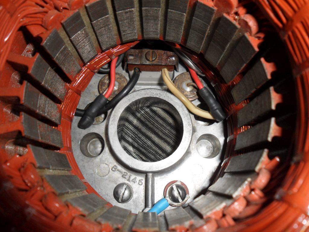
Here are some pictures from the restoration of my Tiny Tiger, it required the crumbling rubber wiring repairing, I took lots of pictures before disconnecting the wires and used different colour heat-shrink sleeving for identifying the low & high voltage windings.
David
David you're an absolute diamond my friend. Pretty sure you read my mind with the pictures as I was going to ask if you had more.
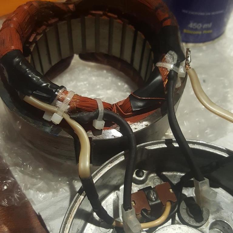
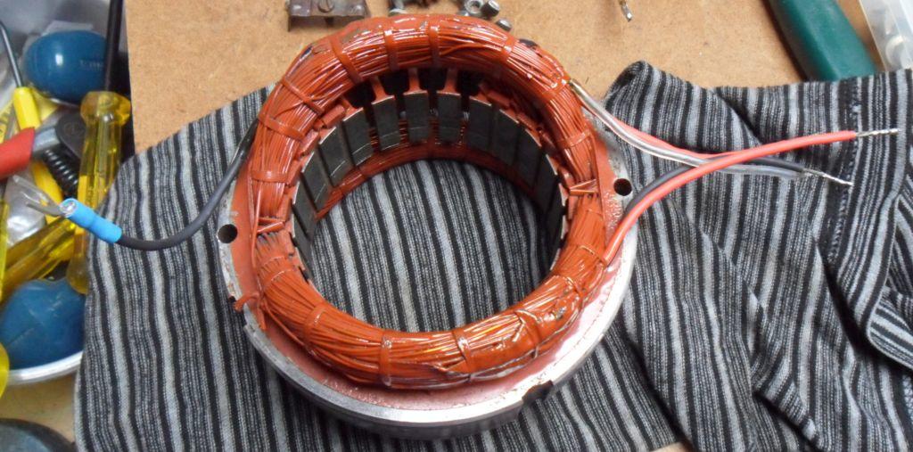
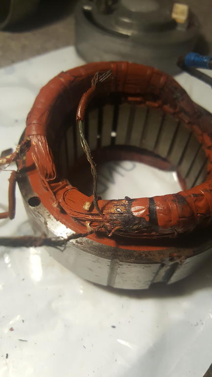
Fairly sure I can rewire from these pictures, I've stripped back all the crud and mess and gotten down to where the wires meet the windings as you'll see below.
Some spare speaker cabling came to the rescue with the rewiring, so far so good. Unfortunately I only have lead-free at the moment but plenty of solder flowed nicely onto the two outputs shown below.
Interestingly enough those two original pieces of wiring survived without corrosion or even the insulation cracking, still fairly supple so I've reused these as the copper was nice and clean after cutting them free of the old crimps.
I'm going to use cable junction blocks to reattach the the two to the nipples inside the casing. Am I right in thinking the lower voltage windings clamp down to these?
On the core itself I have two sets of wiring - both bottom leads connect to a thicker and thin winding, whereas the two upper leads connect to singular thin winding - I'm just hoping to confirm before final rewiring/soldering occurs. See below.
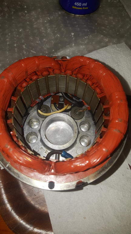
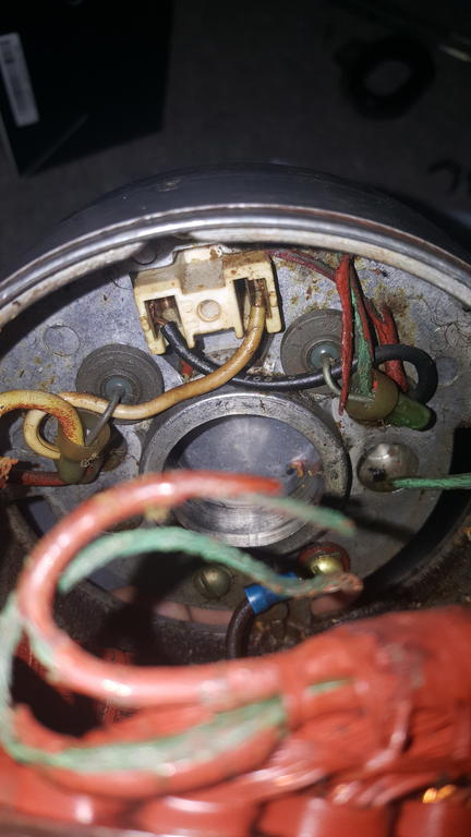
While I await advice regarding the coil (I have an idea - more on that later), I've opened up the generator section to check the wiring - sure enough it's a bit of a mess and heavily corroded.
I am tracing back the wiring to where it meets the motor windings, I assume I can safely replace these lengths with fresh wire - should I find some that's actually corrosion free of course.
The big downside of this coming from the Philippines seems to be the humidity and the wiring! So much for. Any advice will be greatly received.
I've also got some parts on the way, it's taken about 4 days to get from the US to the ParcelFarce depot in Stoke which seems quick, it will probably them another two weeks to move the parcel the last few miles knowing my bad luck with them .
From experience it can take an extra week or two for international shipping between Black Friday and the new year.
David
Good to know. Thanks David.
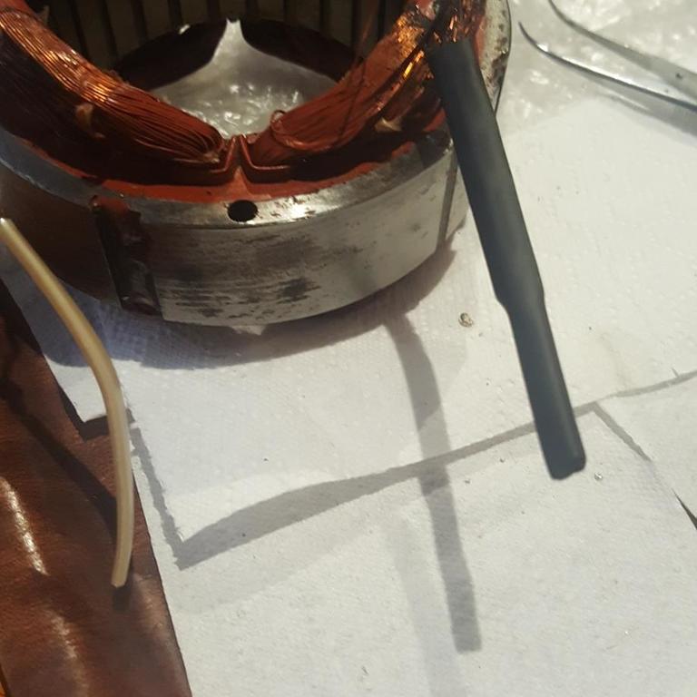
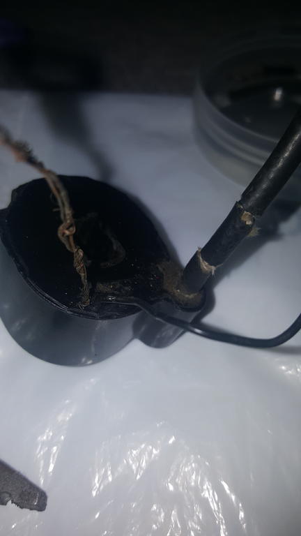
Decided on finally tackling the coil today, I fear I've discovered why there is no spark though! 🙈
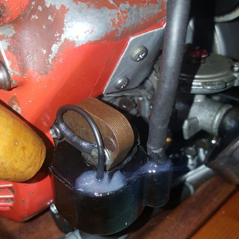
There are 3 smaller wires that come from the coil along with the HT lead that would go to the spark plug.
Two are twisted together (appears to be intentional) and go from a small hole onto the bolt which holds the two parts of the coil frame together, these are not insulated and are visible above - one of the two had snapped off where it enters the coil.
The third is, I believe, for the engine stop and although also broken and lacking insulation in places, feeds to the rear of the spark-gap assembly with the condenser and engine cut off switch.
This one can be soldered onto a replacement wire and should be fine - the other two I'm not so sure about as the break is flush with the exterior of the coil itself and I can't see any easy way to get inside to reattach or replace the broken bits.
Hope the images are clear enough to see what I mean, any ideas on how best to approach this one, gents?
Also - my engine says 'type 151', I wonder if this means anything when compared with others that say 'model b' .. ?
I don't know what sort of Mylar was used, but they are usually re-usable, I found a good used one yesterday, also Wallfish had some new ones made as I mentioned before.
Here are two pictures of the earlier rubber type check valve, I think it's obvious why I now consider this type a "replace on sight" part, sometimes the valve flap is missing or detached.
I've been cutting my own gaskets, but do have some originals, I also bought new O-ring seals for the cylinder in the nearest available metric size, took me two attempts to buy O-rings of the right thickness. See this thread for more on that;
David
Ah I see where it goes now. I wondered where it should be in relation to the other gaskets.
I have some Mylar so I'm tempted to simply recreate one as my old gasket would be a suitable template.
Thanks for link regarding the o-rings David, will look to get some more closer to the end of the build.
Just awaiting the spare bits from webhead at the moment, they'll be coming in two separate packages due to my haste in getting bits and not completely checking the carburetor prior to the diaphragm being shipped to me!
Hoping they'll be here early this coming week - shouldn't take much longer than that I would think.
Yes the check valve is the transparent blue plastic sheet gasket shown on top of the diaphragm in the picture (they were fitted to my Tiny Tiger 400), the originals are usually clear (early ones are made from the same black rubber as the diaphragm), some have probably fallen out un-noticed when previous owners have tried to get them working. Sometimes they seem to be stuck to the thicker gasket (both items are part #6 on the diagram I posted.
David
Does this material have any specific qualities other than being made of Mylar?
If someone has a template of one to scale I could probably cut one by hand with scapels.
David, in regard to exhaust gaskets and their replacement, are these readily available or would they need to be machined to spec?
I found a bottom half of a carb pump that had all of the little parts in it and sent them, including the spring. He did not ask for the mylar check valve, though. He may
still be missing.
You may be right - what came off of/from the carburetor is in the picture I sent previously.
I take it the Mylar check valve is the plastic gasket-like film atop the diaphragm in the image above? If so there isn't one of those here.
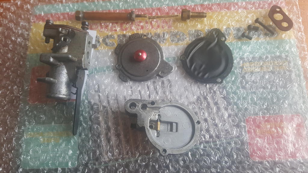
I have finally gotten round to dismantling the engine further - earlier removed the cylinder head and exhaust - very pleased to see such little wear to the internals and crank etc.
Being on a roll, I decided to dismantle the carb in anticipation for the arrival of the new diaphragm from webhead - I've discovered something a little strange. (And that perhaps I should have inspected the carb sooner!)
It appears that the diaphragm is actually in pretty good shape but.. There are a couple of bits missing! (See image below)
-Diaphragm ball valve
-Diaphragm arm
-Diaphragm arm spring
-Diaphragm disk
There isn't a gasket either but I'm told this isn't required and can be reassembled without.
I assume the carburetor won't function correctly without the ball valve, arm, spring and disk - does anyone have these spare that I could purchase them from?
I'm hoping for no more surprises with this engine, nonetheless still enjoying the project.


")


 .
.


O&R 0.85hp (tiny tiger) - Carburetor parts? Coil refurb?
in Ohlsson and Rice
Posted
Could it be the crankshaft thrust disk? Part 148-3. Item 15 here.