
Leaderboard
Popular Content
Showing content with the highest reputation since 06/07/2026 in all areas
-
2 points

Derby Tiller Power Hoe 13B 400
Mike in NC and one other reacted to MrJ451 for a post in a topic
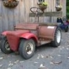
Hi everyone - new member here, and very grateful that I found this forum! I found this Derby Tiller Power Hoe in my father's garage, but when I asked him about it, he didn't even remember having it (he's 84.) Obviously hasn't been used in several decades, and was probably only used a few times. The man has saved every manual, from every piece of equipment he's ever owned whether he still has it or not (ask me about the last 3 lawn mowers he had. Doesn't own one now, but he's still got the manuals for the others.) But this one is no where to be found! I've read through the O&R and AEP manuals in the pinned thread and found some similarities of course, but it's the differences that I need the experts help with. I've removed the air filter - foam was intact (until I removed it.) I have new foam to replace it. The sparkplug has been changed. The cord pulls and retracts smoothly, without catching/sticking. The red button on the carb springs back without issue, but it won't prime - the fuel lines are cracked. (I had a fuel leak into the bucket.) It was stored with fuel in the tank as evidenced by the smell when I opened it. I have not removed the cap that is attached to the fuel line. I would have, but it's stuck and I didn't want to break anything...else. There doesn't seem to be a fuel vent like on many of the other motors. UNLESS that's what the tiny cylinder is that's attached to the fuel line, right before the carb. Obviously I want to replace the fuel lines, but I haven't been able to find dimensions to go with the part numbers (38-11?) The line going from one side of the tank to the other is the one with the leak that I've found. And I have no idea what that little cylinder is - or where to get a replacement if necessary. The numbers stamped on the metal plate of the cylinder cover (2nd to last pic) are 13 - B - 400, 8070907 And there's no On-Off switch, so is that tab circled in yellow in the last pic my Kill-Switch? (Spark Plug Short-out Spring) Any help is greatly appreciated and I can take more photos if necessary! Thank you! -
1 pointThe piece of spring steel arrived yesterday. I will let you know how I make out with it. Thank You..!!
-
1 point
My Wife's Newest Addition (Duster/Fogger)
Mike in NC reacted to Wallfish for a post in a topic
The 20A engine is bigger than the Compact engines are but I'm not sure if the size of the fogger part itself is different. -
1 point
My Wife's Newest Addition (Duster/Fogger)
Mike in NC reacted to Wallfish for a post in a topic
Very Nice Find ! Not very many of those pop up for sale I have one with a 20A engine but not one of those smaller ones. -
1 point
Derby Tiller Power Hoe 13B 400
Mike in NC reacted to Wallfish for a post in a topic
It's a check valve. Make sure you can blow through it in one direction (Flow direction). It may be clogged up from old 2 stroke oil. If it's clogged you can leave it off -
1 point
Derby Tiller Power Hoe 13B 400
Mike in NC reacted to MrJ451 for a post in a topic
Here's the photo @Wallfish Spark works fine. When I started cleaning the tank, paint flaked off, so I'm removing the rest and it'll get a new pain job. Found replacement fuel lines, and I'm adding a fuel filter for good measure. I'm leaving that small cylinder before the carburetor attached since I'm not sure what it is. I'll post pics when I'm finished. -
1 pointAlso, just picked up this “Ranger”. I can’t find much info on this one. Any ideas on the manufacturer?
-
1 pointHere’s a couple of pics from when I got it. In a few pieces now. Getting things cleaned up.
-
1 point
Derby Tiller Power Hoe 13B 400
Mike in NC reacted to Wallfish for a post in a topic
That thing looks to be a great condition. The diaphragm in the carb will need to be changed. When they get stiff it won't prime or pump fuel. And clean the carb. You can follow the pinned carb tutorial. Shoot me a PM for a diaphragm. Check for spark. If no spark you will need to remove the flywheel then the points cover to clean the contacts on the points. Obviously clean the tank too Yes that's the engine shut down -
1 point

Little Petro mini bike
Mike in NC reacted to Tom C for a post in a topic
Thanks, yes this is starting to add up. I believe the first digit in the engine number is the year made? so the P5 1959, 1960, and 1961. then the P7 starts in 1962 first with the early fine finned fan starter cover same as P5 screwed from the back. then the P7 about ‘66-67 with the course or heavier finned starter cover screwed from the front. then later P7 about 1970 with the screw on pull start assembly. then 1975 they went to the T23 engines. then about 1980 they came back to the S22 engines.these look more similar to the Old P7’s -
1 point
O&R Powered Halicki Skate Board 1960's (aka Toby Cart)
Mike in NC reacted to BabaBooey for a post in a topic
Hi All, This is my 1st post as I am new to this forum & hope the knowledge within will provide answers to my ?'s. A friend who grew up in California recently gave me this Toby Cart he used as a kid. It was produced by the Halicki company in Gardena California, sometime in the 60's. The motor is an Ohlsson & Rice, J II .85, the carb, & gas tank are missing so I am on the hunt for both. I have gone thru the motor & all is good to go! This is meant as a display piece so there is no panic or urgency to grab parts. You won't catch me or anyone I care for trying it out! Would the carb be the same as the J I & J III? if so what source if any? where could I get a steel tank? There is not much info available about "Toby Cart" on the internet period. This is what I've researched so far & hope I have it correct. Toby Halicki moved to California when he was 15 & started pumping gas, within 2 years he owned his own body shop & eventually ended up with his own wrecking yard, he started building hot rods & custom cars, fixing wrecks etc, he took real estate classes & ended up buying commercial properties, later he was tapped to do stunt driving in movies & eventually caught the acting bug. He took acting class & ending up writing a script (1974) to a movie titled "Gone in 60 Seconds". The movie was not that successful in N America but Europe loved it & he made millions. Unfortunately Toby died while filming Gone in 60 #2 (1989) on location in Buffalo, a stunt went wrong & he was hurt by a downed telephone pole. An avid collector, Toby also owned one of the worlds largest toy & automobile collections. Thanks for looking & feel free to correct or add info. Sincerely, Don M Ont Canada