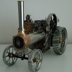
Anglo Traction 1,023 #1 Posted October 20 Just thought I'd share this project with you. I've been asked by the Museum Curator where I do volunteer work, to evaluate and recommission this for full working display and demonstration work. I/we have already started on it, and will take some time. The Atco Mower is a post war 17" model, and the steam power unit and boiler were designed and built in early 1994. In the meantime , here are a few images of it- The challenge I have is that it does not comply with current regulations, so I will have to make changes to the drive and boiler fittings. I'll also add some background to it's story, and who built it. Regards. 1 nigel reacted to this Share this post Link to post Share on other sites
Anglo Traction 1,023 #2 Posted 22 hours ago The first thing we had to prioritise was the inspection of the Boiler to ensure it's design and the materials used are up to specification. We commissioned a specialist to carry out an initial NDT (non destructive test) to establish the material used, it's condition (corrosion) and the soundness of all the welded joints. The process uses Ultrasonics. All results came back positive- This gave us the evidence of condition to move to the next part of the process. Fortunately, we had the history of this boiler's existence, and even located the original builder. From this, we got even luckier, and found the original Boiler Inspector's details. No longer in business, but found his son has continued with the profession. So we contacted him and secured his services for the Inspection and Hydraulic Pressure Testing. Tested to 1.5 times the working pressure, it passed both tests. Current regulations that we now have to follow, meant that we had to scrap all of the brass fittings attached to the boiler, and add a second method of boiler water replenishment. I have had to redesign the layout to include this and relocate the entry point to the Boiler. Having been busy over the summer designing and making new fittings that will satisfy the regulatory requirements, I have nearly completed this part of the job. Image below shows the revised location (now below the water line) which accommodates both water supplies. One is for a manual pump feed through 1/4" bore pipe, and the other is an 11 ounce steam injector supply. I machined the manifold from solid round Phoshpor Bronze (including the 1/2" whitworth spanner flats). i've made the Safety Valves (2) to a 'Mild Pop' design which improves pressure release without the shock. There was only one valve originally. The 2 Valves act as a Lead & Follow, the top one is set to 80psi and the 'follow' set to 82 psi. These will now easily cope with the max possible steam pressure. I've also made a Glass Protector to fit the commercially made Water Gauge- So all the manifolds that fit into the boiler are G1 Gunmetal or Phoshpor Bronze (PB102). Not finally fitted yet, as more to do before ensuring all are steam/pressure tight. Next job is to cut, fit and varnish all the mahogany slats (40) around the boiler for insulation. Share this post Link to post Share on other sites