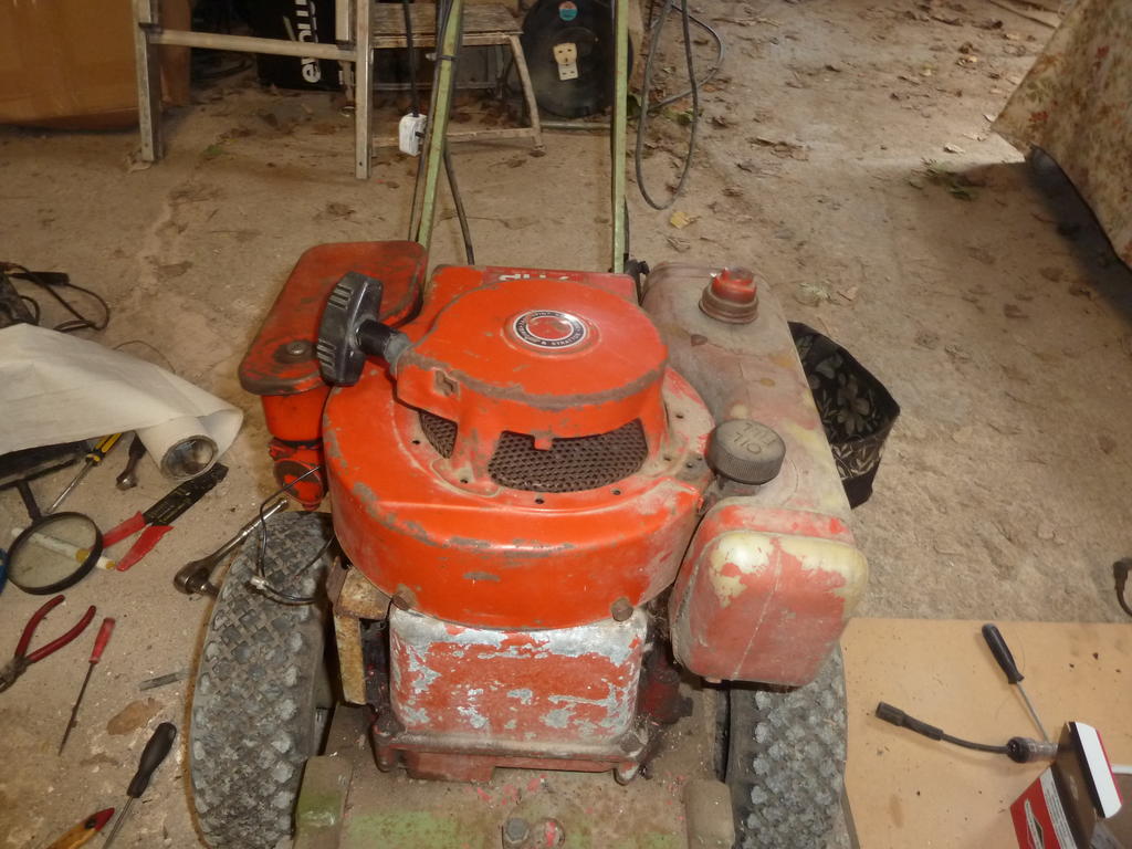
The Briggs & Stratton 3.5hp engine on my old hayter is now sadly on its way out.It uses a fair bit of oil and its now starting to rattle at the bottom end if used for too long. The carb could probably do with replacing too.
I don't if its worth stripping down and rebuilding the engine with new parts or getting a direct replacement?
I would welcome any thoughts on which would be the best solution.
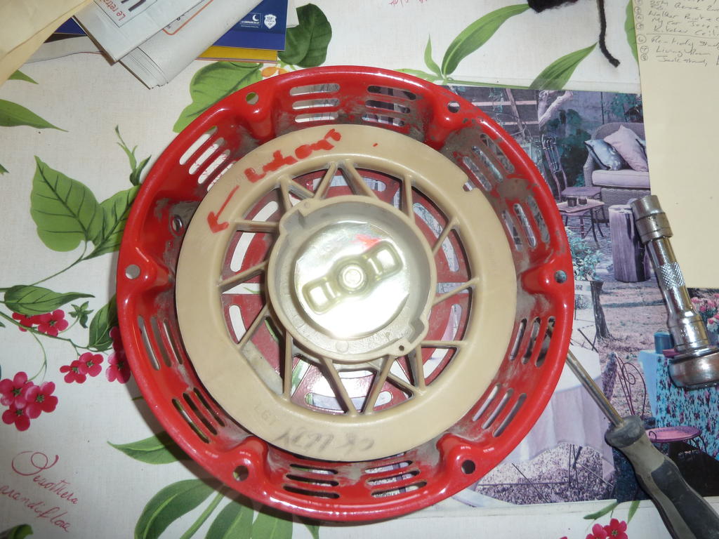
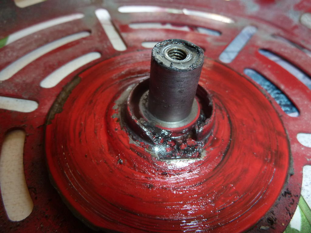
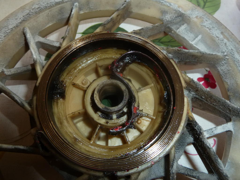
Good News!! I got brave yesterday and had a bit of free time so I took the recoil starter apart and manged to re-tension and got it working S1g is absolutely right (never doubted it) as th metal lip that holds the spring is not of a great quality so will look for a spare Honda one but all the same got it back together fitted new pull rope and back in business.
Also fitted new spark plug and hey presto fired up and ran quite well and compressor came up to pressure, Just needs a little fettling to get it running a bit smoother and I should be good to go. I will order a nw as well just it case I have any further issues but my thanks to everyone for their replies and help. Especially S1g I am currently reading through your other post at present and its very good!!!
Here are some pics of the starter if anyone needs them
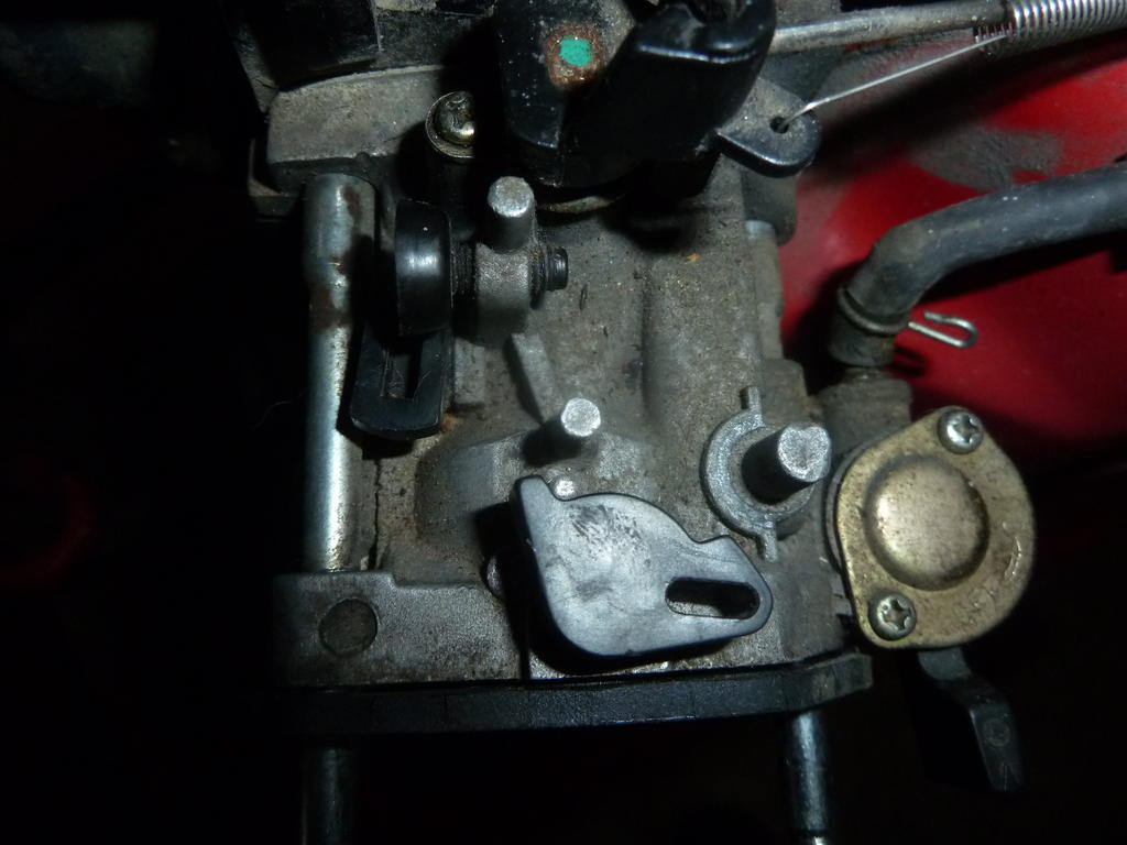
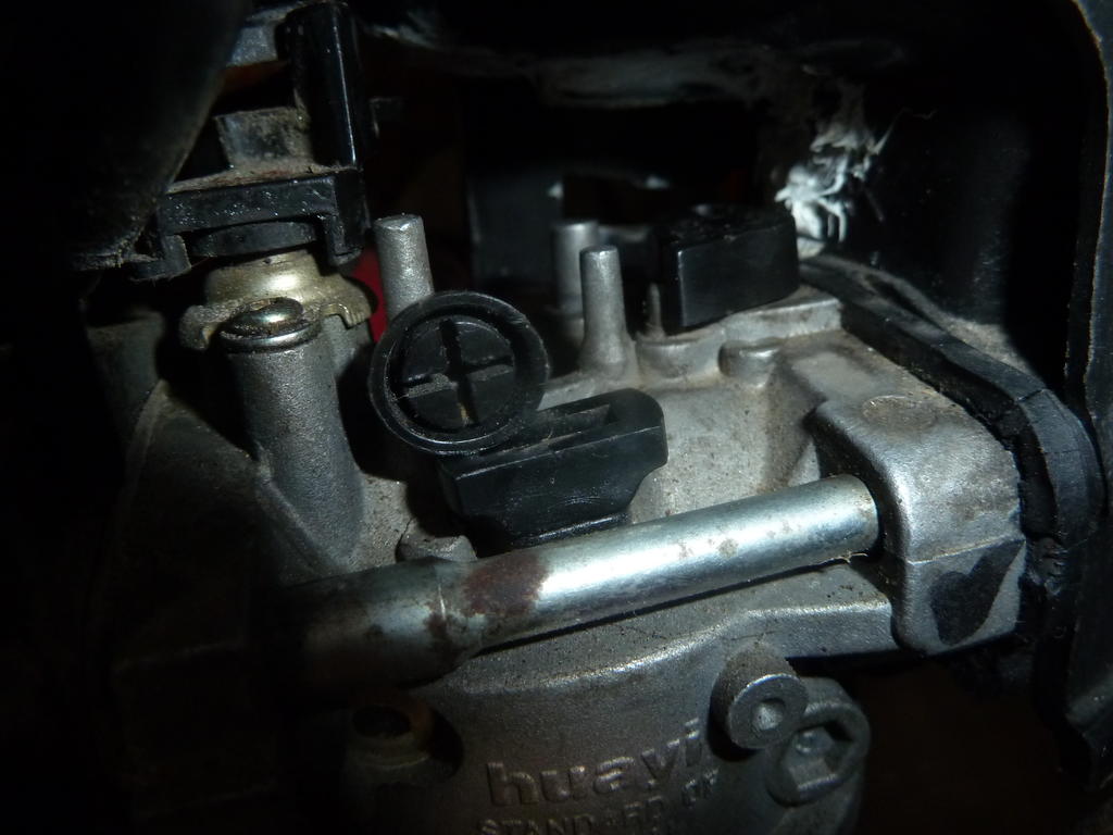
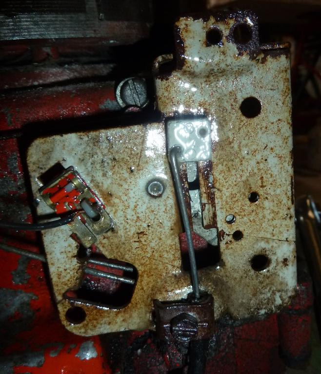
Hi I am talking about the rectangled shaped one nearest the engine on the left side of the photo nearer to the return spring and has a plastic screw attached to it.. As for the other towards the front bottom middle of the photo I think that is the choke as it operates the front butterfly. Just to add more to my woes the pull starter recoil spring has unwound and its the type with the 2 locking pawls. I don't know if there is a good easy method of re- tensioning it or if I have to strip it down!!
Either way I think getting another carb might be the easier route to go. Forgot to say yes I did take off the choke lever as that is broken and I am waiting for a replacement to arrive
From your photos I'm struggling to see what is damaged, to pop the carb off you should just undo the 2 M6 nuts on the air filter housing and one M6 bolt under the airfilter itself. Slide the choke and fuel lever away from the engine and disconnect the breather pipe. You will now be able to remove the housing. You will see a spacer plate, take note of which way round this is fitted. Pull the carb forward and rotate the throttle on it and the connecting linkage should pop out. Some have springs that also need disconnecting. The fuel pipe should be easy to lever upwards and I always plug it with the airfilter bolt. The carbs are available from China, the last one I bought was about £8.50 delivered. The gx340 carb will also fit and work if you can't find a GX 390 one. Gx240 are also the same physical size but can starve the bigger engines of fuel as the bore and jets are smaller. The black screw is a throttle stop, under the black square is an idle screw. sorry that I threw everything out but I've offered them to others before for free and no takers. I was giving up a unit so an awful lot of kit had to go.
Just looked on eBay, complete carb and gaskets are 8.58.if you're any where near Hereford I'd be happy to take a look, I used to overhaul about 5 GX Honda's a day, 6 days a week for about 10 years so have seen most problems.
Thanks for the reply and for your help. I was going to do a word doc with a couple of arrows pointing to the plastic lever I'm talking about (I can do this if my following explanation makes no sense!!
I took off the air filter housing yesterday and took a couple of photos of the top of the carb and the plastic lever on the top left I can move manually from the the 6 0 clock position to the 3 o clock position. I am not sure what position it should be in and if something else should be attached to it?
Dear S1g I just read about your arthritis and I sincerely emphasize and I hope things are not too bad with this cold weather. I was diagnosed with early onset arthritis in my wrists and can be a problem at times but I refuse to let it get the better of me until it does!!. I also hope you got a good price for your stuff in the end. Sometimes I give stuff away for recycling such as cordless tools and other bits and bobs that maybe of help to others.
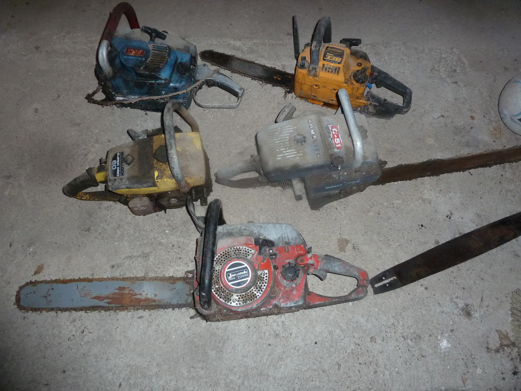
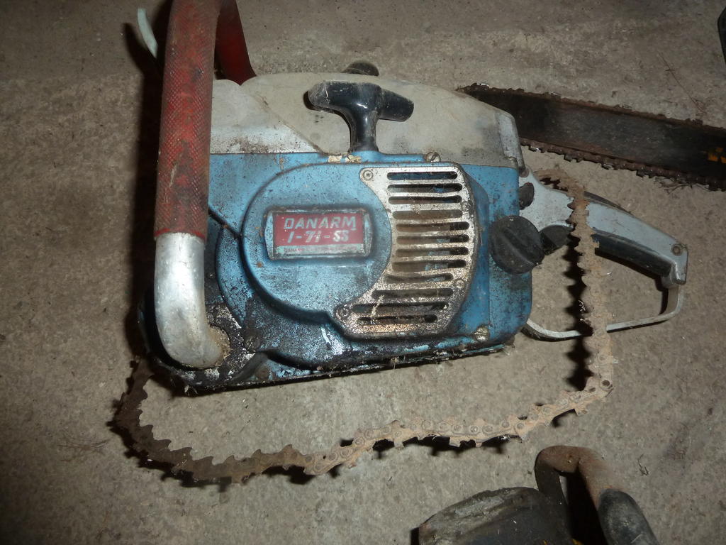
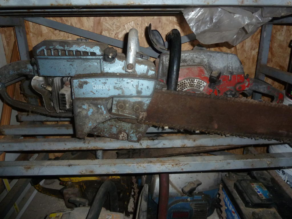
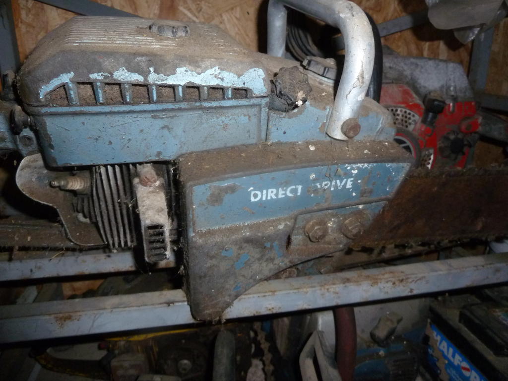
Parts are still easily attainable. The C stood for convertible because these saws often were used as power plants for post hole augers, ice augers, power generators and water pumps, they also had a clutch attachment to change from a direct drive chain to a gear reduction chain. These C series saw were way overbuilt structural and while heavy for the hp, were reliable over many more years than most saws. The C-51 was 77 cc's, the larger C-71 was 80.5 cc's and the C-91 was 85.5 cc's. Sand blasting with walnut hulls will prep the saw for paint and I recommend a cleaning in a alkaline based cleaner such as TSP or equivalent.
Many thanks for the information it is heavy LOL but I was given both the blue ones and the red one a few years back. I did get one running but due a major house renovation they have sat on the back burner for a while but th information you have given me is a big help and inspiration as well as the photos on here of course. Is TSP a thinners solvent ?
Thanks S1g for your reply and its a shame that you threw a load of stuff out as I probably would have made some space for it all in case other people needed a few bits. Especially as I Have just finished tidying up my little workshop!!! LOL.
Well I have have good look around for a fair few hours now and no luck but taking on board what you say and looking at it again. I think its part of the throttle linkage. In as much that the little plastic screw is adjustable I think maybe for tick over.and whatever is missing ie another pic of plastic that joins them up attaches to them togerther. Pretty much what you said above ( I think)
Found another way of looking but still a pain and that is trying to match info to amazon and ebay photos no luck as yet but will persevere. Just to add salt to the wound my pull start rope just snapped Damm!!!
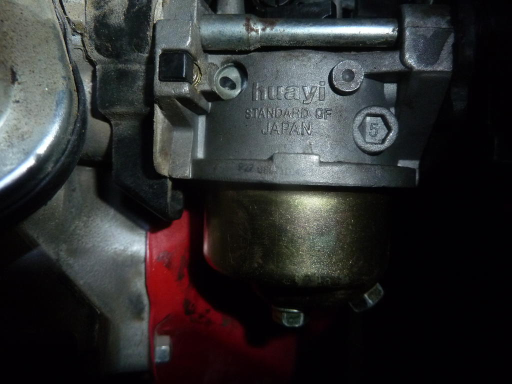
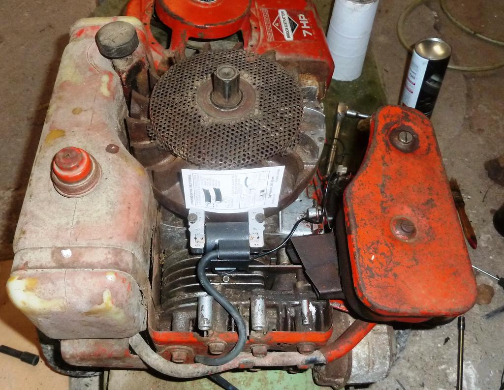
Woe is me sadly whilst moving home the guy helping me knocked over my compressor and the air filter housing broke along with some plastic levers on top of the carb. I know one is the choke but I am struggling to identify the other piece or how it works position wise as my download guide is not very good. Its a 13Hp 188f copy of the GX390 and I have attached a couple of photos so any help would be very welcome so that I can get it fixed. Many thanks in advance. Its the black part with what looks like a screw head in the second photo and the bit below it turns in 90 degrees
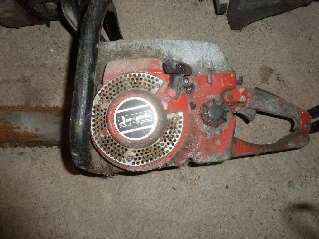
Wow that is stunning!! in fact I think I may have a similar one will check tomorrow in the meantime can anyone point in the direction of how to renovate a chainsaw as I have a couple that need sorting and I need to read up on how best to do this before I start
Pleased to have been of service! Your final problem and it's solution is interesting as, although I've not experienced it on s BS engine , I've seen it a few times on Tecumsehs; usually after they have been pressure washed during service. It would seem that electronic units can push enough down the kill wire to leak to ground if the conditions are right . In fact I've even experienced a " tingle " from a Tecumseh kill wire.
I hope that the rest of the job goes according to plan, but if not, there's plenty of Osprey related info available.
Many thanks again for all your help and your reply I hope it will also help other people in the future
Cant remember the exact figure but Magnetron units need around 350 rpm to produce a spark - considerably more than the old points and condenser set up , so you may not have lost the spark, just not pulling hard enough. If you have not already done so, remove the cutter belt until you have every thing working. On an Osprey there is a fair amount of inertia to overcome in the belt and cutter disc .
if the engine will only run on full or part choke you have a carburettor problem - not ignition ; time for a strip and clean.
Loosing your post - remember that we are into page three of a long thread!!!
Hiya,
I didn't lose the post but strange things were definitely happening as I also had to reset my password last night. I do agree though its a long but brilliant thread and you have been an Absolute Superstar and I would like to send you a little something to say Thank you for all your help or make a donation to this site if you prefer.
In the meantime GOOD NEWS I re-checked through everything this morning and I think the problem was with the stop wire holder on the throttle body as I mentioned it is a little worn. I disconnected the wire and checked and found that I had spark again. So I cleaned up the holder, refitted the wire and made sure the holder was snug after refitting and so far it has started everytime on 6 seperate occassions. I had already cleaned out the carb earlier so I didn't think it was that but it is something I would like to overhaul in the future. I am know going to add a smalll video (hope the site takes it) so you can see and hear for yourself. Here goes!!! Sadly File too big even though I have zipped it Here is a photo of it running you can see the flywheel is not stationery. Happy to email the Video though!!!
I am not sure what happened to my other post last night as it seems to have disappeared so I am having to rewrite everything again but in word 1st just to be safe!! Plus I couldn’t load photos maybe the site rolled back???
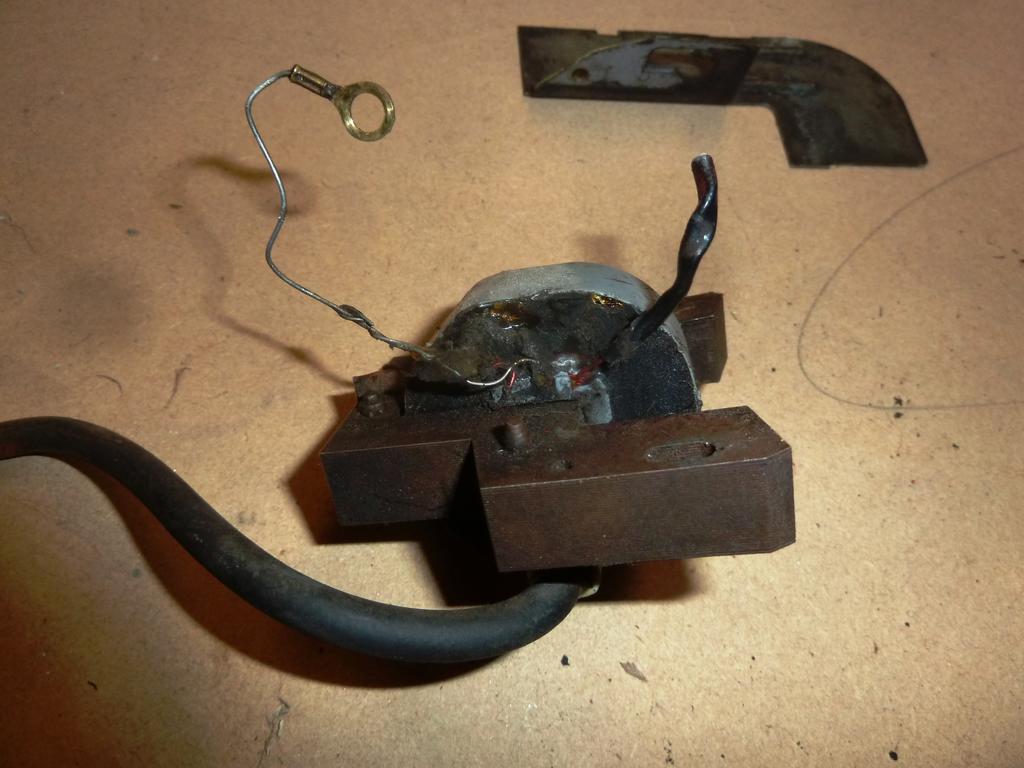
Anyway, Firstly I thought that that on the old coil that the wire with the ring connector on the left which was mounted on the post body via the coil securing bolt was Earth.
Secondly I thought that the wire on the right was possibly Positive and providing power to the condenser and points.
Then the other wire that that comes out from under the flywheel (wherever that’s connected to) goes directly to the stop switch.
Please forgive me and yes I agree I am a bit thick at times LOL!!!
So now I have cut off the right hand wire on the old coil which is what I thought was Positive and needing to be connected to the new Magnetron Coil. I realise now that since Wristpin has clarified this for me that this is not the case and I have removed the old coil. So on that note I think I have clarified my previous reply and don’t need to add anything further (I Hope LOL!!).
Well now onto the good news/bad news, I fitted the new coil as per instructions, set the timing up, connected the stop wire to the stop wire switch and low and behold I got a spark. Then I lost the spark I rechecked everything again 3 times over and got a spark which I captured on film which isn’t very exciting and I am not sure if I can post it up but happy to provide a copy if anyone wants one.
So at this point I had 4 or 5 consistent pulls with a spark so I refitted the plug. Put in some fresh fuel and tried starting it, After a few wrist breaking pulls it fired into life I then moved the throttle from full choke to run and it then died and I have lost spark again.
So now I am going to recheck everything again as I am not sure why I keep losing spark. Yippee photos have loaded, Middle pic is Timing being set up and the last is of the stop wire connector block on the throttle plate which is a bit of brass and plastic and not very good
Your Magnetron coil will produce a spark and run the engine with No wires connected to it - The spade terminal on the coil is for a connection to a Stop Switch to earth the coil and stop the engine.
To find the Stop Switch, follow the throttle cable from the handlebars down to where it joins the engine at the throttle plate. Somewhere on that plate you should see a wire : maybe attached with a small ring terminal to a threaded "post" with a nut or maybe pushed through a spring terminal. That is the Stop Switch. The wire wire can be traced back to under the flywheel and may safely be cut or removed together with the other wire .
You now need to provide a means of connecting your new coil to the stop switch. You could use the existing stop wire but to connect it to the coil you will have to find a suitable "lucar" female connector so it may be easier to use the new harness that came with the coil.
If your throttle plate has the threaded post, that is where you attach the ring terminal on your new wire . In that case connect the push on connector to the coil and route the wire with the ring connector to the stop switch. You can then cut off the spare wire from the coil connector . If the Stop Switch is of the spring terminal type you have a choice. Either proceed as above but snip off the ring connector, bare the wire and poke it under the spring or use the bare ended wire on your new harness to make the connection between coil and switch and trim off the wire with the looped terminal.
What you are trying to achieve is one wire connecting the coil to the Stop Switch - all other wires may be safely removed.
Sorry for confusing matters as I had in my head that there was a positive wire that I needed to make a connection to I will comeback to this point later as I think it is very important but I have some news that I want to share
Many thanks for the help and look forward to hearing from you. Hopefully I can this done tomorrow and see if it will fire up!!!
On 23/04/2017 at 2:57 PM, Wristpin said:
By the look of the image your machine has points ignition, no trigger module between the left leg of the coil armature and the coil itself.
Plug caps. Comments have been made about these being the likely cause of failure. This is only likely to be the case if the original BS connector has been removed and replaced with an aftermarket cap. Again, from your image you appear to have the original connector and there's not a lot that can go wrong with those. Sometimes they have a simple rubber boot.
The only exterior things left to check is the kill switch on the throttle plate or the kill wire that goes to it. If all is OK there, you have a choice, either remove the flywheel and examine the points etc , or find a later BS Magnetron coil ( with suitable leg spacing) and fit that in place of yours - a ten minute job and a direct replacement using your existing flywheel without the need to remove it.
Personally I would do the latter as they are 99.9% reliable and obviate the need to ever remove the flywheel again.
On 07/05/2017 at 7:24 PM, Wristpin said:
The thin wire from the coil low tension windings goes under the flywheel to connect to the contact breaker points and condenser. (Under a tin cover) . Another thin wire comes from the points to the kill switch which is positioned adjacent to were the throttle cable is anchored. The action of closing the throttle past the idle causes that switch to connect the coil and points to earth , thereby killing the ignition.
On 06/06/2017 at 11:26 PM, Wristpin said:
It's a straight forward job. The Briggs Magnetron kit illustrated includes a new flywheel key and a blanking plug for the points breaker plunger hole. Obviously, to fit those the flywheel has to be removed . I have to own up to fitting many Magnetron coils without removing the flywheel and leaving the original key and points assembly in place with no apparent ill effects over a number of years.
The choice is yours.
On 07/06/2017 at 4:53 PM, Wristpin said:
The new coil armature requires setting up as follows. Turn the flywheel so that the magnets are furthest away from the coil . Pull the coil as far from the flywheel as the slots allow and pinch up one coil fixing screw. Rotate the flywheel so that the magnets are equally aligned with the coil armature legs. Place your gauge ( plastic or card ) between the armature legs and the flywheel. Release the screw that you tightened and the magnets will pull the coil onto the flywheel pinching the gauge . Tighten both screws and turn the flywheel to assist pulling the gauge out.
In the absence of the correct gauge, Briggs used to suggest two thicknesses of an outdated micro fiche.
I'm a bit confused by the wiring harness illustrated in your last post as it appears to have a two pin socket with one wire possibly being an earth. The normal set up for a Magnetron coil is one wire from the blade connector on the coil running to the engine stop switch on the throttle plate. That said, the coil in your post is unlike any BS coil that I've seen, but as four years have passed since retirement, perhaps things have changed. None of the wires that disappear under the flywheel are needed with a Magnetron coil but it may be easier to either disconnect the stop wire from the old condenser and take it straight to the blade / spade connector on the new coil or cut it off close to the points enclosure and do the same.. That way you don't have to make any changes at the stop switch end.
Many thanks for the reply. In the box there is a set of instructions which reads as follows: (I hope I have received the right part)
The stop switch assembly has 2 wires. 1 with a ring terminal and 1 with no terminal.
Connect the spade terminal to the spade terminal on the armature.
Select the appropriate wire for the type of stop terminal the engine uses.
Cut off the remaining wire and discard.
Tape the end of the wire with electrical tape.
So what I have done so far is connected the spade to spade on the new coil. I was hoping that I could just connect the the ring wire on the new coil to the body of the machine which mirrors the old one. But I still have to cut the wire that is currently connected to the old coil as I don't think I can disconnect it without trying to give it a good Yank and hoping for the best or remove the flywheel which I am trying to avoid. And as you say I may have to connect this wire to the new coil. I just hope that the other end of the connection is ok.


Rebuild or Renew?
in Pedestrian Operated Machines
Posted
Thanks Nigel for your reply I am tending to agree as the price of parts will probably make it uneconomical to rebuild!!