

Anglo Traction
-
Content Count
1,119 -
Joined
-
Last visited
-
Days Won
143
Reputation Activity
-

 Anglo Traction got a reaction from nigel in Bits for my next Project
Slow progress lately. Have been pondering over the tank mounting design, but reckon I've found the answer.
The cooling fan assembly is now finished and the brass support plates nearly finished-
Just finished welding up the Reduction Gear mounting, so can start on prep for painting. Still working on Reserve tank hammering copper before I can finalise the mountings.
Fuel tank support mounts shown in this image-
Hopefully won't be too long before next update.
Regards
-
 Anglo Traction got a reaction from Alan in Bits for my next Project
Slow progress lately. Have been pondering over the tank mounting design, but reckon I've found the answer.
The cooling fan assembly is now finished and the brass support plates nearly finished-
Just finished welding up the Reduction Gear mounting, so can start on prep for painting. Still working on Reserve tank hammering copper before I can finalise the mountings.
Fuel tank support mounts shown in this image-
Hopefully won't be too long before next update.
Regards
-
 Anglo Traction got a reaction from nigel in Bits for my next Project
Finished making the (12) 6BA Bronze bolts and brass nuts for the Fan Shaft bearing/grease point housings over the last weekend and now trial assembled on the unit. All good-
-
Anglo Traction got a reaction from Alan in Bits for my next Project
Finished making the (12) 6BA Bronze bolts and brass nuts for the Fan Shaft bearing/grease point housings over the last weekend and now trial assembled on the unit. All good-
-
 Anglo Traction got a reaction from anotherblowngasket in 1972 Genset
Another little used refurb challenge from the machinery graveyard. Not very old, but worth cleaning up.
Hoping the Generator part is ok as it's totally enclosed.
Engine is very good, turns over smoothly, has clean oil and all there. I'm loving the heavy duty Spark Plug Suppressor Cover and Lead . Even the anti-vibration mounts are good.
It look's like a GD Mountfield branded Model, as it has a very nice Decal-
Looking forward to doing this one.
-
Anglo Traction got a reaction from anotherblowngasket in Conyers Generator 24322
Hello David, Welcome. Hopefully you will have success in your research of Conyers. I have seen several products with their name from the 60s>.
Your engine is a Briggs and Stratton, possibly 3hp , or even 4hp. You can obtain all the parts lists and opersting manuals based on the Model, Spec and Serial numbers stamped into the engine cowling right next to the Governor adjusting screw/Rod behind the Air Filter in your posted image.
I refurbished a '72' Genset some years back with the same engine and it's progress was logged in this section of the forum. If it is of any help, here is a link- 72 Genset
If you need any help with the engine, just post it here. Afraid I can't help with the generating part, as I'm not familiar with it.
Regards.
-
Anglo Traction got a reaction from nigel in Bits for my next Project
Many thanks for the comments. Sorry for being quiet for a while. Have been busy when able. Lots of decision making on design and machine time, but seem to produce little visually.
The Tank Cartridges were set up for drilling and tapping. Had to obtain a metre of 10mm studding to make the fixings, as they're quite tall-
Luckily the igniter percussion inserts drilled out ok, then tapped both bases 1/8"BSP for the fittings.
The fuel taps were done as per previous post, so just the Air Valve to design and make. Shown in next image on the left-
The left one shows the top of the reserve tank and the right shows the base of the main tank.
Next job was the fan shaft layout, bearing housings and 'Screw Down Grease Cups'. I had the latter vintage cups, but had to make the housings for them out of cast bronze bar.
Made a lot of work for myself milling to shape just to form the platforms to screw the cups into-
Finished them on the lathe so that I could fit a short piece of brass tube between them as a seal against water ingress-
Cheated a bit with these, as I'm hard soldering them to large flat brass washers to make the flange for bolting through and will match (in size, not colour) the ball bearing housings also machined from solid-
So here is the basic assembly/layout of the fan shaft and now about to start on the sprocket mount and fan/blades-
Regards
-
Anglo Traction got a reaction from Alan in Bits for my next Project
Many thanks for the comments. Sorry for being quiet for a while. Have been busy when able. Lots of decision making on design and machine time, but seem to produce little visually.
The Tank Cartridges were set up for drilling and tapping. Had to obtain a metre of 10mm studding to make the fixings, as they're quite tall-
Luckily the igniter percussion inserts drilled out ok, then tapped both bases 1/8"BSP for the fittings.
The fuel taps were done as per previous post, so just the Air Valve to design and make. Shown in next image on the left-
The left one shows the top of the reserve tank and the right shows the base of the main tank.
Next job was the fan shaft layout, bearing housings and 'Screw Down Grease Cups'. I had the latter vintage cups, but had to make the housings for them out of cast bronze bar.
Made a lot of work for myself milling to shape just to form the platforms to screw the cups into-
Finished them on the lathe so that I could fit a short piece of brass tube between them as a seal against water ingress-
Cheated a bit with these, as I'm hard soldering them to large flat brass washers to make the flange for bolting through and will match (in size, not colour) the ball bearing housings also machined from solid-
So here is the basic assembly/layout of the fan shaft and now about to start on the sprocket mount and fan/blades-
Regards
-
 Anglo Traction reacted to Aiberdonian in Bits for my next Project
I'm still following this thread and must say how much I admire your skill and patience in making such beautiful things like these taps.
Keep up the good work.
-
Anglo Traction got a reaction from nigel in Bits for my next Project
Finished the Fuel Taps. Lots of different set-ups and operations required. Did much of the work while still part of the parent brass rod. Cross drilling 3/8"(9.55mm)-
I wanted the tap levers opposed to eachother for access (in the off position), so had to be careful when it came to drilling through with the tapered plugs fitted-
.
The Tap's cam limit plates had to be soldered together, then to a stub of brass for machining to shape using a rotary table-
When as much work as possible was done, I cut them away from the parent bar and 'Silver Soldered' the pipe connection rods to the Tap bodies.
All the fiitings are for 3/16" (4.75mm) copper pipe. The tap tapers are 'pulled in' using the correct 'Thackery' coil spring washers and provides just the right amount of resistance-
A light polish and just need proper 1/16" Split (cotter) Pins to finish off. Maybe blend the joints. Happy with this first time job for me.
Regards
-
Anglo Traction got a reaction from Alan in Bits for my next Project
Finished the Fuel Taps. Lots of different set-ups and operations required. Did much of the work while still part of the parent brass rod. Cross drilling 3/8"(9.55mm)-
I wanted the tap levers opposed to eachother for access (in the off position), so had to be careful when it came to drilling through with the tapered plugs fitted-
.
The Tap's cam limit plates had to be soldered together, then to a stub of brass for machining to shape using a rotary table-
When as much work as possible was done, I cut them away from the parent bar and 'Silver Soldered' the pipe connection rods to the Tap bodies.
All the fiitings are for 3/16" (4.75mm) copper pipe. The tap tapers are 'pulled in' using the correct 'Thackery' coil spring washers and provides just the right amount of resistance-
A light polish and just need proper 1/16" Split (cotter) Pins to finish off. Maybe blend the joints. Happy with this first time job for me.
Regards
-
 Anglo Traction got a reaction from Cub Cadet in Bits for my next Project
Not a lot of progress, what with the cold spell of the last 3 weeks. Confined myself in the warmer environment of the Lounge. Too cold in the workshop.
Have been designing and drawing up the Fuel fittings I require. Nothing 'off the shelf' will suit, so making my own and using a 1950s ATCO Pet Cock as a guide.
Got some Lathe time in over last few days and started turning up a Taper Reamer blank, then a first Pet Cock plug at the same settings. Got to produce several of these so I have a stock.
The taper angle is 7 degrees inclusive . The little levers that screw into the plug are threaded 5/32" Whitworth, so making them the same -
Had to keep to Imperial, not easy to mix metric on these, plus I have been asked to reproduce an old Pet Cock style for a restoration.
Ready to part off the finished plug from the rod and make the next one now.
The reamer blank is next to finish machining the cutting edges, then harden, temper and hone.
Quite pleased really, as the new plug actually fits perfectly in the old tap body, so I got the angle right.
Regards.
-
Anglo Traction got a reaction from Cub Cadet in Bits for my next Project
Thank you Gents for your positive comments. Lot of work sorting the Reduction Unit design set up.
I needed to provide stanchions for the tank(s) support and location, bearing support for the fan drive, Pto clutch lever mount point and lubricator positions, all in one area.
I decided on brass plates for extending up to fan shaft line. Started with an old 12 inch (305mm) square plate shown during marking out-
After lot of cutting and careful drilling time, I was able to fit it and began the stiffening with bracing layout and fittng the welded and shaped stanchions.
Lubrication connections made to fit into the large brass bearings, then made/fitted the mountings for the Lubricators.
These Lubricators were found in an old barn in France about 15 years ago and are shown in the very first image of this Topic. Had to anneal the thick walled copper pipes, shaped to fit using a home made tube bender also shown in the image below-
Had to use incompatible metals in this unit (electrolytic/galvanic reaction risk), so will have to be careful to seal the mating surfaces of the Aluminium and Brass parts, even though they will be polished and lacquered.
Hoping to get this unit''s mounting plate/support welded up soon.
Regards and wishing all a Happy New Year
-
Anglo Traction got a reaction from Cub Cadet in Bits for my next Project
Had some lathe and milling machine time in recently. Started on the wheel for the front caster. Had barely enough 40mm dia EN8 Steel to make the hub and leave enough for the drive coupling.
Had to work really close to the chuck jaws, which was going fine with light feed, then I noticed the 'in-feed' movement of the parting tool went 'light' and easier !. I withdrew the tool and found it had failed !.
As I bought it in a modestly priced set 38 years ago and just lightly stoned the cutting edge now and again, it has served me very well-
I finished off with a narrow HSS type with no issues.
Indexed and drilled for the spokes on the Mill with barely 1.5mm clearance between rotary table wheel and chuck ! -
Also added an angled grease point and made the bronze bushes to be pressed in later-
I decided to keep the original engine output drive clutch bell and make a driven plate to replace the original Mower Clutch plates to form a coupling.
This would allow for any tiny misalignment of the engine and the reducton unit.
The load transfered through this part will be much less than it was orignally handling in a Mower, but I wanted it to be efficient and reliable.
Ordered a 105mm x 4mm laser cut mild Steel disc and meanwhile, I made 6 bronze wear pads -
The slitting saw used is only 0.0125" (0.3mm) thick. These pads were soldered to the dog spokes of the plate where they will contact the recesses in the clutch bell.
The plate was then set up to drill the 6 HT fixing screws to the boss-
Once I had cut the keyway in the boss, I pressed the plate with the drilled and countersunk holes onto the boss and finished fitting the screws. i need to file out the keyway in the plate to depth.
The bell drive recesses needed weld metal added where they were worn from mowing since 1954, but were not bad at all -
The caster wheel is at the final assembly stage. My reasons for using surplus thick walled steel tubing for the rim left over from my previous Water Cart wheel making becomes clear.
It all fits and allows me to re-use the wheel jig for accurate assembly ! -
Regards
-
Anglo Traction got a reaction from nigel in Bits for my next Project
Not a lot of progress, what with the cold spell of the last 3 weeks. Confined myself in the warmer environment of the Lounge. Too cold in the workshop.
Have been designing and drawing up the Fuel fittings I require. Nothing 'off the shelf' will suit, so making my own and using a 1950s ATCO Pet Cock as a guide.
Got some Lathe time in over last few days and started turning up a Taper Reamer blank, then a first Pet Cock plug at the same settings. Got to produce several of these so I have a stock.
The taper angle is 7 degrees inclusive . The little levers that screw into the plug are threaded 5/32" Whitworth, so making them the same -
Had to keep to Imperial, not easy to mix metric on these, plus I have been asked to reproduce an old Pet Cock style for a restoration.
Ready to part off the finished plug from the rod and make the next one now.
The reamer blank is next to finish machining the cutting edges, then harden, temper and hone.
Quite pleased really, as the new plug actually fits perfectly in the old tap body, so I got the angle right.
Regards.
-
Anglo Traction got a reaction from Alan in Bits for my next Project
Thank you Gents for your positive comments. Lot of work sorting the Reduction Unit design set up.
I needed to provide stanchions for the tank(s) support and location, bearing support for the fan drive, Pto clutch lever mount point and lubricator positions, all in one area.
I decided on brass plates for extending up to fan shaft line. Started with an old 12 inch (305mm) square plate shown during marking out-
After lot of cutting and careful drilling time, I was able to fit it and began the stiffening with bracing layout and fittng the welded and shaped stanchions.
Lubrication connections made to fit into the large brass bearings, then made/fitted the mountings for the Lubricators.
These Lubricators were found in an old barn in France about 15 years ago and are shown in the very first image of this Topic. Had to anneal the thick walled copper pipes, shaped to fit using a home made tube bender also shown in the image below-
Had to use incompatible metals in this unit (electrolytic/galvanic reaction risk), so will have to be careful to seal the mating surfaces of the Aluminium and Brass parts, even though they will be polished and lacquered.
Hoping to get this unit''s mounting plate/support welded up soon.
Regards and wishing all a Happy New Year
-
Anglo Traction got a reaction from nigel in Bits for my next Project
Thank you Gents for your positive comments. Lot of work sorting the Reduction Unit design set up.
I needed to provide stanchions for the tank(s) support and location, bearing support for the fan drive, Pto clutch lever mount point and lubricator positions, all in one area.
I decided on brass plates for extending up to fan shaft line. Started with an old 12 inch (305mm) square plate shown during marking out-
After lot of cutting and careful drilling time, I was able to fit it and began the stiffening with bracing layout and fittng the welded and shaped stanchions.
Lubrication connections made to fit into the large brass bearings, then made/fitted the mountings for the Lubricators.
These Lubricators were found in an old barn in France about 15 years ago and are shown in the very first image of this Topic. Had to anneal the thick walled copper pipes, shaped to fit using a home made tube bender also shown in the image below-
Had to use incompatible metals in this unit (electrolytic/galvanic reaction risk), so will have to be careful to seal the mating surfaces of the Aluminium and Brass parts, even though they will be polished and lacquered.
Hoping to get this unit''s mounting plate/support welded up soon.
Regards and wishing all a Happy New Year
-
-
Anglo Traction reacted to nigel in Bits for my next Project
I wish I had 10% of your talent Richard 👍
-
-
Anglo Traction got a reaction from Cub Cadet in Eclipse Sprayer
Had an opportunity to obtain this Sprayer in exchange for a contribution to a Charity.
It was in a sad state after being exposed to sun light and temperature extremes for many years.
The all important nozzle was missing, a large dent in the base and the wooden handles were very dry and cracked with shrinkage.
Solid Brass and riveted/soldered joints, the item weighs 2.060 kgs dry.
Fortunately, the Museum Curator had another near complete example, so I was able to borrow the nozzle parts for reproduction.
Found the thread form was 1/8" BSP parallel, but several thousanths of an inch under size!.
The main nozzle part wasn't difficult to produce, but had to make a reamer to form the minute taper of the outlet and produced the atomiser/restricter which was complicated-
The Air Pump leather washer was tired and still fairly good, but made a new one from slightly thicker raw leather -
Thie plunger is obviously tighter, but needs to relax and bed in and is easing with use. Being a pressure vessel, the control tap and pressure relief valve are all clean a working well-
The hardwood plunger handle was so dry, it soaked up 20ml of raw linseed oil on the first feed. Another 5ml satified it's thirst and the cracks slowly closed up over a week.
All back together and waiting for an acid, then soap, then soda washout, the latter to neutralise the ph level to 7.-
Ignore the extra 'Thumb Nut' on the back of the horizontal handle, it is one I made for the museum example that was missing it. Bit of ageing and it will merge in well.
My example may well be a 'Suds Pump' cutting oil feed for my Myford to save on electricity. So, a very nice piece of early 1950s quality re purposed.
Regards
-
Anglo Traction got a reaction from Cub Cadet in Bits for my next Project
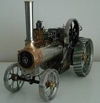
I've been designing/making several parts over the last month. decided to go for rope pull start on the engine, simpler job and I could use an old pulley that was used originally on the 'Yellow Mower Challenge ATCO' back in around 1959. The pulley is a 4" Picador with angled slots cut in and filed for the rope knotted end. I had to make the brass retaining bolt once I'd identified the flywheel nut thread form (9/16" x 20tpi BSC). It is fairly quick to remove to gain access to the ignition points/mag-
The mahogany bumper blocks were added so as to allow a short overhang of the pulley/flywheel and puts the engine/mount centre line over the rear axle.
The finished engine mount has some embelishments added in the form of brass straps-
Working on the fuel tanks stand/mount presently and have finished bashing the copper to shape for the top of the main fuel tank-
I have more work to do on it before soldering up and make the reserve tank.
Reduction gear mounts next and the drive etc for the cooling fan.
Regards
-
Anglo Traction reacted to Twinsport in Zündapp 600 generating set
Greetings from Denmark,
I think we need more german stuff here .
I have this portable (well - 305 kilos, no wheels) generator as used by the german forces in WW2. They were built from 1940 well into the 1950's. This particular one is from 1944, which can be seen from many details made from steel, which, on the earlier versions were made from aluminium.
The generator set delivers 7,5kW on three phases. The engine is a 600cc Zündapp boxer, which makes it very smooth even at full load. This one is fully functional, but most have defective generators these days.
/Steen
Markings
-
Anglo Traction got a reaction from Alan in Eclipse Sprayer
Had an opportunity to obtain this Sprayer in exchange for a contribution to a Charity.
It was in a sad state after being exposed to sun light and temperature extremes for many years.
The all important nozzle was missing, a large dent in the base and the wooden handles were very dry and cracked with shrinkage.
Solid Brass and riveted/soldered joints, the item weighs 2.060 kgs dry.
Fortunately, the Museum Curator had another near complete example, so I was able to borrow the nozzle parts for reproduction.
Found the thread form was 1/8" BSP parallel, but several thousanths of an inch under size!.
The main nozzle part wasn't difficult to produce, but had to make a reamer to form the minute taper of the outlet and produced the atomiser/restricter which was complicated-
The Air Pump leather washer was tired and still fairly good, but made a new one from slightly thicker raw leather -
Thie plunger is obviously tighter, but needs to relax and bed in and is easing with use. Being a pressure vessel, the control tap and pressure relief valve are all clean a working well-
The hardwood plunger handle was so dry, it soaked up 20ml of raw linseed oil on the first feed. Another 5ml satified it's thirst and the cracks slowly closed up over a week.
All back together and waiting for an acid, then soap, then soda washout, the latter to neutralise the ph level to 7.-
Ignore the extra 'Thumb Nut' on the back of the horizontal handle, it is one I made for the museum example that was missing it. Bit of ageing and it will merge in well.
My example may well be a 'Suds Pump' cutting oil feed for my Myford to save on electricity. So, a very nice piece of early 1950s quality re purposed.
Regards