| |
-
Venue looks nice but you don't look normal Norman.
-
Should have added these photo's to my edit of the 24th August. Winch in use while pulling / cutting trees down on friends land a few years ago.
-
Thanks Richard. Camera doesn't always behave. A bit like me.
-
I liked it too Richard. Ditto your comments. The Selig lathe I rescued is more like 3 foot 6 inches, not 4 foot. Only guessed, a tape said otherwise.
-
Happy Birthday Joseph. Has dad started your little horse yet. ? You know you want one.
-
The blue lathe shown above is a 5" double height bed Drummond, circa 1912. The saddle and it's cross slide run on the lower bed ways, while the tailstock runs on the upper bed. More information here. "double-height bed"
-
Another little update after another delay. Too many things to do. Who said retired people have plenty of spare time. The hood catches which started off as 3/16" diameter car brake pad pins. An alloy sleeve pressed on, drilled 1/16" for a short piece of wire, then the domed head turned off.
1/2" ID alloy box section was pop rivited to the inside of the hood after drilling for the pins. A nut and bolt held it in place while drilling for the rivits.
Another 1/16" hole was drilled for the retaining R clip after careful measurement to make sure it was in the correct place. It was. More measurement and head scratching then the excess was cut from the pins and the ends chamfered. When closing the hood the pins slide down slightly angled plates before popping into holes near the base. These plates can be seen on this earlier photo of the dash panel.
The pins are sprung into place by springs, what else, taken from AA size battery boxes. These were inserted into the alloy box first, then compressed with special tool which I carefully designed then made, allowing room for the pin to pass through. OK, a piece of scrap alloy with a slot filed in it did the job. It was a pig of a job to hold the compressed spring, hold the pin steady, and insert the R clip, while trying avoid it pinging off into the distance. If the R clip had been long enough to protude outside the alloy box it would have been easier. The clip can be seen to the left, the rivits to the right. A washer between the clip and spring would have been better but I gave up trying to fit one. Kept going awol.
The parts almost ready to be fitted.
Works as intended although just as easy to pull the bottom corners of the hood out slightly which releases the pins.
-
I think KNOW it would be too. Winches, rollers, lots of muscle power. A lot easier at John's.
-
Both the Drummond and Harrison are big and heavy Nigel. The Harrison looks the better option as more modern, but I don't know what price etc. I think the Showmans friend Steve might have more info. I don't have his or the owners phone numbers.
-
A few more bits, large and small, lurking in and around the various sheds near where the Selig lathe came from. Added with permission of the owner.
A large Drummond lathe about 6 foot long. No idea of the model, plus a hefty looking Harrison. Forgot to check the swing of these two. Not much room to get good photo's.
A wood turning lathe, band saw, and hidden under the blue tarps a wood planer. Can't remember what the green machine in front of it is.
A surface grinder and what we think is some sort of guillotine or maybe metal bender. This has a double ended V shaped blade which slides sideways.
Pillar drill and wood mortiser.
Lots of assorted wood planes and a nice boxed Record 405 multi plane. I think the owner said there were more of these, or similar, stored away.
And finally three large stationary engines. A Bamford and two of which I have forgotten the make.
Some of the larger machinery look as if they were installed first, then the sheds build around them. Lots more smaller bits and pieces scattered everywhere. If anyone interested in any of the above, just shout.
-
-
The Brinley from John's had a Brinley sticker on it Chris. It was the one you found under the Morris Minor bonnet at the back corner of the workshop shed. Photo's of it on here somewhere.
-
Correct Norm. I have one too. Same make but slightly different to yours. Mine came from John's and is missing the rubber.
-
Thanks all. Would never have thought of that. Because of all the lathes and machinery in the sheds, I assumed that it was some sort of workshop measuring or setting device, but can see it's use now. The only guns I have handled were toy pop guns in my not so old days.
-
Found while digging around in the shed after collecting the Selig lathe. Just over 3" long. The small knob moves the end section sideways. The larger knob raises or lowers. Not much movement of both sections. This was the only part in a small box although it is obviously part of a kit. No name or numbers.
-
Up and running by January. No chance. About 4 foot long. Brought all the treadle parts home but would motorize it. Still need to finish the Drummond round bed which is well on the way. Plus a few alterations to Half a Horse after it's first runs at Beddenden.
-
Found recently by the Showman and friend Steve Dibnah in a shed and now residing in my garage. A 4" x 24" Selig Sonnenthal Lathe. From information found on the WWW, these were made from 1880 to 1910, so this young man is at least 108 years old. A future project which will need a bit of work. Just had a quick look so far and found all parts move without effort. No rust as it was well protected by a covering of sawdust.
Complete with cast legs and treadle assembly, a pile of 17 change wheels plus more on the lathe and various other parts.
A few photo's after returning home. Don't know what the weight of everything was, but the car didn't bounce much.
And a few of the various parts.
And the lathe on the garage floor, for now.
-
Happy Birthday Andrew. Have a good one.
-
Looks like I have deleted the photo's I had. No sign of them anywhere.
Found them now while looking for something else, as usual.
-
Looks familier Chris. From John's ?. Remember the winch in the small shed next to the house. Similar to Iain's orange painted one. I'll have a dig through my photo's.
-
Santa Norm. He was practicing for next Xmas and thought it was a strange looking house chimney. He was stuck at the bottom.
-
And ditto from me. Thanks Kevin, Ethan and everyone involved. A great show.
-
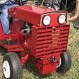
I think Alan liked this little homemade tractor.
I did Chris, I did, a LOT. Didn't know you were spying on me with your camera though.
-
-
|
|