

Cub Cadet
-
Content Count
485 -
Joined
-
Last visited
-
Days Won
21
Reputation Activity
-


-

 Cub Cadet reacted to Anglo Traction in Bits for my next Project
Slow progress, but now have a finished rolling chassis that I can assemble the important bits on. Engine was the first bit to go on-
Still working on the chain drive and guards on the pump side, with the 'idler'- tensioner set up being the current challenge to design and fit-
Clutch Lever has been a problem, but have now finalised the handle shape and will be cut from 10mm thick block of brass. Will also have a lock lever fitted-
Lots going on with other things, but will try and improve update regularity.
Regards
-
Cub Cadet reacted to Anglo Traction in Bits for my next Project
Making slow progress, hence the belated update. Have been painting, varnishing and making Nuts n Bolts. Sorted the drive chain link problem, so now making up the chain guard wth brackets-
Ensuring clearances and fixing points were ok. 2 more lower brackets to make and I can move on to the clutch lever and outer cable fitting. Wheels are now shiney black gloss.
Regards
-
Cub Cadet reacted to Anglo Traction in Bits for my next Project
Thanks Alan, Been preoccupied with lots of small jobs and pulling together two of the three sections of this project.
The middle section (reduction gear unit) has taken a lot of time and work, as it includes the fuel tanks. They are finished, lacquered, mounted and the fuel gauge nestles between them-
Still incomplete middle section where I have to make up the cable and lever system for operating the clutch/brake shoes. The last job will be to fill the Reduction gear unit with oil -
All the brass/bronze work has been polished and lacquered as assembly progressed, with the exception of the engine cowling, as I now have some clear gloss VHT Lacquer for that.
output/fan drive sprocket modified to fit onto a woodruf key and locked in place with a grub screw
Finalised the location of the modified throttle lever and cable route, which keeps it neat, tidy and handy location. Lever and cable joints are watertight.
Although I will have to change the Carb Air inlet and Choke layout to prevent water ingress-
Tempted to start the engine for a run soon to check how it sounds with the exhaust. Has a lovely bright blue spark at the plug and the timing is spot on.
Mahogany planks being treated prior to fitting and will be yacht varnished after. Pump drive and location of it is a bit of a headache, but working on it-
Regards.
-
Cub Cadet reacted to Anglo Traction in Bits for my next Project
Well, later than planned, I've made much progress on the fuel tanks and the mounts. Still more copper tapping to final size, but nearly there with both tanks.
Reserve fuel tap mounting boss finished and light press fit ready for silver soldering shown here-
Have been making the straps, platforms and retaining rings., the latter from 1/4' x 1/4" x 1/16" brass angle. cut, bent and silver soldered to produce 18 sided rings-
Eventually the concept in my head and on paper materialised into this -
Pleased with the strength and rigidity on the base and supports for the tanks (the lines drawn on the copper parts are for more dressing out of irregularities for a better fit.
A little fettling of the fit around the upper cradles/straps.
Working on the Fuel Gauge parts at the moment. Will then return to the reduction gear unit and final location of it on the chassis
-
Cub Cadet reacted to Anglo Traction in Bits for my next Project
Slow progress lately. Have been pondering over the tank mounting design, but reckon I've found the answer.
The cooling fan assembly is now finished and the brass support plates nearly finished-
Just finished welding up the Reduction Gear mounting, so can start on prep for painting. Still working on Reserve tank hammering copper before I can finalise the mountings.
Fuel tank support mounts shown in this image-
Hopefully won't be too long before next update.
Regards
-
Cub Cadet reacted to Anglo Traction in Bits for my next Project
Finished making the (12) 6BA Bronze bolts and brass nuts for the Fan Shaft bearing/grease point housings over the last weekend and now trial assembled on the unit. All good-
-
Cub Cadet reacted to Anglo Traction in Bits for my next Project
Many thanks for the comments. Sorry for being quiet for a while. Have been busy when able. Lots of decision making on design and machine time, but seem to produce little visually.
The Tank Cartridges were set up for drilling and tapping. Had to obtain a metre of 10mm studding to make the fixings, as they're quite tall-
Luckily the igniter percussion inserts drilled out ok, then tapped both bases 1/8"BSP for the fittings.
The fuel taps were done as per previous post, so then just the Air Valve to design and make. Shown in next image on the left-
The left one shows the top of the reserve tank and the right shows the base of the main tank.
Next job was the fan shaft layout, bearing housings and 'Screw Down Grease Cups'. I had the latter vintage cups, but had to make the housings for them out of cast bronze bar.
Made a lot of work for myself milling to shape just to form the platforms to screw the cups into-
Finished them on the lathe so that I could fit a short piece of brass tube between them as a seal against water ingress-
Cheated a bit with these, as I'm hard soldering them to large flat brass washers to make the flange for bolting through and will match (in size, not colour) the ball bearing housings also machined from solid-
So here is the basic assembly/layout of the fan shaft and now about to start on the sprocket mount and fan/blades-
Regards
-
Cub Cadet reacted to Anglo Traction in Bits for my next Project
Finished the Fuel Taps. Lots of different set-ups and operations required. Did much of the work while still part of the parent brass rod. Cross drilling 3/8"(9.55mm)-
I wanted the tap levers opposed to eachother for access (in the off position), so had to be careful when it came to drilling through with the tapered plugs fitted-
.
The Tap's cam limit plates had to be soldered together, then to a stub of brass for machining to shape using a rotary table-
When as much work as possible was done, I cut them away from the parent bar and 'Silver Soldered' the pipe connection rods to the Tap bodies.
All the fiitings are for 3/16" (4.75mm) copper pipe. The tap tapers are 'pulled in' using the correct 'Thackery' coil spring washers and provides just the right amount of resistance-
A light polish and just need proper 1/16" Split (cotter) Pins to finish off. Maybe blend the joints. Happy with this first time job for me.
Regards
-
Cub Cadet reacted to Joseph in Landmaster Ride On Project
It's been a while since I've posted on here, so I thought I would make a new thread about a project that I've started recently and try to update it regularly, hopefully it might be of interest to a few people.
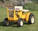
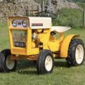
This machine is a bit different to most of our collection - it is a little Landmaster Super Deluxe Ride on (I believe is what they were marketed as). I bought this in April this year, having had it pointed out to us by a fellow forum member (thanks again Paul). I barely touched the tractor for a few months due to studying for exams, but since there is a couple of weeks left of the summer holidays and some of our other projects have slowed down I have finally gotten around to looking at this. Here are a couple of pictures of the tractor when we picked it up.
This machine was a COVID project for the previous owner, and he made a number of modifications to the tractor. The biggest change is probably the engine swap that it has had. I am under the impression that it originally had a 4hp Briggs in it, but the previous owner said that he struggled to get parts for it, so he swapped in this 5hp model of a similar series. I have used the numbers on the engine tin to date the engine to the 15th of November 1978. From what I've seen from Paul's thread of the restoration of his Landmaster, the tractor itself was made in 1966, so the engine is 12 years younger. The previous owner told me he had it running and driving 18 months before he sold it, so a bit longer now but hopefully the engine will run without many issues. Other modifications include the chute on the side of the deck, which I quickly removed, pneumatic tyres, extensive deck repairs and the handlebars appear to have been cut off, and remounted upside-down using a T-joint. It has also been repainted, with some parts having the wrong colour on it such as the front wheels which should be white, and the engine could do with a lick of paint too, which should be white. The quality of the paint isn't the best, so probably needs some work in future
Fast forward to a couple of days ago, when I began to look at this machine in more detail. I removed the handle bars and bonnet to gain better access to the engine, which seemed far more fiddly than it should have - this seems to be a pattern on this machine unfortunately! This wasn't helped by all imperial fixings being replaced with metric bolts of varying sizes.
With these parts off I drained the fuel, as on this engine the carb is mounted on the fuel tank such that the tank appears to act as a fuel bowl - plus I didn't fancy pulling old fuel through the fuel system when I checked for a spark.
We bought this pump years ago and have never used it for anything, beats syphoning the fuel by nearly drinking it. Glad I did drain it though, I wasn't very keen on how the old fuel looked or the sediment that was suspended in it.
With the fuel drained I was happy to pull the engine over, so I used our spark plug tester to check for a spark, and as you can see below it did indeed have a spark so that's one less possible issues
While I had the spark plug out (and it was easier to pull over) I took the opportunity to identify what all of the controls do. I don't have access to any sort of manual for the tractor, only for the engine so before this I wasn't sure how everything works. This uncovered a couple of issues, mainly that both the deck and drive belts coming off the engine pulley are not being disengaged enough when the clutch is pushed down, so I need to make some adjustments to allow the belts to slip when the deck is disengaged and the clutch pedal is pushed. The good news is that the brake appears to work, along with the forward-reverse gear change and 1st to 2nd.
This is as far as I have got so far, next step is probably going to be lifting the front of the tractor to get access to the belt tensioners on the underside of the machine and making some adjustments. I'll post again if and when I make more notable progress.
-
 Cub Cadet got a reaction from Mike in NC in O&R Tarpen tools
Nice! I've grown to like these O&R machines! Wish I could find one
-
Cub Cadet reacted to Anglo Traction in Bits for my next Project
Not a lot of progress, what with the cold spell of the last 3 weeks. Confined myself in the warmer environment of the Lounge. Too cold in the workshop.
Have been designing and drawing up the Fuel fittings I require. Nothing 'off the shelf' will suit, so making my own and using a 1950s ATCO Pet Cock as a guide (shown on the right).
Got some Lathe time in over last few days and started turning up a Taper Reamer blank, then a first Pet Cock plug at the same settings. Got to produce several of these so I have a stock.
The taper angle is 7 degrees inclusive . The little levers that screw into the plug are threaded 5/32" Whitworth, so making them the same -
Had to keep to Imperial, not easy to mix metric on these, plus I have been asked to reproduce an old Pet Cock style for a restoration.
Ready to part off the finished plug from the rod and make the next one now.
The reamer blank is next to finish machining the cutting edges, then harden, temper and hone.
Quite pleased really, as the new plug actually fits perfectly in the old tap body, so I got the angle right.
Regards.
-
Cub Cadet reacted to Anglo Traction in Bits for my next Project
Thank you Gents for your positive comments. Lot of work sorting the Reduction Unit design set up.
I needed to provide stanchions for the tank(s) support and location, bearing support for the fan drive, Pto clutch lever mount point and lubricator positions, all in one area.
I decided on brass plates for extending up to fan shaft line. Started with an old 12 inch (305mm) square plate shown during marking out-
After lot of cutting and careful drilling time, I was able to fit it and began the stiffening with bracing layout and fittng the welded and shaped stanchions.
Lubrication connections made to fit into the large brass bearings, then made/fitted the mountings for the Lubricators.
These Lubricators were found in an old barn about 15 years ago and are shown in the very first image of this Topic. Had to anneal the thick walled copper pipes, shaped to fit using a home made tube bender also shown in the image below-
Had to use incompatible metals in this unit (electrolytic/galvanic reaction risk), so will have to be careful to seal the mating surfaces of the Aluminium and Brass parts, even though they will be polished and lacquered.
Hoping to get this unit''s mounting plate/support welded up soon.
Regards and wishing all a Happy New Year
-
Cub Cadet reacted to Anglo Traction in Bits for my next Project
Had some lathe and milling machine time in recently. Started on the wheel for the front caster. Had barely enough 40mm dia EN8 Steel to make the hub and leave enough for the drive coupling.
Had to work really close to the chuck jaws, which was going fine with light feed, then I noticed the 'in-feed' movement of the parting tool went 'light' and easier !. I withdrew the tool and found it had failed !.
As I bought it in a modestly priced set 38 years ago and just lightly stoned the cutting edge now and again, it has served me very well-
I finished off with a narrow HSS type with no issues.
Indexed and drilled for the spokes on the Mill with barely 1.5mm clearance between rotary table wheel and chuck ! -
Also added an angled grease point and made the bronze bushes to be pressed in later-
I decided to keep the original engine output drive clutch bell and make a driven plate to replace the original Mower Clutch plates to form a coupling.
This would allow for any tiny misalignment of the engine and the reducton unit.
The load transfered through this part will be much less than it was orignally handling in a Mower, but I wanted it to be efficient and reliable.
Ordered a 105mm x 4mm laser cut mild Steel disc and meanwhile, I made 6 bronze wear pads -
The slitting saw used is only 0.0125" (0.3mm) thick. These pads were soldered to the dog spokes of the plate where they will contact the recesses in the clutch bell.
The plate was then set up to drill and tap for the 6 HT fixing screws to the boss-
Once I had cut the keyway in the boss, I pressed the plate with the drilled and countersunk holes onto the boss and finished fitting the screws. i need to file out the keyway in the plate to depth.
The bell drive recesses needed weld metal added where they were worn from mowing since 1954, but were not bad at all -
The caster wheel is at the final assembly stage. My reasons for using surplus thick walled steel tubing for the rim left over from my previous Water Cart wheel making becomes clear.
It all fits and allows me to re-use the wheel jig for accurate assembly ! -
Regards
-
-
Cub Cadet reacted to Anglo Traction in Eclipse Sprayer
Had an opportunity to obtain this Sprayer in exchange for a contribution to a Charity.
It was in a sad state after being exposed to sun light and temperature extremes for many years.
The all important nozzle was missing, a large dent in the base and the wooden handles were very dry and cracked with shrinkage.
Solid Brass and riveted/soldered joints, the item weighs 2.060 kgs dry.
Fortunately, the Museum Curator had another near complete example, so I was able to borrow the nozzle parts for reproduction.
Found the thread form was 1/8" BSP parallel, but several thousanths of an inch under size!.
The main nozzle part wasn't difficult to produce, but had to make a reamer to form the minute taper of the outlet and produced the atomiser/restricter which was complicated-
The Air Pump leather washer was tired and still fairly good, but made a new one from slightly thicker raw leather -
Thie plunger is obviously tighter, but needs to relax and bed in and is easing with use. Being a pressure vessel, the control tap and pressure relief valve are all clean a working well-
The hardwood plunger handle was so dry, it soaked up 20ml of raw linseed oil on the first feed. Another 5ml satified it's thirst and the cracks slowly closed up over a week.
All back together and waiting for an acid, then soap, then soda washout, the latter to neutralise the ph level to 7.-
Ignore the extra 'Thumb Nut' on the back of the horizontal handle, it is one I made for the museum example that was missing it. Bit of ageing and it will merge in well.
My example may well be a 'Suds Pump' cutting oil feed for my Myford to save on electricity. So, a very nice piece of early 1950s quality re purposed.
Regards
-
Cub Cadet reacted to Anglo Traction in Bits for my next Project
I've been designing/making several parts over the last month. decided to go for rope pull start on the engine, simpler job and I could use an old pulley that was used originally on the 'Yellow Mower Challenge ATCO' back in around 1959. The pulley is a 4" Picador with angled slots cut in and filed for the rope knotted end. I had to make the brass retaining bolt once I'd identified the flywheel nut thread form (9/16" x 20tpi BSC). It is fairly quick to remove to gain access to the ignition points/mag-
The mahogany bumper blocks were added so as to allow a short overhang of the pulley/flywheel and puts the engine/mount centre line over the rear axle.
The finished engine mount has some embelishments added in the form of brass straps-
Working on the fuel tanks stand/mount presently and have finished bashing the copper to shape for the top of the main fuel tank.
In the end, I used a highly polished 'Tow Bar' Ball unit as a 'Dolly' to form the copper shape -
I have more work to do on it before soldering up and make the reserve tank.
Reduction gear mounts next and the drive etc for the cooling fan.
Regards
-
Cub Cadet reacted to pmackellow in Stationary Engine Magazine
The latest copy of Stationary Engine magazine arrived today, complete with a small article on some of our Ohlsson Rice machines...
-
Cub Cadet reacted to nigel in Bits for my next Project
Got some new toys for my workshop today Richard
-
Cub Cadet reacted to Anglo Traction in Bits for my next Project
Thanks, hope all's well Ewan. A large void on here now without Norm
Reached a point where there's lots of jobs that don't immediately produce finished parts. Lots of 'jigging' mounts that locate exactly where I want them prior to welding up.
Managed to prime the chassis frame and black paint the underside. More holes to drill yet, so left it at that stage.
Turned to fuel tanks and the mounting thereof. Lots of hammering/annealing of copper to form the bullet shape to fit onto the shell cartridge.
Started with a section of tube 1.1/2" (38mm) in diameter and wall thickness of 1/16" (1.6mm) shown in the bottom centre of the pic.
The one I'm working on is the main tank, having a screw on filler cap and looking a bit like a flask-
I have to make another former of some kind to finish to the shape I need in order to make 2 of them, one main tank and one reserve.
The reserve tank will be inverted for design purposes and will become obvious when assembled (I hope).
Regards
-
-
Cub Cadet reacted to Anglo Traction in Bits for my next Project
Thanks Gents, Yes Norm, I'm also beginning to enthuse about it's completion.
Advancement of only a small part of the project, but is of significance to my ability to produce it. I've just about finished the front Caster wheel assembly-
It's taken me a while now to produce and assemble all the parts. Final job was putting a chamfer on the wheel rims-
One step closer to havng a rolling chassis, so I'll put this to one side.
Only the barest perceptible wobble, which I'll try to eliminate, (but not too hard) before having the spokes professionally welded to the rim.
Regards.
-
Cub Cadet reacted to Anglo Traction in Bits for my next Project
Thank you Gents!. Still learning as I go and making reasonable progress. Finished the parts for the front caster assembled here with a temporary bolt, so just the wheel to make-
I had to make the 1/2" BSF Pin Bolt to ensure a good fit and with fine adjustment. I have some 15/16" AF high carbon Hex steel, so set to and turned one up on the lathe-
Also made a nut.
I bit the bullet and started 'tacking' the frame joints and managed to continue with reasonble weld joints to form a strong frame. I wll need to get the upper surface joints properly done.
The mahogany planks have been cut and temporarily fitted for trimming to bring the surface level with the frame's surface. Embelishments include a brass nut cover to keep it weather tight-
.........and we all like to 'trial assemble', so this gives a better image of the project-
Regards
-
Cub Cadet reacted to Anglo Traction in Bits for my next Project
Bit of progress on making parts, turned up a few bronze pieces for a change, starting with a pair of captive chassis axle to wheel thrust bearings. Shaft size is 9/16" (>13mm) dia-
Then drew up the front Caster wheel design, sourced some rectangular thick box section steel and started on the axial bearing.
Took a slice of bronze off the 2" dia hollow bar after boring out to exactly 1" (25.4mm) first-
I planned to use 5/32" bearing balls from old bearing stock like I did with the Drill Project a few years back. Calculated the number required (18) and set up for machining on the rotary table.
As I was slot drilling partially through the cage plate, I had to use thin birch ply under it. Using a 'Ball Nosed Slot Drill' of the same diameter as the balls, they sit very comfortably in their respective positions-
I then machined a shallow 'race' in the 2 mating bearing plates using the same table settings, leaving a running clearance on each side of the cage plate-
Very pleased with the way this bit went, being my first attempt at an Axial Bearing and it all runs very smoothly (without grease) when assembled.
Regards
-
Cub Cadet reacted to Anglo Traction in Bits for my next Project
Reduction gear clutch parts finished now and all fit nicely in the finished bearing plates. Painted a nice shiney black enamel, then lacquered, it goes well with the polished brass parts-
Couple of jobs to do before I fit the innards to the Reduction unit, but able to move on to couplings and chassis design.
Regards