| |
-
It looks very nice after the repaint Andy, the dog certainly seems to like it
-
What I can't work out Kev is, how you still have a lawn in your garden!! I'd be wanting to try out your machines as much as possible
-
Now that is a thing of beauty.. I love the rugged looks.. Nice lathe Norm.
-
The Mick Gould fleet live close-ish to Nigel and I.. You can always hear them coming from a mile or so away.. I love the sound of the American rigs he has
-
Ouch Neil, that's not good at all! You have had quite a bad few months with the weather!
Let's hope the weather makes a turn around real soon and spring get's here..
Up to 3 months to get permission from the EA to clear out your own drainage ditches! That's mad! A blocked drainage ditch is the reason my lane has been flooded so many times over the past month odd!
Click on the image to see the video.
-
Seen a few of those before, always good to see them again.. The damage to the exploding engine is amazing!! I guess he wasn't taking it easy
-
Is there anything you can't do Mark? Great craftsmanship
-
I think you have built more projects than I've had coffee's Nigel
I did try and look up your place on Google sneak View.. When I got close my computer blue screened.. I guess it was scared about what it might see in your front garden
-
Wow!! That's a serious amount of snow!! bet it was fun clearing a path though that
-
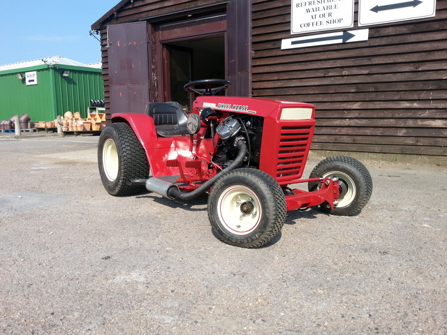
That's a nice looking machine. I think the narrow bonnet is perfectly in scale giving it a mini tractor look.
-
A great collections of machine there Kev
-
I have a Southbend Model S.. Not a big lathe by any means but it has proved so handy over the years.
In action making bearing blocks.
The finished products.
-
I bet that trike is hard to steer
Love the Wh picnic bench
Thanks for posting them up Neil
-
An interesting video Neil, thanks for posting it.. You've given me all sorts of ideas now
I wonder how long the finish lasts and how hard wearing it is..
-
-
Ahhhh.. Now I see what you were up to Koen Very good
What's it like at boiling sprouts? Fresh of course, none of that frozen stuff
-
This took some thinking about..
I think it was a Renault 11 auto with a shot trans and a very leaky full length canvas sunroof...
I swapped the engine and trans for one out of a Renault 9 with 5 speed manual box..
The leaky sunroof was ripped off and a large bit of Ford Escort roof was welded on!!
A terrible car really, I don't know why I did so much work on it!!
-
Great idea for a thread Koen,
http://youtu.be/lMT0ecEQDgY
-
Don't worry about it Mark, YT takes time to build up..
Just keep building and posting videos of your fantastic builds and your do well...
By the way, the MOM trailer has had 70 views so far which is good.. People are getting the message that MOM is out there
-
I was just thinking that ..
It's the bloke in the lead you really have to look out for
What used to be bolted to the front of the Cadet Charlie? A snowplow?
Speaking of snowplows, as well as snow I've used mine for clearing water!! It's fun creating little tidal waves
If the picture had been taken a few seconds later he would be seen him doing the "Queens wave" thing she does (or did) from her horse
-
Thanks Koen
Thanks Paul.
Thanks Rich, nope it never did go road legal... The rear tyres still said "Not for highway use"
I do need to dig my airbrush out and have a go at more custom paintwork... I'd love to do a full on 70's paint job.. Lot's of colour and lace
Thanks Tom... When I bought the Webb I had no idea it would turn into a trike a few years later. It's funny how projects can evolve
Thanks Mark... I can't remember how much it sold for other than it was the starting price despite having over 100 watchers!!
I sold it to finance a new Workshack roof.
Thanks Karl. I really should watch through some airbrush videos again to inspire me to do some more.
Thanks Matt.. Top speed was a little over 40-ish..
I would do Titch, but it's all that stops my hair blowing away
Thanks Stormin
I do have some video footage of the trike in action.. I would have to edit it as the music is not YT friendly (they banned it on my old Stig's vids channel) which would mean I would lose the engine sound as well..
Oh... I still have the original Webb seat if it's of use to anyone..
-
-
A beautiful restoration Matt, I could never restore a machine to that high standard.. Windswept and interesting is more my look
-
Only me I expect Stormin, It's how I know I'm keeping my YT lark heading in the right direction
-
I have no problems with .com
For me I only really look for .co.uk site's if I'm looking to buy something..
|
|


