

Anglo Traction
-
Content Count
1,119 -
Joined
-
Last visited
-
Days Won
143
Reputation Activity
-

 Anglo Traction got a reaction from meadowfield in Bits for my next Project
Thanks guys,
Enjoyed making the shroud and working it out as I went along. Done with that now and the engine sports a N.O.S Lodge C3 Plug-
Be a while before nexrt update, have to plan for the chassis layout etc.
-
 Anglo Traction got a reaction from Alan in Bits for my next Project
Thanks guys,
Enjoyed making the shroud and working it out as I went along. Done with that now and the engine sports a N.O.S Lodge C3 Plug-
Be a while before nexrt update, have to plan for the chassis layout etc.
-
 Anglo Traction got a reaction from Stormin in Bits for my next Project
Thanks guys,
Enjoyed making the shroud and working it out as I went along. Done with that now and the engine sports a N.O.S Lodge C3 Plug-
Be a while before nexrt update, have to plan for the chassis layout etc.
-
 Anglo Traction got a reaction from nigel in Bits for my next Project
Thanks guys,
Enjoyed making the shroud and working it out as I went along. Done with that now and the engine sports a N.O.S Lodge C3 Plug-
Be a while before nexrt update, have to plan for the chassis layout etc.
-


-
-
 Anglo Traction got a reaction from Cub Cadet in Bits for my next Project
Just about finished the copperwork on the Cowling now which should now provide more efficient removal of heat and keep the intake side cooler-
Carb side additional shroud will be riveted on, as the full shroud can be fitted and removed ok. The plate on the exhaust side will have to be detachable.
-
Anglo Traction got a reaction from Stormin in Bits for my next Project
Just about finished the copperwork on the Cowling now which should now provide more efficient removal of heat and keep the intake side cooler-
Carb side additional shroud will be riveted on, as the full shroud can be fitted and removed ok. The plate on the exhaust side will have to be detachable.
-
Anglo Traction got a reaction from nigel in Bits for my next Project
Just about finished the copperwork on the Cowling now which should now provide more efficient removal of heat and keep the intake side cooler-
Carb side additional shroud will be riveted on, as the full shroud can be fitted and removed ok. The plate on the exhaust side will have to be detachable.
-
Anglo Traction got a reaction from meadowfield in Bits for my next Project
Hi Nigel, Good to hear from you and hope all's well. Quite enjoy doing the beating of copper. Just about ready to stitch the cowl/plates together with rivets now that I've nearly sorted the Plug access hole-
Meanwhile, I had to come up with a fixing point I'd mentioned to secure the lower part of the cowl.
Decided on a split housing so that it can be easily assembled/removed. Machined 2 blocks of Duralumin to identical size, then drilled/tapped to bolt them together.
Excellent machining qualities of this metal made it a rather enjoyable job-
I was then able to machine the inner diameters to fit the flange it clamps to and clears the crank bearing and shaft by a few thousands of an inch (0.05mm).
It will also have a greased felt wiper washer inside to prevent dirt/water ingress-
This now gives me a platform to fix the cowl and hold it securely-
Have lots of swarf to clean off the machines now!.
Regards
-
Anglo Traction got a reaction from Stormin in Bits for my next Project
Hi Nigel, Good to hear from you and hope all's well. Quite enjoy doing the beating of copper. Just about ready to stitch the cowl/plates together with rivets now that I've nearly sorted the Plug access hole-
Meanwhile, I had to come up with a fixing point I'd mentioned to secure the lower part of the cowl.
Decided on a split housing so that it can be easily assembled/removed. Machined 2 blocks of Duralumin to identical size, then drilled/tapped to bolt them together.
Excellent machining qualities of this metal made it a rather enjoyable job-
I was then able to machine the inner diameters to fit the flange it clamps to and clears the crank bearing and shaft by a few thousands of an inch (0.05mm).
It will also have a greased felt wiper washer inside to prevent dirt/water ingress-
This now gives me a platform to fix the cowl and hold it securely-
Have lots of swarf to clean off the machines now!.
Regards
-
 Anglo Traction got a reaction from George Gordon in Bits for my next Project
Wasn't sure where to locate this, so as it will be 95% Metal, here's as good 'a' place as any.
Wanted to use the spare Villiers Mk2 Midget Engine I am rebuilding to power something stationary?, but will also need to have additional cooling.
I've been thinking about what I already have laying around in parts n materials I may need and started digging them out from various storage places.
Blowing the Cobwebs from my memory, I recalled back in the early 90s salvaging some parts from a 1948 Ransomes Simms & Jeffries Lawnmower, namely 2 hefty brass bearings in Plates that carry a heavy lump of (rusty) cast iron that acted as a PTO Clutch, rpm increase Gear Box and stored a lot of inertia.
The Mower itself was way past fixing up. Shame, as it had a large Starter Hand Crank, the likes of which I have never seen anywhere since. Anyway, I managed to recall where they were.
There's 2 remote Screw Capped Oilers, an old Line Shaft Bearing block (5/8" bore) with Brass Screw Down Greasers. Length of Box section Steel and 15/16" AF high Carbon Steel.
Also dug out some stubs of 1" and 5/8" AF Brass from my Garage Door Counter weights which turned out to carry several other useful bits.
Previous owner/resident of my property (60s/70s) must have been a Turner judging by the very dusty tarnished evidence-
The inside of this PTO Clutch is similar to a Diff which spins freely when drive is not engaged. A large Brake Band clamps the outer surface and the planet gears inside transfer the drive to the opposite shaft at a 5:1 increase in RPM. I plan for it to act as a speed reduction unit and PTO Clutch.
Condition inside is fairly good, considering there was water amongst the old grease.
I need to make new heavy bushings, fit new bolts and machine the outer friction face which is pitted, but still has the 'Witness' and number marks Stamped in by the guy who first assembled/finished it-
.
My main intention on this project is to refresh my limited familiarity with Lathe and metalwork practices on a fair amount of old Brass, Copper, Bronze and Steel parts. I'll be using BSF, Whitworth and BSP thread forms , and I won't be in any particular hurry to finish it, so please bear with me, as even I don't know what it is to look like yet! .
-
Anglo Traction got a reaction from Alan in Bits for my next Project
Hi Nigel, Good to hear from you and hope all's well. Quite enjoy doing the beating of copper. Just about ready to stitch the cowl/plates together with rivets now that I've nearly sorted the Plug access hole-
Meanwhile, I had to come up with a fixing point I'd mentioned to secure the lower part of the cowl.
Decided on a split housing so that it can be easily assembled/removed. Machined 2 blocks of Duralumin to identical size, then drilled/tapped to bolt them together.
Excellent machining qualities of this metal made it a rather enjoyable job-
I was then able to machine the inner diameters to fit the flange it clamps to and clears the crank bearing and shaft by a few thousands of an inch (0.05mm).
It will also have a greased felt wiper washer inside to prevent dirt/water ingress-
This now gives me a platform to fix the cowl and hold it securely-
Have lots of swarf to clean off the machines now!.
Regards
-
Anglo Traction got a reaction from nigel in Bits for my next Project
Hi Nigel, Good to hear from you and hope all's well. Quite enjoy doing the beating of copper. Just about ready to stitch the cowl/plates together with rivets now that I've nearly sorted the Plug access hole-
Meanwhile, I had to come up with a fixing point I'd mentioned to secure the lower part of the cowl.
Decided on a split housing so that it can be easily assembled/removed. Machined 2 blocks of Duralumin to identical size, then drilled/tapped to bolt them together.
Excellent machining qualities of this metal made it a rather enjoyable job-
I was then able to machine the inner diameters to fit the flange it clamps to and clears the crank bearing and shaft by a few thousands of an inch (0.05mm).
It will also have a greased felt wiper washer inside to prevent dirt/water ingress-
This now gives me a platform to fix the cowl and hold it securely-
Have lots of swarf to clean off the machines now!.
Regards
-
Anglo Traction reacted to nigel in Bits for my next Project
I used to do a bit of copper bashing using old hot water cylinders as source material, I made a few buckets and bits and bobs, it’s not as easy as it looks but once again your work is top notch 👍
-
Anglo Traction got a reaction from nigel in Bits for my next Project
Bashing copper seems to be going ok so far. Part way through doming the top to fit the cylinder head. This is to utilise the 1/4"bsf threaded hole in the top to secure it-
There will also be a fixing that uses the flange of the crankcase at the shaft bearing output side -
Fuel tank caps will be more difficult to form
-
Anglo Traction got a reaction from Stormin in Bits for my next Project
Bashing copper seems to be going ok so far. Part way through doming the top to fit the cylinder head. This is to utilise the 1/4"bsf threaded hole in the top to secure it-
There will also be a fixing that uses the flange of the crankcase at the shaft bearing output side -
Fuel tank caps will be more difficult to form
-
Anglo Traction got a reaction from Alan in Bits for my next Project
Yes Norm, very handy and will have a fair bit of work for them on this.
Not made great progress, but have machine cut/threads on several short rods and finshed the 8 brass nuts from the 1inch A/F (25.4mm) Hex stubs which are shown in the very first image on this.
Threaded 1/2" BSF and single chamfer . These represent pre-war A/F (across flats) dimension of the 9/16' Whitworth fixings-
Starting on the copper beating now the cushion is filled with sand.
Regards
-
Anglo Traction got a reaction from Stormin in Bits for my next Project
Yes Norm, very handy and will have a fair bit of work for them on this.
Not made great progress, but have machine cut/threads on several short rods and finshed the 8 brass nuts from the 1inch A/F (25.4mm) Hex stubs which are shown in the very first image on this.
Threaded 1/2" BSF and single chamfer . These represent pre-war A/F (across flats) dimension of the 9/16' Whitworth fixings-
Starting on the copper beating now the cushion is filled with sand.
Regards
-
-
Anglo Traction got a reaction from Stormin in Bits for my next Project
If you find a picture or the M.E. Magazine, would like to see it Norm. Must have been in a copy before 1984, which was when I started reading the Mag.
I'll have a go at it Ian . Have to visit a Wood Turner I know to obtain some hardwood blocks when I'm ready.
Got some Lathe time in recently. PTO work is still in progress.
Decided to change the Brake/Strap set up design and not employing a Spring Steel Strap like the Brake layout on some Garden Tractors.
Instead, I'm opting for a rigid Clam Shell type or external version of a Brake Shoe set up.
Have obtained some 6" (152.7mm) ERW Steel Tube which will cover 2 jobs. Bit of a challenge Cutting slices off with only a manual Hacksaw -
First slice in the lathe for finishing the cut end to size-
Will have 4 more of these slices to cut and they will used to make Truck Wheels, as original Cast Iron ones are rare and expensive.
The steel ring is perfect in dimension to accommodate the 3/16" thick Friction Lining and the PTO diameter-
The bearing faces of the PTO are having their faces skimmed and have been 'Spot Faced' where the Bolts pass through-
Phosphor Bronze Bearing Insert finished to outer diameter being 'Parted Off' from the Cored Billet-
Used a 1.1/2" diameter Live Centre in the Tailstock to support the work.
'Parted Off' and a light fit in the Bearing so it can be Soldered (200c) in-
Internal bore will be finished last before mounting back onto the Carrier Plate. They were retained by 1/4" Iron Rivets originally and the stress of 'Closing' the Rivets originally had cracked the Bearing flange edge at it's thinnest point. I will use specially made Countersunk Screws in reamed holes.
Have the other bearing to remove next and repeat .
-
Anglo Traction got a reaction from Cub Cadet in Bits for my next Project
Thanks Alan,
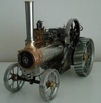
Trying to make progress while I have a reprieve from the dreaded R/Arthritis in the wrists. Just to give you an idea of this setup, here is a pic of the rough plan/layout of the working bits-
So left - right there is the water pump - speed reduction unit, then the engine. A 1954 Villiers Midget Mk2 98cc. Fully overhauled with a rebore +0.030" and new rings etc.
Being static, the engine will need additional cooling, which will require a cowling and cooling fan. The Mk3 Midget has this built in, but blows the air from the flywheel side.
I want it the other way, so have to make the shrouds , fan and drive etc.
Keeping the sort of Victorian 'Jules Verne' style, I'm using copper sheet from an old hot water cylinder for the shrouds, riveting where necessary and maybe some embelishment?
The first pattern from my drawings marked out/cut from the sheet and began rolling to the diameter of 4.5 inches (114mm approx) -
Fortunately, I have a piece of thick steel tube of the same diameter which allowed me to tightly form the intake area and rivet/solder the joint-
This is now ready for shaping (bossing) to fit the contours of the cylinder etc. A first time challenge for me.
I obtained an old Lignum Vitae Bossing Hammer in need of some considerable attention, so I refurbished it back to good condition and purchased a large 15" dia H/duty leather cushion-
Will have several jobs for these tools on this project and the washed Silver Sand is currently being dried, ready for filling the cushion.....meanwhile-
I had to redesign the engine mounting plates to position the engine inline so I can use direct couplings. I spent the last 3 days marking out, hacksawing and filing the 4 plates after drilling/reaming the holes.
Also made the reduction unit mounts ready for welding up, along with the engine ones at the same time-
With these parts all assembled in place, the shafts will line up and I can make the direct drive couplings with an allowance for any small misalignment, rather than use chains and sprockets etc.
Regards
-
Anglo Traction got a reaction from Stormin in Bits for my next Project
Thanks Alan,
Trying to make progress while I have a reprieve from the dreaded R/Arthritis in the wrists. Just to give you an idea of this setup, here is a pic of the rough plan/layout of the working bits-
So left - right there is the water pump - speed reduction unit, then the engine. A 1954 Villiers Midget Mk2 98cc. Fully overhauled with a rebore +0.030" and new rings etc.
Being static, the engine will need additional cooling, which will require a cowling and cooling fan. The Mk3 Midget has this built in, but blows the air from the flywheel side.
I want it the other way, so have to make the shrouds , fan and drive etc.
Keeping the sort of Victorian 'Jules Verne' style, I'm using copper sheet from an old hot water cylinder for the shrouds, riveting where necessary and maybe some embelishment?
The first pattern from my drawings marked out/cut from the sheet and began rolling to the diameter of 4.5 inches (114mm approx) -
Fortunately, I have a piece of thick steel tube of the same diameter which allowed me to tightly form the intake area and rivet/solder the joint-
This is now ready for shaping (bossing) to fit the contours of the cylinder etc. A first time challenge for me.
I obtained an old Lignum Vitae Bossing Hammer in need of some considerable attention, so I refurbished it back to good condition and purchased a large 15" dia H/duty leather cushion-
Will have several jobs for these tools on this project and the washed Silver Sand is currently being dried, ready for filling the cushion.....meanwhile-
I had to redesign the engine mounting plates to position the engine inline so I can use direct couplings. I spent the last 3 days marking out, hacksawing and filing the 4 plates after drilling/reaming the holes.
Also made the reduction unit mounts ready for welding up, along with the engine ones at the same time-
With these parts all assembled in place, the shafts will line up and I can make the direct drive couplings with an allowance for any small misalignment, rather than use chains and sprockets etc.
Regards
-
Anglo Traction got a reaction from meadowfield in Bits for my next Project
Thanks Alan,
Trying to make progress while I have a reprieve from the dreaded R/Arthritis in the wrists. Just to give you an idea of this setup, here is a pic of the rough plan/layout of the working bits-
So left - right there is the water pump - speed reduction unit, then the engine. A 1954 Villiers Midget Mk2 98cc. Fully overhauled with a rebore +0.030" and new rings etc.
Being static, the engine will need additional cooling, which will require a cowling and cooling fan. The Mk3 Midget has this built in, but blows the air from the flywheel side.
I want it the other way, so have to make the shrouds , fan and drive etc.
Keeping the sort of Victorian 'Jules Verne' style, I'm using copper sheet from an old hot water cylinder for the shrouds, riveting where necessary and maybe some embelishment?
The first pattern from my drawings marked out/cut from the sheet and began rolling to the diameter of 4.5 inches (114mm approx) -
Fortunately, I have a piece of thick steel tube of the same diameter which allowed me to tightly form the intake area and rivet/solder the joint-
This is now ready for shaping (bossing) to fit the contours of the cylinder etc. A first time challenge for me.
I obtained an old Lignum Vitae Bossing Hammer in need of some considerable attention, so I refurbished it back to good condition and purchased a large 15" dia H/duty leather cushion-
Will have several jobs for these tools on this project and the washed Silver Sand is currently being dried, ready for filling the cushion.....meanwhile-
I had to redesign the engine mounting plates to position the engine inline so I can use direct couplings. I spent the last 3 days marking out, hacksawing and filing the 4 plates after drilling/reaming the holes.
Also made the reduction unit mounts ready for welding up, along with the engine ones at the same time-
With these parts all assembled in place, the shafts will line up and I can make the direct drive couplings with an allowance for any small misalignment, rather than use chains and sprockets etc.
Regards