

Anglo Traction
-
Content Count
1,119 -
Joined
-
Last visited
-
Days Won
143
Reputation Activity
-

 Anglo Traction got a reaction from Cub Cadet in Bits for my next Project
Thanks, hope all's well Ewan. A large void on here now without Norm
Reached a point where there's lots of jobs that don't immediately produce finished parts. Lots of 'jigging' mounts that locate exactly where I want them prior to welding up.
Managed to prime the chassis frame and black paint the underside. More holes to drill yet, so left it at that stage.
Turned to fuel tanks and the mounting thereof. Lots of hammering/annealing of copper to form the bullet shape to fit onto the shell cartridge.
Started with a section of tube 1.1/2" (38mm) in diameter and wall thickness of 1/16" (1.6mm) shown in the bottom centre of the pic.
The one I'm working on is the main tank, having a screw on filler cap and looking a bit like a flask-
I have to make another former of some kind to finish to the shape I need in order to make 2 of them, one main tank and one reserve.
The reserve tank will be inverted for design purposes and will become obvious when assembled (I hope).
Regards
-
 Anglo Traction got a reaction from nigel in Bits for my next Project
Well done sir!. Look's like you have enough there to produce some good projects. The Myford254 is a good machine. Regards. Richard
-
 Anglo Traction reacted to nigel in Bits for my next Project
Got some new toys for my workshop today Richard
-
 Anglo Traction got a reaction from Alan in Bits for my next Project
Thanks, hope all's well Ewan. A large void on here now without Norm
Reached a point where there's lots of jobs that don't immediately produce finished parts. Lots of 'jigging' mounts that locate exactly where I want them prior to welding up.
Managed to prime the chassis frame and black paint the underside. More holes to drill yet, so left it at that stage.
Turned to fuel tanks and the mounting thereof. Lots of hammering/annealing of copper to form the bullet shape to fit onto the shell cartridge.
Started with a section of tube 1.1/2" (38mm) in diameter and wall thickness of 1/16" (1.6mm) shown in the bottom centre of the pic.
The one I'm working on is the main tank, having a screw on filler cap and looking a bit like a flask-
I have to make another former of some kind to finish to the shape I need in order to make 2 of them, one main tank and one reserve.
The reserve tank will be inverted for design purposes and will become obvious when assembled (I hope).
Regards
-

-
Anglo Traction got a reaction from Cub Cadet in Bits for my next Project
Thanks Gents, Yes Norm, I'm also beginning to enthuse about it's completion.
Advancement of only a small part of the project, but is of significance to my ability to produce it. I've just about finished the front Caster wheel assembly-
It's taken me a while now to produce and assemble all the parts. Final job was putting a chamfer on the wheel rims-
One step closer to havng a rolling chassis, so I'll put this to one side.
Only the barest perceptible wobble, which I'll try to eliminate, (but not too hard) before having the spokes professionally welded to the rim.
Regards.
-
Anglo Traction got a reaction from Cub Cadet in Bits for my next Project
Thank you Gents!. Still learning as I go and making reasonable progress. Finished the parts for the front caster assembled here with a temporary bolt, so just the wheel to make-
I had to make the 1/2" BSF Pin Bolt to ensure a good fit and with fine adjustment. I have some 15/16" AF high carbon Hex steel, so set to and turned one up on the lathe-
Also made a nut.
I bit the bullet and started 'tacking' the frame joints and managed to continue with reasonble weld joints to form a strong frame. I wll need to get the upper surface joints properly done.
The mahogany planks have been cut and temporarily fitted for trimming to bring the surface level with the frame's surface. Embelishments include a brass nut cover to keep it weather tight-
.........and we all like to 'trial assemble', so this gives a better image of the project-
Regards
-
Anglo Traction got a reaction from Cub Cadet in Bits for my next Project
Bit of progress on making parts, turned up a few bronze pieces for a change, starting with a pair of captive chassis axle to wheel thrust bearings. Shaft size is 9/16" (>13mm) dia-
Then drew up the front Caster wheel design, sourced some rectangular thick box section steel and started on the axial bearing.
Took a slice of bronze off the 2" dia hollow bar after boring out to exactly 1" (25.4mm) first-
I planned to use 5/32" bearing balls from old bearing stock like I did with the Drill Project a few years back. Calculated the number required (18) and set up for machining on the rotary table.
As I was slot drilling through the cage plate, i had to use thin birch ply under it. Using a 'Ball Nosed Slot Drill' of the same diameter as the balls, they sit very comfortably in the respective positions-
I then machined a shallow 'race' in the 2 mating bearing plates using the same table settings, leaving running clearance on each side of the cage plate-
Very pleased with the way this bit went, being my first attempt at an Axial Bearing and it all runs very smoothly (without grease) when assembled.
Regards
-
Anglo Traction got a reaction from Cub Cadet in Bits for my next Project
Reduction gear clutch parts finished now and all fit nicely in the finished bearing plates. Painted a nice shiney black enamel, it goes well with the polished brass parts-
Couple of jobs to do before I fit the innards to the Reduction unit, but able to move on to couplings and chassis design.
Regards
-
Anglo Traction got a reaction from Cub Cadet in Bits for my next Project
This part is very nearly ready for welding up and riveting now I've finished making the copper rivets and shaping the friction linings. Gives me 19.5 sq ins(126sq cms) of contact, so plenty of grip.
The bar with the springs will serve to keep the "Shoes' open and apply equal pressure when shoes are closed onto the PTO by 'over centre' lever lock and cable operation-
Regards
-
Anglo Traction got a reaction from Cub Cadet in Bits for my next Project
Just about finished the copperwork on the Cowling now which should now provide more efficient removal of heat and keep the intake side cooler-
Carb side additional shroud will be riveted on, as the full shroud can be fitted and removed ok. The plate on the exhaust side will have to be detachable.
-
Anglo Traction got a reaction from Cub Cadet in Bits for my next Project
Thanks Alan,
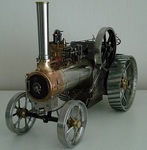
Trying to make progress while I have a reprieve from the dreaded R/Arthritis in the wrists. Just to give you an idea of this setup, here is a pic of the rough plan/layout of the working bits-
So left - right there is the water pump - speed reduction unit, then the engine. A 1954 Villiers Midget Mk2 98cc. Fully overhauled with a rebore +0.030" and new rings etc.
Being static, the engine will need additional cooling, which will require a cowling and cooling fan. The Mk3 Midget has this built in, but blows the air from the flywheel side.
I want it the other way, so have to make the shrouds , fan and drive etc.
Keeping the sort of Victorian 'Jules Verne' style, I'm using copper sheet from an old hot water cylinder for the shrouds, riveting where necessary and maybe some embelishment?
The first pattern from my drawings marked out/cut from the sheet and began rolling to the diameter of 4.5 inches (114mm approx) -
Fortunately, I have a piece of thick steel tube of the same diameter which allowed me to tightly form the intake area and rivet/solder the joint-
This is now ready for shaping (bossing) to fit the contours of the cylinder etc. A first time challenge for me.
I obtained an old Lignum Vitae Bossing Hammer in need of some considerable attention, so I refurbished it back to good condition and purchased a large 15" dia H/duty leather cushion-
Will have several jobs for these tools on this project and the washed Silver Sand is currently being dried, ready for filling the cushion.....meanwhile-
I had to redesign the engine mounting plates to position the engine inline so I can use direct couplings. I spent the last 3 days marking out, hacksawing and filing the 4 plates after drilling/reaming the holes.
Also made the reduction unit mounts ready for welding up, along with the engine ones at the same time-
With these parts all assembled in place, the shafts will line up and I can make the direct drive couplings with an allowance for any small misalignment, rather than use chains and sprockets etc.
Regards
-
Anglo Traction got a reaction from Cub Cadet in Bits for my next Project
Drawn up engine mounting plate design and need to obtain steel sheet to make 4.
The 2 stanchions from 60 x 40 mild steel box are taking shape ready for welding up -
Had been searching for a genuine Villiers vintage exhaust, but realised they want too much money for not much style. I decided to make my own to suit the design I wanted
An empty disposable propane cylinder became the victim after getting the picture in my mind of how I want it. Constituent parts after much searching of materials, measuring, cutting & machining-
Ready to weld the 3 tubes for the outlet to the body and the test fit of the brass banding which seals and registers the butt joint end cap prior to riveting up-
The brass banding was cut from sheet, rolled and silver soldered the ends to form a close fitting ring.
The brass outlet pipe is from a 1954 mower front wooden roller insert, and the fishtail outlet is from a redundant 1960s Ronson Blow torch kit.
All finished and a coat of VHT paint cooked at Gas Mk6 for an hour-
I've got a finned exhaust clamp from a Triumph T120 which fits perfectly to fix it onto the engine.
Regards.
-

 Anglo Traction got a reaction from ranger in Stormin
So sorry to hear of his sudden passing. My thoughts also are with the family.
The loss of a good, 'down-to-earth' person will be much missed, and also on this, and the Redsquare Forum.
R.I.P. Norm, we won't forget you.
Richard
-
Anglo Traction reacted to Prof in Stormin
Hi All, sorry to be the bearer of bad news but Stormin Norman Dainton died from a stroke last week. Sounds like it was sudden
I knew him from the Land Rover community but know he was on here fairly often.
This was him and Carol on 4th August this year when he visited us in Mid Wales. My wife tried to poison him with spicy foreign muck (Spaghetti Bolognese), he'd never had spaghetti before.
A true gentleman with a dry northern wit and will be sorely missed by all that knew him.
Chris
-
 Anglo Traction got a reaction from Stormin in Bits for my next Project
Thanks Gents, Yes Norm, I'm also beginning to enthuse about it's completion.
Advancement of only a small part of the project, but is of significance to my ability to produce it. I've just about finished the front Caster wheel assembly-
It's taken me a while now to produce and assemble all the parts. Final job was putting a chamfer on the wheel rims-
One step closer to havng a rolling chassis, so I'll put this to one side.
Only the barest perceptible wobble, which I'll try to eliminate, (but not too hard) before having the spokes professionally welded to the rim.
Regards.
-
Anglo Traction got a reaction from nigel in Bits for my next Project
Thanks Gents, Yes Norm, I'm also beginning to enthuse about it's completion.
Advancement of only a small part of the project, but is of significance to my ability to produce it. I've just about finished the front Caster wheel assembly-
It's taken me a while now to produce and assemble all the parts. Final job was putting a chamfer on the wheel rims-
One step closer to havng a rolling chassis, so I'll put this to one side.
Only the barest perceptible wobble, which I'll try to eliminate, (but not too hard) before having the spokes professionally welded to the rim.
Regards.
-
Anglo Traction got a reaction from Cub Cadet in Bits for my next Project
Had some lathe and milling machine time in recently. Started on the wheel for the front caster. Had barely enough 40mm dia EN8 Steel to make the hub and leave enough for the drive coupling.
Had to work really close to the chuck jaws, which was going fine with light feed, then I noticed the 'in-feed' movement of the parting tool went 'light' and easier !. I withdrew the tool and found it had failed !.
As I bought it in a modestly priced set 38 years ago and just lightly stoned the cutting edge now and again, it has served me very well-
I finished off with a narrow HSS type with no issues.
Indexed and drilled for the spokes on the Mill with barely 1.5mm clearance between rotary table wheel and chuck ! -
Also added an angled grease point and made the bronze bushes to be pressed in later-
I decided to keep the original engine output drive clutch bell and make a driven plate to replace the original Mower Clutch plates to form a coupling.
This would allow for any tiny misalignment of the engine and the reducton unit.
The load transfered through this part will be much less than it was orignally handling in a Mower, but I wanted it to be efficient and reliable.
Ordered a 105mm x 4mm laser cut mild Steel disc and meanwhile, I made 6 bronze wear pads -
The slitting saw used is only 0.0125" (0.3mm) thick. These pads were soldered to the dog spokes of the plate where they will contact the recesses in the clutch bell.
The plate was then set up to drill the 6 HT fixing screws to the boss-
Once I had cut the keyway in the boss, I pressed the plate with the drilled and countersunk holes onto the boss and finished fitting the screws. i need to file out the keyway in the plate to depth.
The bell drive recesses needed weld metal added where they were worn from mowing since 1954, but were not bad at all -
The caster wheel is at the final assembly stage. My reasons for using surplus thick walled steel tubing for the rim left over from my previous Water Cart wheel making becomes clear.
It all fits and allows me to re-use the wheel jig for accurate assembly ! -
Regards
-
Anglo Traction got a reaction from Stormin in Bits for my next Project
Had some lathe and milling machine time in recently. Started on the wheel for the front caster. Had barely enough 40mm dia EN8 Steel to make the hub and leave enough for the drive coupling.
Had to work really close to the chuck jaws, which was going fine with light feed, then I noticed the 'in-feed' movement of the parting tool went 'light' and easier !. I withdrew the tool and found it had failed !.
As I bought it in a modestly priced set 38 years ago and just lightly stoned the cutting edge now and again, it has served me very well-
I finished off with a narrow HSS type with no issues.
Indexed and drilled for the spokes on the Mill with barely 1.5mm clearance between rotary table wheel and chuck ! -
Also added an angled grease point and made the bronze bushes to be pressed in later-
I decided to keep the original engine output drive clutch bell and make a driven plate to replace the original Mower Clutch plates to form a coupling.
This would allow for any tiny misalignment of the engine and the reducton unit.
The load transfered through this part will be much less than it was orignally handling in a Mower, but I wanted it to be efficient and reliable.
Ordered a 105mm x 4mm laser cut mild Steel disc and meanwhile, I made 6 bronze wear pads -
The slitting saw used is only 0.0125" (0.3mm) thick. These pads were soldered to the dog spokes of the plate where they will contact the recesses in the clutch bell.
The plate was then set up to drill the 6 HT fixing screws to the boss-
Once I had cut the keyway in the boss, I pressed the plate with the drilled and countersunk holes onto the boss and finished fitting the screws. i need to file out the keyway in the plate to depth.
The bell drive recesses needed weld metal added where they were worn from mowing since 1954, but were not bad at all -
The caster wheel is at the final assembly stage. My reasons for using surplus thick walled steel tubing for the rim left over from my previous Water Cart wheel making becomes clear.
It all fits and allows me to re-use the wheel jig for accurate assembly ! -
Regards
-
Anglo Traction got a reaction from Alan in Bits for my next Project
Had some lathe and milling machine time in recently. Started on the wheel for the front caster. Had barely enough 40mm dia EN8 Steel to make the hub and leave enough for the drive coupling.
Had to work really close to the chuck jaws, which was going fine with light feed, then I noticed the 'in-feed' movement of the parting tool went 'light' and easier !. I withdrew the tool and found it had failed !.
As I bought it in a modestly priced set 38 years ago and just lightly stoned the cutting edge now and again, it has served me very well-
I finished off with a narrow HSS type with no issues.
Indexed and drilled for the spokes on the Mill with barely 1.5mm clearance between rotary table wheel and chuck ! -
Also added an angled grease point and made the bronze bushes to be pressed in later-
I decided to keep the original engine output drive clutch bell and make a driven plate to replace the original Mower Clutch plates to form a coupling.
This would allow for any tiny misalignment of the engine and the reducton unit.
The load transfered through this part will be much less than it was orignally handling in a Mower, but I wanted it to be efficient and reliable.
Ordered a 105mm x 4mm laser cut mild Steel disc and meanwhile, I made 6 bronze wear pads -
The slitting saw used is only 0.0125" (0.3mm) thick. These pads were soldered to the dog spokes of the plate where they will contact the recesses in the clutch bell.
The plate was then set up to drill the 6 HT fixing screws to the boss-
Once I had cut the keyway in the boss, I pressed the plate with the drilled and countersunk holes onto the boss and finished fitting the screws. i need to file out the keyway in the plate to depth.
The bell drive recesses needed weld metal added where they were worn from mowing since 1954, but were not bad at all -
The caster wheel is at the final assembly stage. My reasons for using surplus thick walled steel tubing for the rim left over from my previous Water Cart wheel making becomes clear.
It all fits and allows me to re-use the wheel jig for accurate assembly ! -
Regards
-
Anglo Traction got a reaction from nigel in Bits for my next Project
Thank you Gents!. Still learning as I go and making reasonable progress. Finished the parts for the front caster assembled here with a temporary bolt, so just the wheel to make-
I had to make the 1/2" BSF Pin Bolt to ensure a good fit and with fine adjustment. I have some 15/16" AF high carbon Hex steel, so set to and turned one up on the lathe-
Also made a nut.
I bit the bullet and started 'tacking' the frame joints and managed to continue with reasonble weld joints to form a strong frame. I wll need to get the upper surface joints properly done.
The mahogany planks have been cut and temporarily fitted for trimming to bring the surface level with the frame's surface. Embelishments include a brass nut cover to keep it weather tight-
.........and we all like to 'trial assemble', so this gives a better image of the project-
Regards
-
Anglo Traction got a reaction from Alan in Bits for my next Project
Thank you Gents!. Still learning as I go and making reasonable progress. Finished the parts for the front caster assembled here with a temporary bolt, so just the wheel to make-
I had to make the 1/2" BSF Pin Bolt to ensure a good fit and with fine adjustment. I have some 15/16" AF high carbon Hex steel, so set to and turned one up on the lathe-
Also made a nut.
I bit the bullet and started 'tacking' the frame joints and managed to continue with reasonble weld joints to form a strong frame. I wll need to get the upper surface joints properly done.
The mahogany planks have been cut and temporarily fitted for trimming to bring the surface level with the frame's surface. Embelishments include a brass nut cover to keep it weather tight-
.........and we all like to 'trial assemble', so this gives a better image of the project-
Regards
-
Anglo Traction got a reaction from Stormin in Bits for my next Project
Thank you Gents!. Still learning as I go and making reasonable progress. Finished the parts for the front caster assembled here with a temporary bolt, so just the wheel to make-
I had to make the 1/2" BSF Pin Bolt to ensure a good fit and with fine adjustment. I have some 15/16" AF high carbon Hex steel, so set to and turned one up on the lathe-
Also made a nut.
I bit the bullet and started 'tacking' the frame joints and managed to continue with reasonble weld joints to form a strong frame. I wll need to get the upper surface joints properly done.
The mahogany planks have been cut and temporarily fitted for trimming to bring the surface level with the frame's surface. Embelishments include a brass nut cover to keep it weather tight-
.........and we all like to 'trial assemble', so this gives a better image of the project-
Regards
-
 Anglo Traction got a reaction from Mike in NC in Let's see some Briggs Collections
Hi Mike, Good collection and restoration work I presume on your behalf. A fellow Countryman of yours who left the Forum several years ago, also was a Briggs collector.
His name was Matt, but left us many images. Here is a link to just one of his contribrutions, but if you scan for his others on pages 4 & 5 also of this section, you'll find many-
Briggs
Regards
-
Anglo Traction got a reaction from Stormin in Bits for my next Project
Bit of progress on making parts, turned up a few bronze pieces for a change, starting with a pair of captive chassis axle to wheel thrust bearings. Shaft size is 9/16" (>13mm) dia-
Then drew up the front Caster wheel design, sourced some rectangular thick box section steel and started on the axial bearing.
Took a slice of bronze off the 2" dia hollow bar after boring out to exactly 1" (25.4mm) first-
I planned to use 5/32" bearing balls from old bearing stock like I did with the Drill Project a few years back. Calculated the number required (18) and set up for machining on the rotary table.
As I was slot drilling through the cage plate, i had to use thin birch ply under it. Using a 'Ball Nosed Slot Drill' of the same diameter as the balls, they sit very comfortably in the respective positions-
I then machined a shallow 'race' in the 2 mating bearing plates using the same table settings, leaving running clearance on each side of the cage plate-
Very pleased with the way this bit went, being my first attempt at an Axial Bearing and it all runs very smoothly (without grease) when assembled.
Regards