| |
-
Slow progress lately. Have been pondering over the tank mounting design, but reckon I've found the answer.
The cooling fan assembly is now finished and the brass support plates nearly finished-
Just finished welding up the Reduction Gear mounting, so can start on prep for painting. Still working on Reserve tank hammering copper before I can finalise the mountings.
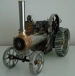
Fuel tank support mounts shown in this image-
Hopefully won't be too long before next update.
Regards
-
Hello John,
Sorry for the slow response.
The spindle is in 2 pieces, the lower length 7. 1/2" (190mm) x 3/4" dia (19.05mm).
The upper section 7. 5/8" ( 193mm) and is 3/8" dia. this upper piece is press fitted into the lower section and pinned with a 1/8" dia dowel.
So it would need to be longer to account for the fit overlap if you're making one.
The milled keyway, as mentioned was reduced to about 3. 1/2" (89mm) to allow for increased bearing surface in the lower bearing (body casting).
The thrust bearing has 2 sections of 1'" dia (25.4mm) x 3/16" (4.75mm) with races machined in both to accommodate 5/32" ball bearings, then hardened/tempered
I believe the original chucks were knurled for hand tightening, but mine had been changed/bodged.
The colour was made up/matched by myself using good quality enamels.
Hope this helps.
Regards
-
One of those red wires (likely the sleeved one) is possibly the coil earth IF the coil winding wrap is insulated from the soft iron laminated coil plate?.
If so, then the other red wire is from the coil's primary winding and services the breaker points.
The issue with the image references is the 3rd image that shows the COM lead point contacting the insulated half of the breaker point which is open, But you don't show or say where the Red 'V' lead point is contacting!.
I see that the smaller red wire is (presumably) spliced into the (black) condenser wire.
You should isolate the condenser from that lead if you want to test the resistance of the primary winding, which if ok will give you a resistance reading of approx 2 to 2.5. I don't have the actual value.
That test should be:- Red point on the wire from the primary winding and the black COM point to an earth point.
Keep at it. I presume the magnet(s) in the flywheel are still strong enough to produce a spark?.
It's many years since i messed with one of these, I can't remember if the flywheel is 'Keyed" for fixed timing, or requires setting up. Wristpin is the man you need. Hopefully he will look in.
Regards
-
Hello David, Welcome. Hopefully you will have success in your research of Conyers. I have seen several products with their name from the 60s>.
Your engine is a Briggs and Stratton, possibly 3hp , or even 4hp. You can obtain all the parts lists and opersting manuals based on the Model, Spec and Serial numbers stamped into the engine cowling right next to the Governor adjusting screw/Rod behind the Air Filter in your posted image.
I refurbished a '72' Genset some years back with the same engine and it's progress was logged in this section of the forum. If it is of any help, here is a link- 72 Genset
If you need any help with the engine, just post it here. Afraid I can't help with the generating part, as I'm not familiar with it.
Regards.
-
Finished making the (12) 6BA Bronze bolts and brass nuts for the Fan Shaft bearing/grease point housings over the last weekend and now trial assembled on the unit. All good-
-
Many thanks for the comments. Sorry for being quiet for a while. Have been busy when able. Lots of decision making on design and machine time, but seem to produce little visually.
The Tank Cartridges were set up for drilling and tapping. Had to obtain a metre of 10mm studding to make the fixings, as they're quite tall-
Luckily the igniter percussion inserts drilled out ok, then tapped both bases 1/8"BSP for the fittings.
The fuel taps were done as per previous post, so then just the Air Valve to design and make. Shown in next image on the left-
The left one shows the top of the reserve tank and the right shows the base of the main tank.
Next job was the fan shaft layout, bearing housings and 'Screw Down Grease Cups'. I had the latter vintage cups, but had to make the housings for them out of cast bronze bar.
Made a lot of work for myself milling to shape just to form the platforms to screw the cups into-
Finished them on the lathe so that I could fit a short piece of brass tube between them as a seal against water ingress-
Cheated a bit with these, as I'm hard soldering them to large flat brass washers to make the flange for bolting through and will match (in size, not colour) the ball bearing housings also machined from solid-
So here is the basic assembly/layout of the fan shaft and now about to start on the sprocket mount and fan/blades-
Regards
-
Finished the Fuel Taps. Lots of different set-ups and operations required. Did much of the work while still part of the parent brass rod. Cross drilling 3/8"(9.55mm)-
I wanted the tap levers opposed to eachother for access (in the off position), so had to be careful when it came to drilling through with the tapered plugs fitted-
.
The Tap's cam limit plates had to be soldered together, then to a stub of brass for machining to shape using a rotary table-
When as much work as possible was done, I cut them away from the parent bar and 'Silver Soldered' the pipe connection rods to the Tap bodies.
All the fiitings are for 3/16" (4.75mm) copper pipe. The tap tapers are 'pulled in' using the correct 'Thackery' coil spring washers and provides just the right amount of resistance-
A light polish and just need proper 1/16" Split (cotter) Pins to finish off. Maybe blend the joints. Happy with this first time job for me.
Regards
-
Not a lot of progress, what with the cold spell of the last 3 weeks. Confined myself in the warmer environment of the Lounge. Too cold in the workshop.
Have been designing and drawing up the Fuel fittings I require. Nothing 'off the shelf' will suit, so making my own and using a 1950s ATCO Pet Cock as a guide (shown on the right).
Got some Lathe time in over last few days and started turning up a Taper Reamer blank, then a first Pet Cock plug at the same settings. Got to produce several of these so I have a stock.
The taper angle is 7 degrees inclusive . The little levers that screw into the plug are threaded 5/32" Whitworth, so making them the same -
Had to keep to Imperial, not easy to mix metric on these, plus I have been asked to reproduce an old Pet Cock style for a restoration.
Ready to part off the finished plug from the rod and make the next one now.
The reamer blank is next to finish machining the cutting edges, then harden, temper and hone.
Quite pleased really, as the new plug actually fits perfectly in the old tap body, so I got the angle right.
Regards.
-
Thank you Gents for your positive comments. Lot of work sorting the Reduction Unit design set up.
I needed to provide stanchions for the tank(s) support and location, bearing support for the fan drive, Pto clutch lever mount point and lubricator positions, all in one area.
I decided on brass plates for extending up to fan shaft line. Started with an old 12 inch (305mm) square plate shown during marking out-
After lot of cutting and careful drilling time, I was able to fit it and began the stiffening with bracing layout and fittng the welded and shaped stanchions.
Lubrication connections made to fit into the large brass bearings, then made/fitted the mountings for the Lubricators.
These Lubricators were found in an old barn about 15 years ago and are shown in the very first image of this Topic. Had to anneal the thick walled copper pipes, shaped to fit using a home made tube bender also shown in the image below-
Had to use incompatible metals in this unit (electrolytic/galvanic reaction risk), so will have to be careful to seal the mating surfaces of the Aluminium and Brass parts, even though they will be polished and lacquered.
Hoping to get this unit''s mounting plate/support welded up soon.
Regards and wishing all a Happy New Year
-
Only just spotted this post. Assuming you are in the UK?, have you tried the Stationary Engine Forum?. Obviously you will to register, but there is a good chance someone on there could help you.
Here is a -LINK-
-
Had an opportunity to obtain this Sprayer in exchange for a contribution to a Charity.
It was in a sad state after being exposed to sun light and temperature extremes for many years.
The all important nozzle was missing, a large dent in the base and the wooden handles were very dry and cracked with shrinkage.
Solid Brass and riveted/soldered joints, the item weighs 2.060 kgs dry.
Fortunately, the Museum Curator had another near complete example, so I was able to borrow the nozzle parts for reproduction.
Found the thread form was 1/8" BSP parallel, but several thousanths of an inch under size!.
The main nozzle part wasn't difficult to produce, but had to make a reamer to form the minute taper of the outlet and produced the atomiser/restricter which was complicated-
The Air Pump leather washer was tired and still fairly good, but made a new one from slightly thicker raw leather -
Thie plunger is obviously tighter, but needs to relax and bed in and is easing with use. Being a pressure vessel, the control tap and pressure relief valve are all clean a working well-
The hardwood plunger handle was so dry, it soaked up 20ml of raw linseed oil on the first feed. Another 5ml satified it's thirst and the cracks slowly closed up over a week.
All back together and waiting for an acid, then soap, then soda washout, the latter to neutralise the ph level to 7.-
Ignore the extra 'Thumb Nut' on the back of the horizontal handle, it is one I made for the museum example that was missing it. Bit of ageing and it will merge in well.
My example may well be a 'Suds Pump' cutting oil feed for my Myford to save on electricity. So, a very nice piece of early 1950s quality re purposed.
Regards
-
I've been designing/making several parts over the last month. decided to go for rope pull start on the engine, simpler job and I could use an old pulley that was used originally on the 'Yellow Mower Challenge ATCO' back in around 1959. The pulley is a 4" Picador with angled slots cut in and filed for the rope knotted end. I had to make the brass retaining bolt once I'd identified the flywheel nut thread form (9/16" x 20tpi BSC). It is fairly quick to remove to gain access to the ignition points/mag-
The mahogany bumper blocks were added so as to allow a short overhang of the pulley/flywheel and puts the engine/mount centre line over the rear axle.
The finished engine mount has some embelishments added in the form of brass straps-
Working on the fuel tanks stand/mount presently and have finished bashing the copper to shape for the top of the main fuel tank.
In the end, I used a highly polished 'Tow Bar' Ball unit as a 'Dolly' to form the copper shape -
I have more work to do on it before soldering up and make the reserve tank.
Reduction gear mounts next and the drive etc for the cooling fan.
Regards
-
Well done sir!. Look's like you have enough there to produce some good projects. The Myford254 is a good machine. Regards. Richard
-
Thanks, hope all's well Ewan. A large void on here now without Norm
Reached a point where there's lots of jobs that don't immediately produce finished parts. Lots of 'jigging' mounts that locate exactly where I want them prior to welding up.
Managed to prime the chassis frame and black paint the underside. More holes to drill yet, so left it at that stage.
Turned to fuel tanks and the mounting thereof. Lots of hammering/annealing of copper to form the bullet shape to fit onto the shell cartridge.
Started with a section of tube 1.1/2" (38mm) in diameter and wall thickness of 1/16" (1.6mm) shown in the bottom centre of the pic.
The one I'm working on is the main tank, having a screw on filler cap and looking a bit like a flask-
I have to make another former of some kind to finish to the shape I need in order to make 2 of them, one main tank and one reserve.
The reserve tank will be inverted for design purposes and will become obvious when assembled (I hope).
Regards
-
So sorry to hear of his sudden passing. My thoughts also are with the family.
The loss of a good, 'down-to-earth' person will be much missed, and also on this, and the Redsquare Forum.
R.I.P. Norm, we won't forget you.
Richard
-
Hi Ray,
Ah, Ok. That is Municipal/Commercial grade machinery which is way outside my parameters of familiarisation. Can't find any positive responses from a search of the Model number AG2327.
SPS tractors website are out of stock.
So if it's a Briggs, you should know where you are with that. Good to hear how you get on with it.
Regards
-
Hi Ray,
If it's one of the Wolseley Merry Tiller Models with a Scythe attachment, you will need to obtain a Manual for the Machine you wish to refer to and one for the Scythe attachment.
Found loads online. here is an example for the 36" Scythe
Is this a new project?
Regards,
Richard.
-
Bonjour Noel,
Veuillez trouver un lien vers l’annonce eBay.
Landmaster L150
Regards.
-
Bonjour, Veuillez vérifier ici dans quelques jours. Je pourrai peut-être vous aider.
Cordialement. Richard.
(hello, please check here in a few days. I may be able to help)
-
Thanks Gents, Yes Norm, I'm also beginning to enthuse about it's completion.
Advancement of only a small part of the project, but is of significance to my ability to produce it. I've just about finished the front Caster wheel assembly-
It's taken me a while now to produce and assemble all the parts. Final job was putting a chamfer on the wheel rims-
One step closer to havng a rolling chassis, so I'll put this to one side.
Only the barest perceptible wobble, which I'll try to eliminate, (but not too hard) before having the spokes professionally welded to the rim.
Regards.
-
If you still have the WH wheel bolts handy Ray, I will check with Roly to see if he still needs them and will drop you a PM. Thanks very much for that.
Regards
-
Just for everyone's information. I have uploaded the available manual in PDF form for the Hayter Osprey and 21 machines. It's in the orange header line marked DOWNLOADS. Engine data will need to be obtained from the B&S website.
Regards
-
Just for everyone's information. I have uploaded the available manual in PDF form for the Hayter Osprey and 21 machines. It's in the orange header line marked DOWNLOADS. Engine data will need to be obtained from the B&S website.
Regards
-
Version 1.0.0
54 downloads
User and Parts Manual for both machines. Page format will need to re orientated to view.
-
Hi Ray, Hope all's well. You beat me to it.
JonW- I have replied to your PM.
Regards
|
|