| |
-
Good machine and well done for wanting to bring it back to life. All the help you'll ever need for it is on here with the O&R enthusiasts.
I'm sure you're wise to it, but being a U.S machine, the Fuel ratio needs to be aligned with UK Fl oz and Gallon measures to produce the correct ratio.
good luck. May be interested in knowing which Manuals you have.
I volunteer for a Gardening Museum in Sussex, and we have many Mowers etc, some we may require detail for.
Regards.
-
There is a comprehensive topic on Hayter Osprey in the 'Other Garden Machines'. Link proved here-
Also, look at the Home Page again and look down on the righthand side column to find 'Files'. At the bottom I've located a downloadable copy of the User Manual.
See how you get on.
-
Hello Martin, Only just found your post. Sorry, I'm too far away to help. I may however be able to help with a 6 speed transmission if yours is not repairable. Hope you get it sorted.
-
Hello Tony,
Only just seen your post. Afraid the dimensions you state don't relate to my faded memory of the chain size.
I thought it was a 1/2" pitch (12.7mm)?, but could be 5/8" (15.9mm). The best thing you an do is match yours to a chart and order one.
Here is a good chart example by a long established British company. Note:- 1970s machines would have use imperial sizes. Modern chains still use the dimensions, but in metric also. Pin size is very important and needs measuring accurately to ensure a good fit. Chain Chart
-
With all the hose clamps finished, they were checked for tightness and then several coats of Rylard Incralac Lacquer for protection-
Settled for a quick way to resolve the prevention of water (rain) ingress. Soldered a plated brass hood to the original Air intake filter body-
-
Thank you for the compliments sir!. Much appreciated, My own worst enemy as far as detail and concept is concerned. Hope you are still enjoying the rewards of your Triumph Gloria.
Had to compromise with the last hose clamp for the outlet end. Used 1/16" copper plate for it and had some 5/16" copper rod left over from rivet making for the toggles:-
All these bits will be coated with Rylard Incralac Lacquer. Carb intake hood and a Spark Plug cover to make next.
-
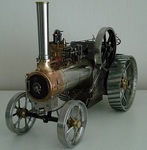
Getting close to finishing this. Here's a few images of this project -
-
Have been laid up for 2 weeks with a pretty severe virus that's been going around. Nearly back to normal and have been trying to catch up on a few jobs.
Having now acquired decent hose for 1 inch fittings, I drew up the wide hose clamp design and searched my stock for brass. Had enough for three clamps- Pickup end, pump inlet and outlet. the delivery outlet will need some thought. Plates cut and drilled:-
Had some hard thinking about how to form them, but sorted it:-
Found some 5/16" dia brass for the toggles in my brass scrap box (float arm from a cistern valve). Finished these now, but need more brass 3/16" whitworth screws:-
A need for a towing handle was satisfied by salvaging a crank handle from an old Conservatory roof light.
Had to dismantle and reshape it to my needs and make a new wooden handle grip, but all brass fits well with the project 36" in length (92cms):-
This end needed all the work:-
All these parts will be heavily lacquered for protection.
Solved the waterproofing of the Carb inlet, so will follow with an update later.
Regards.
-
Meget pæn Steen. Thanks for posting images.
-
Long time, no post!. Apologies for my absence, had to mothball this to deal with other things. Determined to get back to it, and now the weather has released it's wintery/rainy grip, I've been busy making square brass nuts threaded 3/16" whitworth to secure the 3/4" thick mahogony planks.
Finally made a decision on the last drive chain layout. Went for direct drive to the pump. 9 toothed gear on the pump side, so at 2,500 rpm at the engine, 500 rpm at the reduction gear output, gives me 550rpm pump speed.
The tech data for the pump with the full cam fitted which I have, is 80 litres per minute at 1500rpm.So this set up will run at 29.3 litres per minute, a comfortable rate for my needs.
it meant I had to offset the pump, but not a problem really, and the outlet (elbowed) side will clear the edge of the frame when in use. Here's how it turned out:-
Hoping to give it a once-over to check everything is fuel tight, and will get it running without the pump on. I need to 'run it in', as it has a rebored cylinder and new rings to bed in.
I'll need to:-
Waterproof the Spark Plug and Lead on the head area with a cover, which will also act as an engine cut out.
Make Chain Cover for the final drive and oil drip collection tray below it.
Waterproof the Air Intake/choke (not urgent).
I've made a pulling handle, but need some wood to make a grip for it.
So I'm nearly at the completion point at last!.
Regards.
-
Hi, Afraid I'm not familiar with the older 21s, only the Osprey version. Others may know more?.
With the friction linings delaminated from the plate(s), it is not easy to assess if they should be the same as the Osprey.
On the Osprey, the linings are bonded either side of the Gear Sprocket for the plates to engage either side when drive is required.
Once you have ascertained that, you have the option of obtaining the friction lining and carefully cutting them to shape and bonding with either original Araldite or your JB weld.
Alternatively, you can contact Auto & Industrial and they will probably produce and bond the linings for you.
The driver plate (keyed) and the driven plate (wheel side) should be able to be cleaned up ok.
The adjustment of your set up should be as you describe with just a tad of clearance between the plate face and the radial bearing face when the clutch is not engaged.
Although it is for the Osprey primarily, there is another well used Topic in the Other Garden Machines section on this Forum with images of the clutch parts to compare.
Let us know how you get on and resolved the issies, as it will help others.
Regards
-
Yep, I'll make that a priority when finished Nigel.
Bit of side line work after fitting the middle section to the chassis. I thought about the starting rope/handle and decided to provide a stowage point.
I was able to utilise the 2- 1950s 30mm Aden Cannon Cartridges as containers, drilling out the percussion caps in the bases, so I could fix them in place with 1/4" Whitworth brass c/sunk screws.
Made the caps out of Nickel Silver sheet a smooth push fit. I then thought about using old coins to finish the caps off.
My Museum Curator where I do volunteer work used to be a Bank Manager and found a batch of unused 1 penny coins from 1967 that missed the melt back in 1971 after decimalisation, so in mint condition and he gave me some.
Shown here soldered in place-
And finished with heavy coat of lacquer ready to fit-
So the cap with the 'Tails' side up carries the rope, and the 'Heads' carries the handle-
Regards
-
Hope all's well Ewan. Clutch lever done and fitted. Cable was a B+*^h. Very tight job making it up from stainless inner cable and outer sleeve. Nipples made and silver soldered.
Managed to retain lots of adjustment take-up on both tensioners-
This section is now ready to go on the chassis. Still bugged with decision about fitting tensioner adjustment on the output chain drive?.
Regards.
-
Afraid your engine is a bit new for my knowledge, but when these are fitted to applications like Generators, Pumps and Mixers, they're usually governed to 3000rpm either by centrifugal driven gear/lever rod,
or air deflection (pneumatic) via the fan housing.
All I can offer is a link to the Briggs Online Manuals download page for your engine model.
The page shows the Engine Manual and Illustrated parts list (near bottom of the page). It's then just a matter of searching them for comparisons to your model to see if any parts are missing.
You don't say if you have only just aquired this, or had it long time?.
Anyway, here is a link- Briggs 092232 0141
Let us know how you get on, as may help someone else.
Regards
-
Slow progress, but now have a finished rolling chassis that I can assemble the important bits on. Engine was the first bit to go on-
Still working on the chain drive and guards on the pump side, with the 'idler'- tensioner set up being the current challenge to design and fit-
Clutch Lever has been a problem, but have now finalised the handle shape and will be cut from 10mm thick block of brass. Will also have a lock lever fitted-
Lots going on with other things, but will try and improve update regularity.
Regards
-
Only chance may be to send Rayp a personal message, he may well have replaced them on his machines and remember the bearing numbers. He last visited this Forum (signed in) in June, so may not be aware of your dilemma.
Last inevitable resort will be to dismantle and read the numbers or measure accurately the dimensions (this what I would do in case the wrong bearings are suggested).
The spindle should tap out gently (ensuring the nut is in place before hitting it). You may need a puller/press to remove/insert the bearings.
-
It's a version of the basic engine design that may serve several applications. You could find that engine spec example on a Generator set.
I would stick to traditional mineral based 30 weight Oils like Castrol XL. Many of these older engines are not suited to modern oils. Look's also that you are reasonably familiar with Kohler engines
If possible, it is prefereable to provide images of issues and problems you have with this 'project'.
Many who view a Topic may not be familiar with the machine type/model, but may well offer methods of dealing with the issues etc.
If you can keep the image resolution to about 900kb, a standard membership image allowance will let you post more of them. Supporter Membership is unlimited.
-
Engine is 1972 model. The 'P' stands for `pump version !. The 'T' stands for retractable pull start.
Kohler Engine Workshop Manual and parts list can be found by online searching, as can the parts list.
Oxford Allen manuals also online and some parts still available via - Villiersparts
-
Making slow progress, hence the belated update. Have been painting, varnishing and making Nuts n Bolts. Sorted the drive chain link problem, so now making up the chain guard wth brackets-
Ensuring clearances and fixing points were ok. 2 more lower brackets to make and I can move on to the clutch lever and outer cable fitting. Wheels are now shiney black gloss.
Regards
-
Unusual design!. it's based on the Archemedian principle. A bit of searchng Hose manufacturers may well produce what you need.
One point about these is that with rubber involved, there needs to be a method of priming with water etc prior to starting up from a dry condition.
As for makers info, It may be worth enquiring with the company. Yes, it look's like they are still in business. Here's a link to their 'Timeline' on their website- MONO PUMPS Ltd
Good luck.
Regards
-
Hi and welcome,. Looks like a good project. I include a link to a topic on this Forum that is for the same unit, but for a Generator, so the Pump Brand will likely need to be researched separately.
Good luck with the project and let us see your progress on it. -LINK-
Regards.
-
Thanks Alan, Been preoccupied with lots of small jobs and pulling together two of the three sections of this project.
The middle section (reduction gear unit) has taken a lot of time and work, as it includes the fuel tanks. They are finished, lacquered, mounted and the fuel gauge nestles between them-
Still incomplete middle section where I have to make up the cable and lever system for operating the clutch/brake shoes. The last job will be to fill the Reduction gear unit with oil -
All the brass/bronze work has been polished and lacquered as assembly progressed, with the exception of the engine cowling, as I now have some clear gloss VHT Lacquer for that.
output/fan drive sprocket modified to fit onto a woodruf key and locked in place with a grub screw
Finalised the location of the modified throttle lever and cable route, which keeps it neat, tidy and handy location. Lever and cable joints are watertight.
Although I will have to change the Carb Air inlet and Choke layout to prevent water ingress-
Tempted to start the engine for a run soon to check how it sounds with the exhaust. Has a lovely bright blue spark at the plug and the timing is spot on.
Mahogany planks being treated prior to fitting and will be yacht varnished after. Pump drive and location of it is a bit of a headache, but working on it-
Regards.
-
Well, later than planned, I've made much progress on the fuel tanks and the mounts. Still more copper tapping to final size, but nearly there with both tanks.
Reserve fuel tap mounting boss finished and light press fit ready for silver soldering shown here-
Have been making the straps, platforms and retaining rings., the latter from 1/4' x 1/4" x 1/16" brass angle. cut, bent and silver soldered to produce 18 sided rings-
Eventually the concept in my head and on paper materialised into this -
Pleased with the strength and rigidity on the base and supports for the tanks (the lines drawn on the copper parts are for more dressing out of irregularities for a better fit.
A little fettling of the fit around the upper cradles/straps.
Working on the Fuel Gauge parts at the moment. Will then return to the reduction gear unit and final location of it on the chassis
-
Hello Derren,
Welcome. The Flywheel retaining nut is 'Captive'.
To avoid strain to the crankshaft, it is best to use a strap around the outer diameter of the flywheel to prevent rotation while undoing the nut.
The nut should be 13/16" A/F.
Once it initially loosens, it will tighten again. This is when the nut flange runs against the internal face of the flywheel and further undoing of the nut will force the flywheel off the crankshaft taper.
A simple, but effective design and prevents the flywheel jumping off.
An example of the torneque method of binding rope around the flywheel with a piece of wood to twist/tighten it and brace against the 'undo' force is shown in an image toward the bottom of the first page of my mower thread here- -LINK-
Regards.
Richard.
-
Ok, yours is probably a bit older than mine. It has the square headed lock screw on the base collar to retain the column.
There's probably one holding the handwheel on as well. Mine are hex socket grub screws. they are all whitworth form threads.
I see you have the upper 3/8" dia spindle section !. It may be worth measuring it and compare it to my given dimension, There should be about 1 1/4" of 3/8" whitworth thread at the top and the nut should be of the Locking type (like an old version of nylock)
I'll check my scrap bin again, as it was the top section of the `spindle' that I cut off and used.
There is also the stop collar missing which measures 43.4mm x 42.32mm diameter and 3/4" bore, it also acts as a weight to assist feed rate.
It all looks salvageable, even welding up the drill holes in the base.
|
|