
Leaderboard
Popular Content
Showing content with the highest reputation on 08/08/2018 in Posts
-
1 point
A Day Dosing
4x4forks reacted to the showman for a post in a topic
I've had a Wheelhorse dozerblade kicking about for a while and decided to sell it as we don't get any snow down here. i thought i would mount it on my Raider 12 just to make sure its all there and working. fitting the frame i noticed that it has two sets of holes so i'm guessing it will fit a short frame tractor as well , the angle pin was seized and the rod to change the angle was missing. An hour in the sweatbox and i freed off the pin and made another angle rod. All fitted and working now, its nice to sit in the seat and lift the blade and angle it 45.o left or right, and not have to get off the tractor. Quite impressed with the way it works, here's some photo's ( Norm ). -
1 point

Yellowbird cultivator/Tiller.
pmackellow reacted to joegrgraham for a post in a topic
Had a better look at it today, only just realised that the wheels are plastic! They do look the same design as yours Paul, I guess they were just bought in by the different makers. -
1 point
Rural Past Times, August 11/12
the showman reacted to Stormin for a post in a topic
Trailer loaded? Check! Disco loaded? Check. All ready to roll come morning. -
1 point
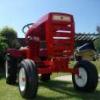
Wheel horse 227-5
Cub Cadet reacted to Scottwilson for a post in a topic
Well my daughter wants to join me at the shows and be more involved so I her grandad treated her to this . It’s an 1988 227-5 with the Kawasaki 540 engine . It’s been parked up in a barn for 3 years . Fresh petrol and a jump start and she runs fairly well . It will be a three way project between me,grandad and my daughter. FECC9D44-CEAE-47AD-A90E-6B8FA2453D25.MOV -
1 point
HALF a HORSE.
pmackellow reacted to Alan for a post in a topic
Turning brakes. I was undecided on these. Should I fit them, or not. OK, I'll make a start. Bent up a pair from alloy using photo's and guesswork as a size guide. The levers ? were from 1/8" x 1/4" brass drilled and tapped 8BA. Each lever was made in two parts as attempts to bend as per the full size resulted in a break. Brass too hard. Should have tried heating up first. These levers are probably a bit narrow, 3/8" would have been better but nothing in stock. It was then decided to leave them for now and carry on with other bits and pieces. Lots of bits and pieces later, Iain slf-uk my head information provider, sent me photo's and measurements of the assembly so a restart was made. My original guesstimated alloy pedals were correct in height and the inside of the bent up lips, much to my surprise, but 1/4" short in length. This 1/4" is the model size measurement. Two new pedals were made and the horizontal brass section extended using a piece of plastic for quickness. A test assembly. All these parts were held together with 8BA countersunk bolts. Looks a bit messy on the photo's but all hidden later. A few holes were drilled in the wrong place, but not seen when finished. The pivot bar is brass tube with a plastic insert and a 3mm threaded rod. All bits which just happened to fit together without much work. The lower ends of the uprights were drilled and tapped to suit the rod and the tube notched to take the inner upright. Easier than making the tube in sections as per the full size, and as these pedals won't be working, a bit stronger. The locking bar was also fixed in position. The notch in the tube was later filled and blended in. Various other areas had the same treatment to tidy things up. The brake pull rods! were from alloy angle , bolted to the underside of the footrest for extra strength with the nearly visible end trimmed down. I had to alter my original footrest support and lay it flat with the alloy angles notched to clear, but as usual after doing all this a better and simpler solution popped up in my head, but leaving as it is. Photo below is before cutting notches for support clearance. The full size has a steel bar running diagonally under the footrest, from the outer end of the pivot tube to the chassis frame, which helps support the tube. I made up a short alloy bracket which is bolted to the support angle in front of the pedals, and to the front underside of the footrest. Not really visible without effort. Hope all this makes sense. Grip tape was added to the pedals which finished them off as well as hiding all the bolt heads. The footrests also had a covering of the same. This self adhesive tape was listed on eBay as carpet gripper tape. Similar stuff also used for skate boards. I wanted to use ribbed rubber but nothing suitable found. All too thick. The next photo's show various stages of test fits. I could have left the cranked ends straight on the brake rods ! by moving them closer together, but had previously drilled the footrest and didn't want to waste the holes. Photo below. The pins connecting the rods to the uprights were made from a bolt, turned down and drilled, then cut to length. The split pins are 1mm diameter. The threaded end was screwed into the alloy rods after tapping and held with a dab of lock tight. A fiddly job inserting the split pins, especially the inner one resulting in chipped paint, now touched up. Might have been easier before fitting to the tractor. Not too happy with the appearance of these split pins. Need tidying up and the loop made smaller. A job for another time. A few more photo's of the various parts, mounting brackets, footrest support etc plus the unit finally fitted. -
1 pointHeadlights continued. The mount was from alloy sheet. White border painted on. Will look better with a decal fitted. The two holes were the first attempt at mounting the headlights via a bolt through the original painted reflector. After scrapping this idea holes were cut using a large washer as a guide. Easier than expected using a very fine saw but had to take care not to damage the paint too much. Should have thought of plan 2 before painting. Next are the lights with plastic retaining rings held onto the rim with very small self tappers. These three photo's show the lights fitted, then the rings painted. Also showing the bulbs which are just a push fit. These appear to look cross eyed on the front view. As said previously, these lights were worked on over approx one year on and off, trying different idea's etc. The next photo's show hub caps which were quick and simple and were only made / altered recently. Jumping the gun a bit here but not to worry. Looking around for something suitable the cap from a deoderant bottle was found to be a good fit over the wheel hubs. Black plastic which was painted white. The end didn't have a sharp edge which would have made painting the red easy so plastic discs were cut and fitted using small expanding rivets which I had a stock of. Three more bottles were obtained which gave the required four. The result, better looking wheel hubs and a nicer smelling wife. OOP's, shouldn't have said that. The discs mounted on a rod ready for painting. The four stages and the rivets. Front and rear wheels with caps. The fronts were a nice push fit but the rears wouldn't go over the hub weld without stretching resulting in chipped paint. A few spots of glue cured this.