I haven't yet as I keep forgetting to measure the gudgeon/wrist pin. It's also going to need a set of early type starter dogs as well as a complete replacement blower/starter cover.
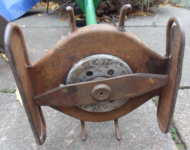
I have seen anything like it either, the brackets look a bit homemade to me, I wonder if it has been in something radio controlled as both the carb & governor vane are missing, the brackets seem quite long though.
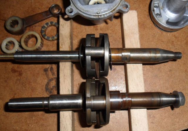
As for the engine I have come to the conclusion that it cannot be repaired without the correct piston, as both the conrod & crankshaft/backshaft are completely different to those from a later engine. This is due to the redesign they did to change all the bearings. The later one is at the bottom of the picture.
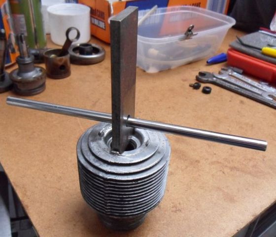
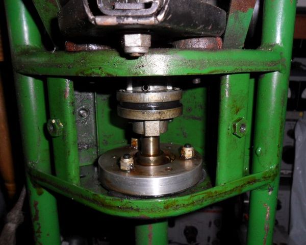
Here is the cylinder removal tool I made, which is similar to the one shown in the engine maintenance manual.
The instructions given are to make it from a piece of flat steel 3/16" thick & 1" square, with a hole drilled in the middle for using a screwdriver as a "T" handle.
The piece of steel & the bar I used came from a box of offcuts & salvaged bits in the shed. I didn't bother to make it 1" square though, I only squared up the ends and drilled the hole for the bar.
Leaving it a bit longer allows the tool to be clamped in a vice for cylinders that are too tight to remove by hand.
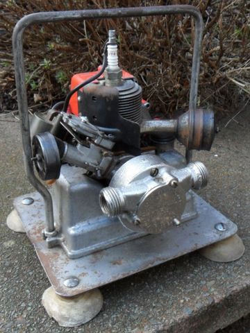
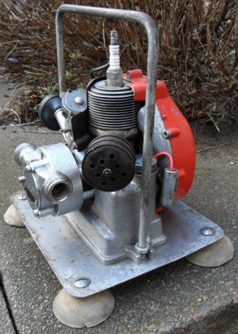
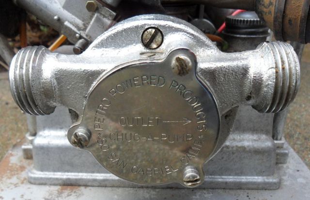
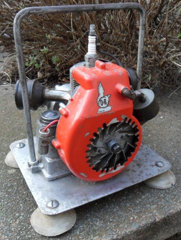
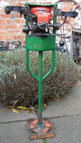
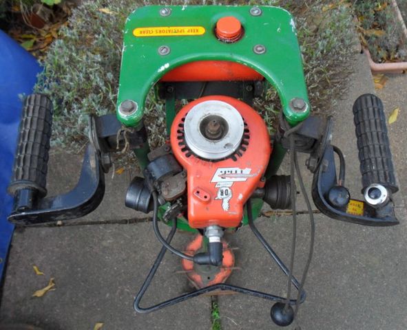
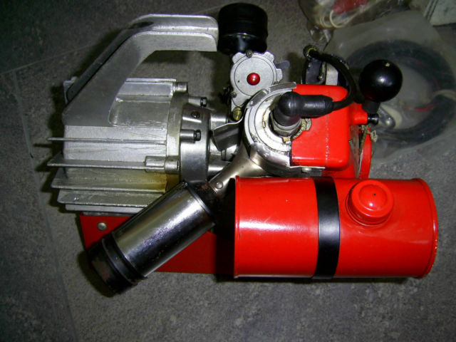
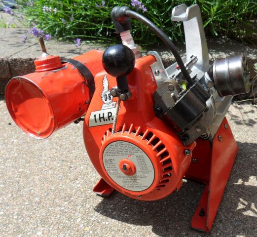
This is the latest addition to my O&R collection, a Petro Powered Products Chug-A-Pump.
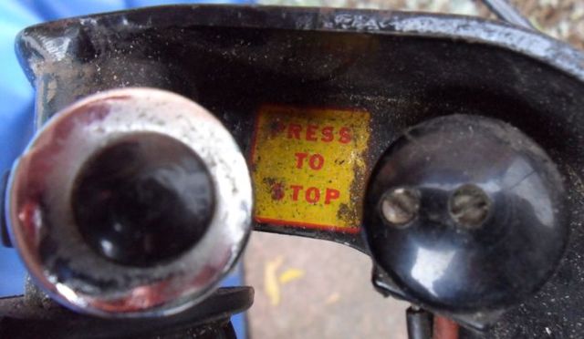
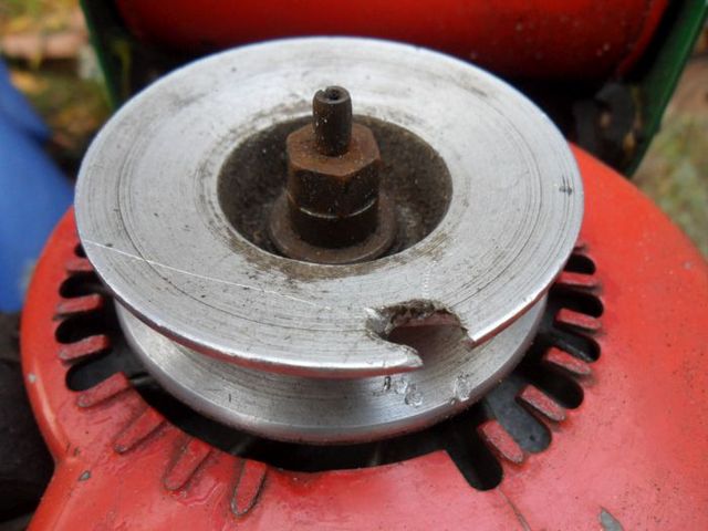
The engine is an early compact I with the side mounted carb needle & screws in the back of the starter/blower cover.
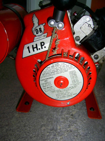
Unfortunately a previous owner disliked the starter mechanism so much that they cut it off completely.
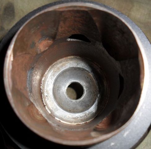
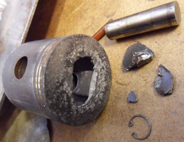
The engine was also seized & the flywheel nut threads were stripped, fortunately the crankshaft threads are OK. After removing the sparkplug I discovered someone had tried and failed to unseize it by hammering the piston with a rod, the piston has a hole in it. I left it overnight with some oil poured in the cylinder.
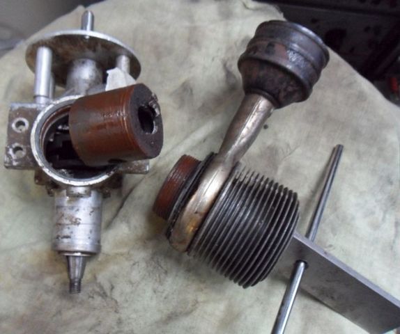
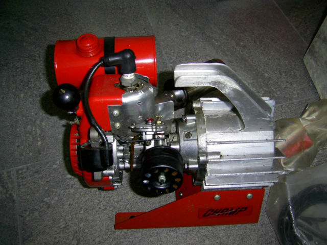
Today I stripped it down further, I was surprized to find the flywheel key was steel, it does have a different part number to the later engines so may be original? The oil left in overnight did the job and I was able to turn the flywheel a bit, which enabled me to remove the cylinder without damaging the conrod. The cylinder is a bit rusty but hopefully it will clean up for reuse. The missing bits of the piston were shaken out of the crankcase.
The gudgeon pin is also different to the later engines as it is solid, it is also smaller in diameter, I have a few spare pistons but they can't be used because of this.
I had one of these shipped over the pond and thought I'd might never see another.
I also started to try and remake the labels for when ever I get around to painting it. Here are some that were made using Microsoft paint program so the edges are not as crisp as I'd like but should work if you want to get someone to make them for you.
I only knew it was made by Kemm as I saved the pictures of yours when it sold last year. I didn't think I would see another either!
Thanks for posting those recreated decals, I will have to try making some decals for the coupling covers when it gets restored next year.
Here is the other intact decal on my grass cutter.
That's an interesting machine David, thanks for posting about it... I'm guessing from the lack of wheels you have to lift/drag it to cut the brush?
I guess you would use it the same way as a modern strimmer/brush cutter, although its probably a lot heavier.
These posts are from the old forum thread for setting the carb needle.
Original post by Webhead.
"1 and 1/4 out for starting. I have had units run good between 3/4 and a full 2 turn
out."
Original post by usedtoolman.
"If I recall there is one more factor on the needle setting. If you have a slotted needle
the setting is 1/2 turn as opposed to 1-1/4 for the non grooved needle."
Original post by Webhead.
"I have a service bulletin in my dealer's manual that notifies all techs to remove the
screen from the carb, on any engines that they worked on. Apparently the screen
getting clogged caused more problems than if there was no screen at all. The later
carbs were completely void of the screen."
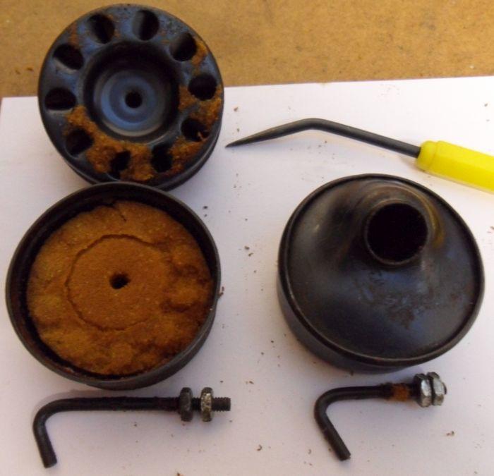
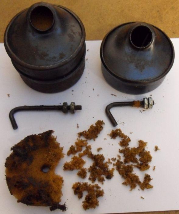
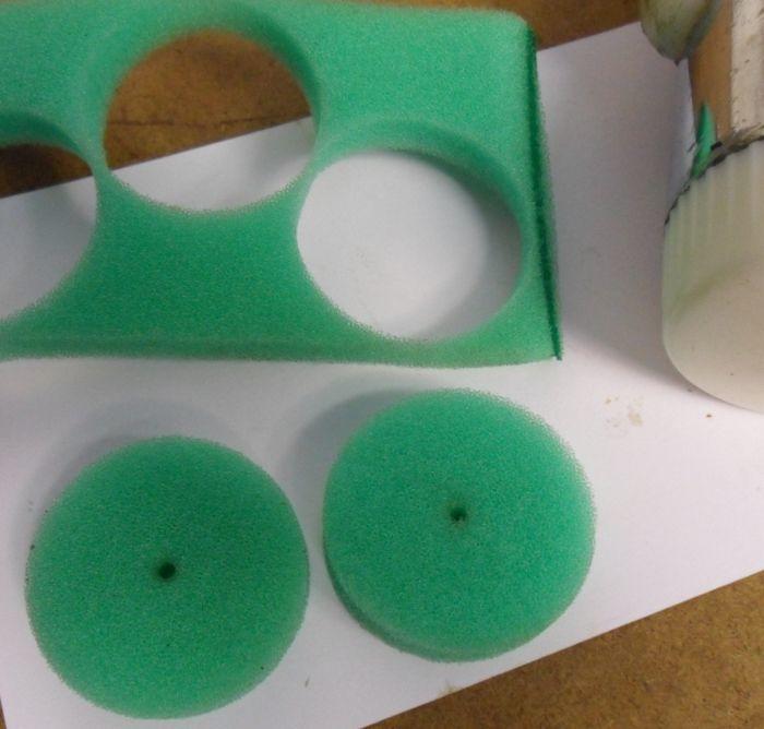
Filter Foam
Don't forget to remove and clean out all traces of the old air filter foam while you have the carb apart.
The early engines only have one section which doesn't come apart, the later ones have an extra section as shown in the pictures.
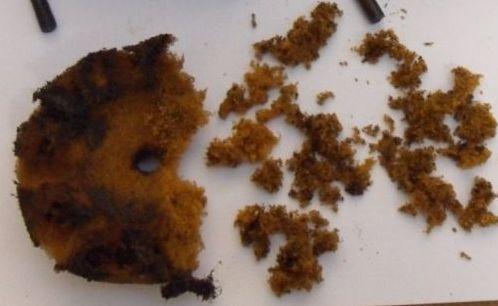
If the filter foam has already disintegrated and got sucked into the engine it can cause damage to the cylinder & piston.
New filters can be easily made by cutting them out from a larger piece of new filter foam (such as the pre-filter below, that I got from my local lawnmower repair shop).
Fuel Mix
We recommend a fuel mix ratio of 32:1, using non-ethanol gas/petrol (aka non-oxy) and mixing it with a good quality mineral based 2-stroke oil (such as the red color Stihl HP mineral oil, other brands are available).
USA, contact either @Wallfish or @CNew by personal message (PM).
UK & Europe, contact me @factory by personal message (PM).
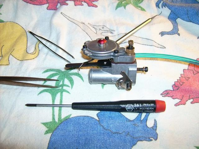
O&R Carb Repair Tutorial
The tutorial below was copied from the original thread from the old forum saved by the internet archive, tutorial courtesy of laserscottman.
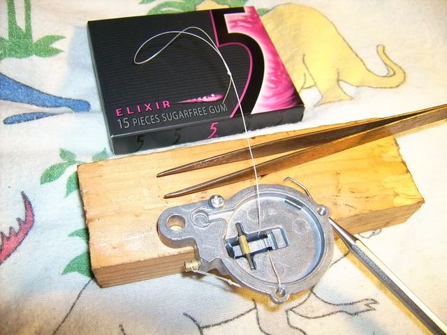
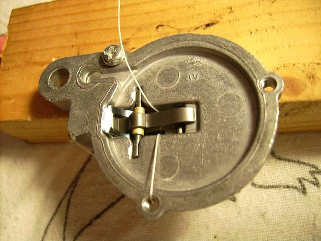
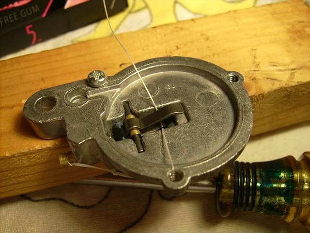
Here we go! The first pic in this thread shows how it all began. Following are the things I encountered along the way, during cleaning. After receiving the new diaphragm in the mail, I fully used Webhead's excellent instructions to reassemble the Primer/Diaphragm Valve Assembly successfully, with the following pictures detailing how I understood it. Got a block of soft wood and gently screwed the valve body down to hold it still to work on it. Fashioning a suitable 'filament' to thread through as shown, the filament is then used to lift the Diaphragm Arm Spring ends to allow the Diaphragm Roller to be laid in it's place at the right time in the assembly sequence. Then the Disc, Diaphragm and Cover are assembled.
The gum package is just a dark background to show the loop on the filament end to better grasp it. A non-magnetic pair of tweezers helped lay the roller in when it was time. The dental tool made it easy to pull/lift/move the Diaphragm Arm Spring to the various positions during assembly.
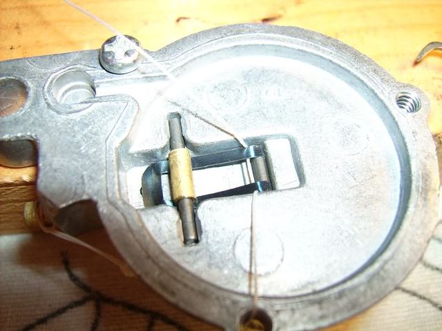
This is a detail view of how the spring will end-up over the roller in the end. Good practice to 'feel' how those spring ends will react to the filament tugging them.
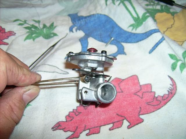
Now the Spring is lifted and stays at this position, to allow for installing the Diaphragm Arm. Note that the Roller and the Diaphragm Valve Ball are in place before the Arm is laid in place.
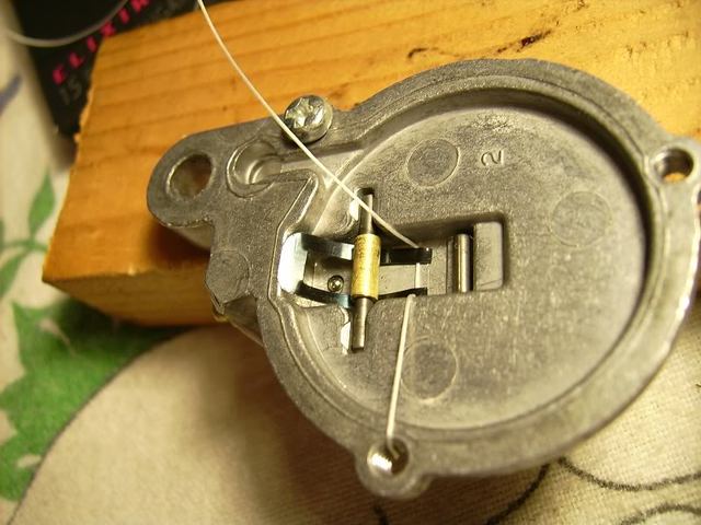
The next part is tricky. Using the dental tool to push the Spring over the Lever toward the Roller, you must help the Spring tips over the Roller by using the filament, and helping the Lever to stay draped over the cross pin, until the big end of the Spring is seated well in the Lever short end, and the Spring ends are capturing the Roller. All this is done kind of simultaneously, according to the position of the parts. You will be glad you only need 1 hand to hold the filament, and that you have a fine tool like the dental tool!
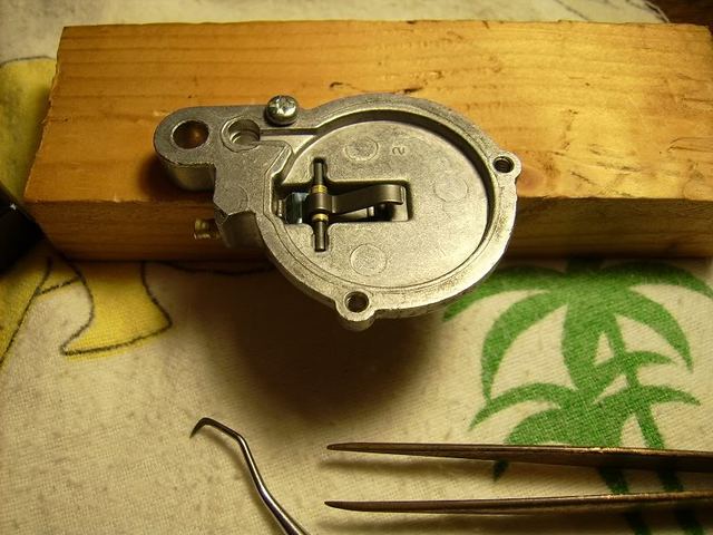
Perfectly aligned, and will stay if the Lever Arm is not lifted all the way up--which is what got me in this jam in the first place! Now, you must carefully remove the filament. I cut the long end near the Lever Arm, and gently removed the filament.
There it is!
Then you can sequentially assemble the remaining parts. Be sure to install the screws with fingers, loosely, to avoid bunching up the Diaphragm in the threads. Don't overtighten the screws; the cover can be warped a bit, and may "bite" through the rubber Diaphragm.
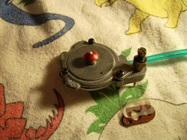
This assembly then gets the thick Gasket and Diaphragm Valve installed with the clear plastic valve against the body, covering the hole. This is a one-way valve that opens and closes rapidly during operation.
The Needle Valve Assembly and the long screw mount the Primer Diaphragm Valve Assembly to the "Quadrant" Carburetor Assembly (carb body). Remember you are tightening a hollow brass part to an aluminum part! Snug, but not overly so. Kinda looks like the Starship Enterprise, don't it? Now this Dinosaur fits in among his smiling friends!
Little, but MIGHTY!
Many thanks to Webhead for his patient guidance and sharing of parts and resources! And thanks for this forum! Cheers!
Extra Information
Another important post courtesy of Webhead who you can contact on here to buy replacement carb diaphragms.
"One thing that Scott mentioned that is VERY important- do not over tighten the brass needle valve assembly! I use a nut driver and give it a slight snug. In my earlier days, I snapped off two or three by using a 5/16" wrench. With a wrench, it seems like you always want to give it a little more and then snap!"
I bookmarked the forum a few weeks ago after googling 'Kemm trimmer' as I have just bought one. Will post some pictures of it later in the week.
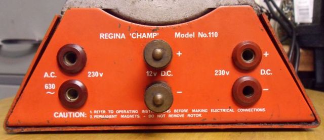
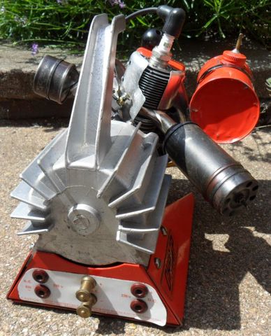
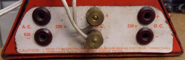
Here is a picture of the connector panel on the other Regina Champ I have, the rest of it is the same as the other one except it is a Model 110 & the details are decals instead of the sticker on the other.
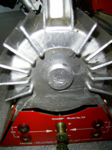
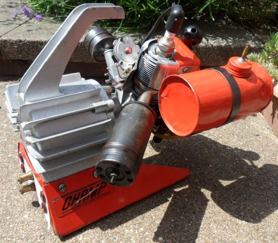
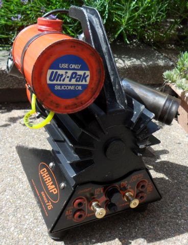
And another one I don't own, a new unused Model 114 12V/24V version, which made over £300 on ebay in 2013.
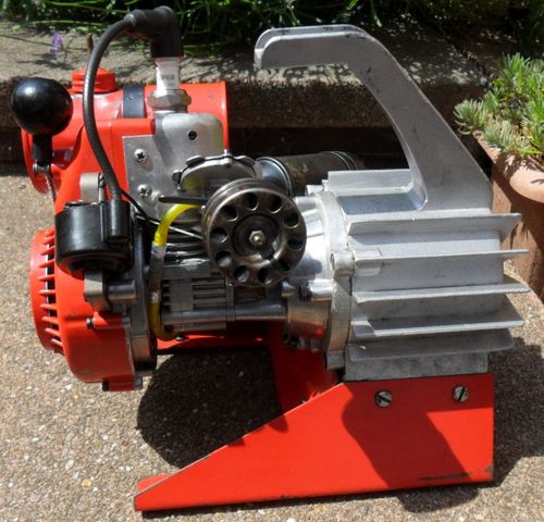
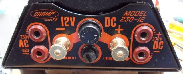
The Amp Champ, which has the same alternator (but 110V) has a maximum output of 350W, these should be the same. Overloading them will result in the alternator windings burning out. I usually run them with a lower load, of 150W to 200W.
The K.C. Wiggins version has fuses to protect from this, but doesn't indicate what value of fuses should be fitted. I put a 1.5A fuse in the 230V output.
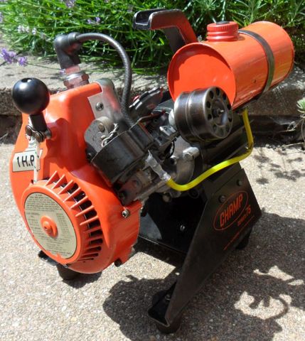
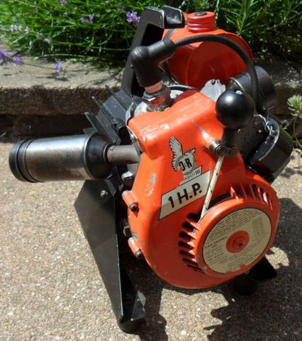
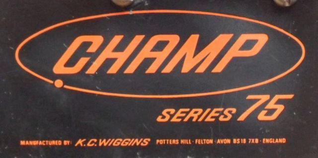
Here is my K.C. Wiggins Champ Series 75 that I restored earlier this year, this is a 230V output version of the Champ generator made in Potters Hill, Felton, near Bristol.
Be aware that forcing incorrect two pin plugs into these generators may break the plastic part of the sockets, resulting in the socket falling inside. I have seen several of these generators sold on ebay this year with broken sockets.
I'm not sure what plug was supplied with these when new, but all my UK two pin plugs have a pin spacing that is too wide, I ended up modifying one with a Dremel to fit without causing damage.


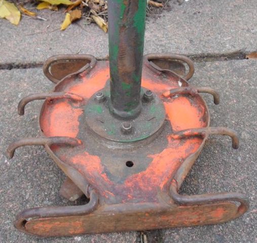


Petro Chug-A-Pump
in Ohlsson and Rice
Posted
I haven't yet as I keep forgetting to measure the gudgeon/wrist pin. It's also going to need a set of early type starter dogs as well as a complete replacement blower/starter cover.
David