

Anglo Traction
-
Content Count
1,124 -
Joined
-
Last visited
-
Days Won
144
Reputation Activity
-

 Anglo Traction got a reaction from Stormin in BSA Power unit
JimStDavids, If you click (or hover the cursor) on Paul's name on the left of his post, it will open another window and give you the opportunity to send him a personal message.
If he has enabled this in his settings, it will give him a notice of your mssge in his Email inbox and prompt him to visit this forum again .
-

 Anglo Traction got a reaction from JimStDavids in BSA Power unit
JimStDavids, If you click (or hover the cursor) on Paul's name on the left of his post, it will open another window and give you the opportunity to send him a personal message.
If he has enabled this in his settings, it will give him a notice of your mssge in his Email inbox and prompt him to visit this forum again .
-
 Anglo Traction reacted to Fix'em all in Merry Tiller
Despite the weather I still nearly finished this project at the weekend
-
Anglo Traction reacted to rolloman 1 in Holder ED11
Hi all Yet some more pictures of exhibits for 2019, My Holder ED11 Single axle tractor with Butterfly Reversible plough and 3rd wheel and seat, had it a long time too also again 2 owner from new. Powered by a Sachs 500 Two stroke diesel of 9 hp water cooled thermo syphon no pump 4 forward and 1 reverse , It runs like a Clock I havent found any of these in the uk so far hope you like it i love it
-
Anglo Traction reacted to HeadExam in Another Chainsaw Restoration
This is a XL-102 Automatic, its a 1970 saw weighing 11 pounds and has 57cc with auto oiler and manual over ride. These were only made in 1970 and 1971 I have one from both years. I couldn't get NOS decals so I had to do the best I could. Still need to install the carb and find a appropriate spot on the shelf. Last picture is what the saw looked like before
-
Anglo Traction reacted to Stormin in BSA Power unit
Pauls not been on here since July 2017. Hopefully someone may know where he is and let him know.
Paul at Meetens may be able to help you. He's quite a clued up and helpful chap. Google Meetens to get in touch.
-
-
Anglo Traction reacted to mattblack in Villiers MK15
Made a bit more progress.
The carb was a bit crusty inside. looked like it may have had water sitting in it but it cleaned up OK.
coming back together.
Cleaned up the tank and cowling and filled the dents.
-
Anglo Traction reacted to HeadExam in Kohler TP manuals
I have become aware that many do not have the Kohler TP manuals that show all the variants on different Kohler engines and how to find the right part. The best way to tell is to download the Kohler TP manual on each engine model (or your engine) and compare part numbers, There are two sump pans for the K301 and K341 that interchange, but there are many more that don't. It depends on what tractor and engine as much as the horsepower . The TP manuals show all the various parts used on each engine i.e. all the starters and generators used on the all the different k301 variants, all the oil pans, carburetors, dipsticks, alternators, air breathers, etc. There is also a numerical system incorporated in the TP manuals that allows you to know what part was used on your variant by the use of the spec number that is on the engine. This is all basic reference 101 and saves much times and money in finding parts that actually fit. Attached is the TP manual for the Kohler K301. This manual covers dozens of K301 variant engines and if the "spec number" sticker is missing from your engine there is a website that you can find it. If anyone one wants TP manuals for other Kohler engines let me know
Kohlerl_K301_12HP_IPL_TP2097.pdf
K321_14HP_TP-691-B.pdf
K341_16HP_TP-983-B.pdf
-
 Anglo Traction got a reaction from Cub Cadet in A Mystery Roaring Twenties Refurb.......hopefully!
Only too aware Ray that running clearances in engines need to be as recommended to avoid nasty noises and disintegration. Just a matter of cleaning the old dry oily dirt
off with scrapers and soft wire brushes, then finishing with a bit of soft scouring pad. It's not super polished, as I don't want it looking new.
Starting handle in the previous post is reassembled, greased the tubing/handle before pressing back on. ready for painting.
Returned to checking out the ignition bits to see what was needed. Having obtained the HT Coil and Lead, I started on the Points Box and when I opened it up,
I found it surprisingly tidy-
Clearly, towards the end of it's working life, it was opened up quite a lot judging by the scratches on the bright, heavy nickel plated lid.
Repairs had been attempted by the use of hard (red) sealing wax to act as insulation under the screw head. The small insulating bushings were originally made of 'Ebonite',
a hard vulcanised rubber shaped under high pressures. These had broken and cracked under the screws, but the spacer bushings underneath the plate were ok.
I set about making new flanged bushings that would fit with the engine's age, and I remembered I had a rod of 'Tufnol' from the 50s that was my Father's.
Good stuff this, but never machined it, so did some checking up first. Also found this Ad from the mid 1930s-
This stuff was being made before the company was formed and is used on the 'Heel' of the breaker points on this engine (which may need replacing).
The rod is surprisingly close tolerance in diameter ( 0.001" under 1/2") and dead straight. This version is known as 'Carp'.
Fine woven cotton fabric tightly rolled, soaked in resin and pressed until set. Cut a piece off, set it in the Baby lathe and turned down to outer diameter-
Clearance drilled for 4BA Screws, then turned down each one to 1/4" (6.35mm) and parted off. I used white spirit as a lubricant and helped reduce
the dust level (mask and vacuum used). Cleaned up the part machined cast brass Points box.
The wires are all still good. Finished bushes seen here and re-using the original spacers-
The worn breaker heel (circled in the above) on the original points arm can be fabricated from this tufnol if I find the wear is too great for points adjustment.
The arm and both contacts have so little wear, that I only had to lightly mirror polish the Platinum faces. Virtually no pitting, which tells me that the condenser
was working as it should when last run. I plan to get this running with all these parts initially.
Will attempt some repairs to the enamelled badge that fits in the Flywheel cover. Also need to repair the worn slots in the lightly cleaned up cover-
-
Anglo Traction got a reaction from Cub Cadet in MF7E Refurb project
Good luck Ewan, I'll be following your progress .
-
Anglo Traction got a reaction from Stormin in A Mystery Roaring Twenties Refurb.......hopefully!
Only too aware Ray that running clearances in engines need to be as recommended to avoid nasty noises and disintegration. Just a matter of cleaning the old dry oily dirt
off with scrapers and soft wire brushes, then finishing with a bit of soft scouring pad. It's not super polished, as I don't want it looking new.
Starting handle in the previous post is reassembled, greased the tubing/handle before pressing back on. ready for painting.
Returned to checking out the ignition bits to see what was needed. Having obtained the HT Coil and Lead, I started on the Points Box and when I opened it up,
I found it surprisingly tidy-
Clearly, towards the end of it's working life, it was opened up quite a lot judging by the scratches on the bright, heavy nickel plated lid.
Repairs had been attempted by the use of hard (red) sealing wax to act as insulation under the screw head. The small insulating bushings were originally made of 'Ebonite',
a hard vulcanised rubber shaped under high pressures. These had broken and cracked under the screws, but the spacer bushings underneath the plate were ok.
I set about making new flanged bushings that would fit with the engine's age, and I remembered I had a rod of 'Tufnol' from the 50s that was my Father's.
Good stuff this, but never machined it, so did some checking up first. Also found this Ad from the mid 1930s-
This stuff was being made before the company was formed and is used on the 'Heel' of the breaker points on this engine (which may need replacing).
The rod is surprisingly close tolerance in diameter ( 0.001" under 1/2") and dead straight. This version is known as 'Carp'.
Fine woven cotton fabric tightly rolled, soaked in resin and pressed until set. Cut a piece off, set it in the Baby lathe and turned down to outer diameter-
Clearance drilled for 4BA Screws, then turned down each one to 1/4" (6.35mm) and parted off. I used white spirit as a lubricant and helped reduce
the dust level (mask and vacuum used). Cleaned up the part machined cast brass Points box.
The wires are all still good. Finished bushes seen here and re-using the original spacers-
The worn breaker heel (circled in the above) on the original points arm can be fabricated from this tufnol if I find the wear is too great for points adjustment.
The arm and both contacts have so little wear, that I only had to lightly mirror polish the Platinum faces. Virtually no pitting, which tells me that the condenser
was working as it should when last run. I plan to get this running with all these parts initially.
Will attempt some repairs to the enamelled badge that fits in the Flywheel cover. Also need to repair the worn slots in the lightly cleaned up cover-
-
 Anglo Traction got a reaction from Alan in A Mystery Roaring Twenties Refurb.......hopefully!
Only too aware Ray that running clearances in engines need to be as recommended to avoid nasty noises and disintegration. Just a matter of cleaning the old dry oily dirt
off with scrapers and soft wire brushes, then finishing with a bit of soft scouring pad. It's not super polished, as I don't want it looking new.
Starting handle in the previous post is reassembled, greased the tubing/handle before pressing back on. ready for painting.
Returned to checking out the ignition bits to see what was needed. Having obtained the HT Coil and Lead, I started on the Points Box and when I opened it up,
I found it surprisingly tidy-
Clearly, towards the end of it's working life, it was opened up quite a lot judging by the scratches on the bright, heavy nickel plated lid.
Repairs had been attempted by the use of hard (red) sealing wax to act as insulation under the screw head. The small insulating bushings were originally made of 'Ebonite',
a hard vulcanised rubber shaped under high pressures. These had broken and cracked under the screws, but the spacer bushings underneath the plate were ok.
I set about making new flanged bushings that would fit with the engine's age, and I remembered I had a rod of 'Tufnol' from the 50s that was my Father's.
Good stuff this, but never machined it, so did some checking up first. Also found this Ad from the mid 1930s-
This stuff was being made before the company was formed and is used on the 'Heel' of the breaker points on this engine (which may need replacing).
The rod is surprisingly close tolerance in diameter ( 0.001" under 1/2") and dead straight. This version is known as 'Carp'.
Fine woven cotton fabric tightly rolled, soaked in resin and pressed until set. Cut a piece off, set it in the Baby lathe and turned down to outer diameter-
Clearance drilled for 4BA Screws, then turned down each one to 1/4" (6.35mm) and parted off. I used white spirit as a lubricant and helped reduce
the dust level (mask and vacuum used). Cleaned up the part machined cast brass Points box.
The wires are all still good. Finished bushes seen here and re-using the original spacers-
The worn breaker heel (circled in the above) on the original points arm can be fabricated from this tufnol if I find the wear is too great for points adjustment.
The arm and both contacts have so little wear, that I only had to lightly mirror polish the Platinum faces. Virtually no pitting, which tells me that the condenser
was working as it should when last run. I plan to get this running with all these parts initially.
Will attempt some repairs to the enamelled badge that fits in the Flywheel cover. Also need to repair the worn slots in the lightly cleaned up cover-
-
Anglo Traction got a reaction from Alan in A Mystery Roaring Twenties Refurb.......hopefully!
Called a deflector piston. Pretty heavy as well. weighs in at 520 grams without the Pin. Villiers used them a lot up to about 1934. then went flat top on most 2 stroke motorcycle engines when they modified the size and layout of the porting.
Still used deflectors on the 79 Mk1 & 98cc Midget Mk's 2 & 3 engines which ended up in mowers etc like in my Yellow Mower challenge Atco-
The Skirt ring must have been discontinued in this 269cc MkV during 1922, as the donor engine later of the same year had the same piston, but unmachined for the fitting of that ring.
Thanks Ewan, It's making a pleasant change trying to save something that just under a hundred years old.
Main parts of the power unit are back together now and feels nice with the movement-
Working on the ignition bits now, but broke off to play with the all important starting handle. Pretty badly rusted up, but was able to dismantle into it's constituent parts.
The top 3 parts in this pic, where the free turning hand grip tube was seized (frozen) onto the handle. The lower part is one of the control arms which needs attention-
I had to carefully cut the old piece of tubing off, as it was solid and beyond saving. Searched for a substitute and found some stainless tubing that would just about fit.
Being sold in 100mm lengths, I asked if I could have a piece 101.6mm (4 inches) and it arrived within 24hrs exactly 4 " long !!. Impressed.
Went for stainless, as I reckoned the original was bright nickel plated steel. This will look ok. Initial clean up and prep required me to machine about 3 thousands of an
inch off the 2 faces for the tube to fit on smoothly. Parts to finish and assemble. Even the Cotter Pin was nickel plated, but needed a new nut-
Got some more machining to do before I finish the igntion bits.......tbc.
-
Anglo Traction reacted to Cub Cadet in MF7E Refurb project
Afternoon all, After a few busy months I finally had the chance to make a start on the massey! The aim is to get it running for a show late in July.
Heres some before photos in case you forgot
First job was to get the front up on some axle stands, remove the hood and front wheels. The steering needs some work as everything is very worn.
it needs some serious degreasing as well so the engine was next to come out, it also helps to have the engine on a bench as it will need a partial strip down.
here you can see just how worn the axle is, it is a very lightweight casting and unfortunately it is a bit twisted.
Next I made a new bush for the axle, should work just fine.
after a bit of cleaning up. the original paint is in excellent condition, just a shame someone painted over it.
These are going to require some attention at some point.
On closer inspection, one of the engine mount holes has cracked, just visible above, now welded up.
The idler pulley and steering column was removed and then everything given a good clean.
For a 56 year old machine, i'm surprised nothing is rusted solid, didn't even have to use any heat.
Next job when i'm home next is to replace the bearing in the idler pulley and sort out the worn steering components.
-
Anglo Traction got a reaction from Cub Cadet in A Mystery Roaring Twenties Refurb.......hopefully!
Called a deflector piston. Pretty heavy as well. weighs in at 520 grams without the Pin. Villiers used them a lot up to about 1934. then went flat top on most 2 stroke motorcycle engines when they modified the size and layout of the porting.
Still used deflectors on the 79 Mk1 & 98cc Midget Mk's 2 & 3 engines which ended up in mowers etc like in my Yellow Mower challenge Atco-
The Skirt ring must have been discontinued in this 269cc MkV during 1922, as the donor engine later of the same year had the same piston, but unmachined for the fitting of that ring.
Thanks Ewan, It's making a pleasant change trying to save something that just under a hundred years old.
Main parts of the power unit are back together now and feels nice with the movement-
Working on the ignition bits now, but broke off to play with the all important starting handle. Pretty badly rusted up, but was able to dismantle into it's constituent parts.
The top 3 parts in this pic, where the free turning hand grip tube was seized (frozen) onto the handle. The lower part is one of the control arms which needs attention-
I had to carefully cut the old piece of tubing off, as it was solid and beyond saving. Searched for a substitute and found some stainless tubing that would just about fit.
Being sold in 100mm lengths, I asked if I could have a piece 101.6mm (4 inches) and it arrived within 24hrs exactly 4 " long !!. Impressed.
Went for stainless, as I reckoned the original was bright nickel plated steel. This will look ok. Initial clean up and prep required me to machine about 3 thousands of an
inch off the 2 faces for the tube to fit on smoothly. Parts to finish and assemble. Even the Cotter Pin was nickel plated, but needed a new nut-
Got some more machining to do before I finish the igntion bits.......tbc.
-
Anglo Traction got a reaction from Stormin in A Mystery Roaring Twenties Refurb.......hopefully!
Called a deflector piston. Pretty heavy as well. weighs in at 520 grams without the Pin. Villiers used them a lot up to about 1934. then went flat top on most 2 stroke motorcycle engines when they modified the size and layout of the porting.
Still used deflectors on the 79 Mk1 & 98cc Midget Mk's 2 & 3 engines which ended up in mowers etc like in my Yellow Mower challenge Atco-
The Skirt ring must have been discontinued in this 269cc MkV during 1922, as the donor engine later of the same year had the same piston, but unmachined for the fitting of that ring.
Thanks Ewan, It's making a pleasant change trying to save something that just under a hundred years old.
Main parts of the power unit are back together now and feels nice with the movement-
Working on the ignition bits now, but broke off to play with the all important starting handle. Pretty badly rusted up, but was able to dismantle into it's constituent parts.
The top 3 parts in this pic, where the free turning hand grip tube was seized (frozen) onto the handle. The lower part is one of the control arms which needs attention-
I had to carefully cut the old piece of tubing off, as it was solid and beyond saving. Searched for a substitute and found some stainless tubing that would just about fit.
Being sold in 100mm lengths, I asked if I could have a piece 101.6mm (4 inches) and it arrived within 24hrs exactly 4 " long !!. Impressed.
Went for stainless, as I reckoned the original was bright nickel plated steel. This will look ok. Initial clean up and prep required me to machine about 3 thousands of an
inch off the 2 faces for the tube to fit on smoothly. Parts to finish and assemble. Even the Cotter Pin was nickel plated, but needed a new nut-
Got some more machining to do before I finish the igntion bits.......tbc.
-
Anglo Traction reacted to Cub Cadet in A Mystery Roaring Twenties Refurb.......hopefully!
Nice work Richard!
-
Anglo Traction reacted to Stormin in A Mystery Roaring Twenties Refurb.......hopefully!
Coming along nicely, Richard.
I've just noticed the piston crown. I've worked on a few two strokes, but never come across a piston like that. Or with a ring at the bottom.
-
Anglo Traction got a reaction from Cub Cadet in A Mystery Roaring Twenties Refurb.......hopefully!
Having done some swatting up on machining this version of Phosphor Bronze (PB104) and looking for more endorsements that it is the correct stuff for the job, I went ahead.
The Gudgeon Pin obtained from the donor engine was a god send, as I had visions of having to make one and pay for the cylindrical grinding and polishing to size.
I went all over it with a micrometer, noting and marking sizes. I found a slight taper of 0.0002"(0.0051mm) end to end.
The most wear I found was 0.0006" (0.0152mm), so I aimed for closest fit possible to that. Strangely, the pin diameter is neither metric, or imperial and so worked to 0.4915" -
Started with 3/4" (19.05mm) dia stock rod. I knew the stuff was a bit 'sticky' when machining. Using 1 part cutting oil and 10 parts White spirit (mineral spirits I believe in U.S)
I followed a set process of repeated shallow depth drilling, followed up by boring and progressively enlarging the bore to keep the friction heat down. Stayed only warm to the touch throughout, so was happy with that.
Got to 31/64" (0.4843") leaving me about 0.0072" to finish. Moved the part still in the chuck over to the Mill and fitted to the rotary table for marking out and drilling the oil way-
You may see on the old bushing, a circle just below the oil way. Well I scribed the circle while it was still in the con rod due no hole visible.
It was not until I removed the bushing that I found the oil way there. So either it was originally fitted like that, or it moved round ?.
Anyway. after drilling the hole, it was back to the lathe with it to finish the bore to size and turn the outer diameter to a press fit-
Put shallow helical groove in the bore for oil distribution, then parted off and finished ready for fitting-
A bit of relief to get that part out of the way, so continued to chip away at various bits. Tank Cap was plugged, fuel tap was seized up and clogged.
Also has a filter in the lower section. All cleaned ready.
The back of the Armature Plate lightly cleaned to keep the age look and proceeded to make the rusted, rotted parts. Spring wire HT cap retainer and the armature plate lever. Both Oil blackened and heat treated. New HT Lead and ready now to fit the piston-
You may also notice the Lock Screw for the armature plate looks a bit better now.
The black markings on the piston are not wear or damage. I believe they are fine grinding marks from when it was either being prepped as a casting ready for machining, or after machining to allow for some skirt clearance and oil retention.
Carefully checked and marked the parts for correct orientation and order of assembly, starting with the small end bushing and avoiding any strain on the con rod and bearings-
That bushing should not move in a hurry now!.
And with another 'pre fit' check, the ceremonial oiling and fitting of the piston -
....................tbc
-
Anglo Traction got a reaction from Cub Cadet in A Mystery Roaring Twenties Refurb.......hopefully!
No Norm, I would not dare to do a blind 2 stroke cylinder with large transfer ports. Don't have the gear.
It should be done properly on a machine that limits the oscillating travel of the rotating (multi) stones at the right point and that the stones can't catch on the ports.
It should only really be done when the bore can be measured accurately to fit new rings so end clearance is minimal.
This bore surprisingly only had staining with no rust pitting or scoring, despite the engine being locked solid until my releasing fluid did the job and freed it up.
Thought I had a pic of the cleaned up bore, but can only find this one from after removing the cylinder-
I was really quite impressed with the smoothness of the cleaned up bore and struggled to find any wear lips or tram lines. I think the low skirt piston ring served to maintain even bore wear and prevented piston slap wear. The single replacement ring will have to bed in as is, but will be assisted with increase of Petroil ratio and 40 weight oil instead of 30 wt.
I was not happy with my attempts to clean the crank case out as much as possible without splitting the cases.
After several attempts to remove the drive sprocket from the Crank, I gave up.
It is worn, but serviceable for now and I could not position it in my 12 ton press to apply correct force properly without risk of strain or damage to it.
So I split the cases which showed the cleaning limit lines-
Just as well I split them, as the oil galleries to the Crank bushings were solidly blocked with carbon, as well as the surfaces .
Armed with a few old toothbrushes etc, it all cleaned up nicely and very smooth shiny surfaces at the contact points.
Next pic shows that this engine was designed to run with the cylinder vertically.
The recessed valleys each side above the shaft bushings collect and channel oil to the galleries for lubrication.
They can't do that so well when it's in a horizontal plane. The other point is that the crank case drain plug is rendered useless!.
Another observation is the design of a separate lubrication facility where oil is passed into the crankcase via a hollow mounting stud or bolt, you can see the recess around the bolt hole in lower left and right positions of the case halves in the pic below-
The separate oil system is not used on this application, so uses premixed petrol and oil (petroil).
I checked the crankshaft end float before splitting the cases (0.0055" or 0.15mm), it's well within limits, so I measured the old washer (gasket) thickness and cut out a new one.
Quality brown paper was used with a thickness of 0.0045". Thought I'd stick to tradition and use shellac to dress the washer/gasket and bolted up the cases.
Left to set overnight, tweaked the bolts and checked the end float and got 0.006" . Real happy with that, so gave it some oil in the important bits.
Now that it was all clean, I could check the wear limits of the crank bushings. up, down, left and right movement on both sides using about 20 ft lbs (27.12 Nm) pressure.
Flywheel side was good with only around 0.005" in all points. Drive side was a bit excessive on the chain strain line (0.010") , but good up down and right.
Just as well as only option would be to make new one(s)......no thanks!.
Established the type of bronze I needed and ordered some PB104................................... TB Cont'd .
-
Anglo Traction got a reaction from Cub Cadet in A Mystery Roaring Twenties Refurb.......hopefully!
Well, I hope it provides some reading entertainment for you Gents. Afraid a simple 'Oily Rag' refurb has escaped me again Norm.
The cylinder had to have the various bits removed from it. Luckily, the completely blocked Decompression Valve relented ok and the bypass tube plug in the head undid,
but the eroded exhaust flange nuts had to be cut and split-
While still dealing with the Cylinder bits, I had to start searching for somewhere to have new Rings made. A few hours interweb searching later, I'd found reference
to a restoration of a 1922 CWS Federal Motor bicycle. It had the same engine as this one and reference was made to an engineering firm that did all the work including making new Rings!.
So I fired off an enquiry and received a good reply with price estimates for each item of work, i.e, a cylinder hone and 3 piston rings to fit.
Long story short, I built a strong protective box to transport the parts and to return them in it-
Disappointed to say the least after receiving an email saying 'all done' and sorry for the cost/charge as was more difficult than he expected!.
When it arrived, all they had done was to make one piston ring!.
They left the 2 old rings on which I sent for their pattern reference, did not hone the bore and charged double for one ring.
So with fingers burnt again (as some here will know) from remote commission work, despite endorsements, my faith in British engineering firms has diminished completely and will now only deal with 'face to face' arrangements.
No option but to proceed and have faith that the wear, although greater than stated limits, will be ok for it to run ok. The point being that it has been fully de carbonised and so loses some assistance the carbon can offer in compression retention.
Onward's we go, and started the servicing of the De-Comp valve. Solid with carbon and parts rusted away. Cleaned up and made new clamping screw for the lever pivot collar and pivot pin-
Valve seat and face cleaned up ok and only needed lapping with scrapings from p600 emery and 'T' cut. New valve nut, 1/16" cotter/split pin and will have new copper washer.
Lever pivot hole egg shaped, so bored it out larger and fitted a bronze bush (not in pic).
Next job was to obtain the correct type of bronze rod for the small end bushing................................... T B Cont'd
-
Anglo Traction got a reaction from Cub Cadet in A Mystery Roaring Twenties Refurb.......hopefully!
Well, perhaps just a subdued British 1920s refurb !
I'm hoping I'm not tempting fate here by starting this before I am confident it can be saved and bring back to working order, but I have reached a point where I am reasonably confident.
The intention is not just to keep this a mystery 'til near the end, but to document the challenges of working on what can only be described as an old garden sculpture that used to be a machine.
I reckon that this machine had a useful life of about 7- 10 years from early 1922. Thereafter, it was abandoned and left outside for at least 20 years with only the oil laden dirt to protect it.
It had later (in the mid 50s) been moved to inside an old van and stored there until it saw the light of day back in Sept 18. Always been in the original purchaser's family possession until then.
Being of the ilk that likes a challenge, this may be harder than I've been used to in the past. The engine is obsolete and I have no parts information for it, or the machine's frame.
I have acquired some excellent info on the engine and carburettor and has allowed me to progress with checking wear tolerances and set up.
I make no apologies for all the detail in the thread, as I hope it may be of use to anyone who also attempts to tackle an old Villiers engine etc.
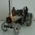
Work began on the engine to see if it was salvageable. This is the Villiers MkV 269cc 2 stroke of 1922.
It is the engine version that was first to use the flywheel magneto patented around 1920 by Villiers. Very simple and effective at that time-
Known as the large flywheel type Magneto (8 1/2" dia or 216mm), the engine had undergone several revisions since it's inception in 1913.
Designed originally for motor bicycles, this one has a variable timing Armature back plate, but has no use for this machine's application, as the ignition timing is for TDC!.
Flywheel is matched to this Armature Plate having identical numbers stamped on them.
Condition of the engine externally was badly corroded Fins etc on most upper parts, as you will see in various pics.
Internally was pretty dirty and no evidence of ever having been de-carbonised as it had a very thick layer inside the piston. Obviously the rings were seized after about 80 years-
This engine, being very early 1922 was still fitted with 3 Rings. Later 1922 engines appear to have only 2 at the top?. Production of this engine ceased in September of '22' .
I had suspected the wear in this engine to be quite bad, as it was designed to be upright and not horiziontally mounted, but was surprised that it was reasonably good as cleaning progressed.
Years of oily dirt helped to keep the corrosion down in certain areas which can be seen in this pic-
Note:- the chain was fitted to provide restraint while undoing the Crankshaft nut to remove the Fan.
Once the engine was liberated from the frame, the internals were dismantled. Piston gudgeon (wrist pin) pin is the 'Drive In/Out' type and locked with Cotter/Spit pins.
With this removed I found serious wear to the pin and con rod 'Small End' bushing. The cause being no oil hole visible to allow lubrication!.
Having been blessed with access to a donor engine of the later type (2 piston rings), I obtained a good and little worn gudgeon pin, but had no option other than to make a new 'small end' bushing.
I put that to one side while further evaluation was made. Cylinder and it's bore was cleaned and looked quite good considering and maybe just a hone required.
Despite virtually no scoring in the bore or the ring faces, the wear limit of the ring gap is excessive and really needs new ones and a hone. Piston is good.
Donor engine bore etc are poor condition.
Valuable information came by the way of old editions of 2 different books by motor cycle enthusiasts of the 30s onwards, namely Cyril Grange & B.E Browning.
Between the two books, I was able to extract all the max wear tolerances and most procedures.
I did have a problem finding the best way to remove the large brass retaining disc/washer that retained the Armature Plate. It also appeared distorted or cup shaped -
I was also concerned about the wear marks from the Flywheel on the armature plate's face, just visible top L/R of pic above.
Disc/washer was a press fit onto the Crankshaft, so I went carefully and used 2 small levers to evenly prize it away with the expectation of finding an oil seal of some type behind it, only to find nothing!.
Never had any oil seal fitted and no sign of leaks etc!!, all metal running fits. I reckon the cup shaped look of the washer was from strain of some kind and should be flat?.
At the same time, I had fears of the Lock Screw at the back of the Plate being totally seized, as it only has a screwdriver slot, or what was left of it-
I found the heftiest flat bladed lever I could use and to my surprise after a little of my releasing fluid, it unscrewed smoothly and the plate could be removed exposing the corrosion and rot-
The list of jobs was gradually increasing the more I delved, and the damage from it's last runs was appearing.
I tested the HT Coil using ohms resistance just to endorse it was dead, found there was still continuity in the 2nd winding, but only had half of the normal resistance. Going new anyway.
modern version of this pre WW2 HT Coil is available, as well as the HT Lead, but not cheap.
So by this point, I knew what was needed, what could be done and obtained to get this running again. ......soon to be cont'd.
-
Anglo Traction got a reaction from Alan in A Mystery Roaring Twenties Refurb.......hopefully!
Having done some swatting up on machining this version of Phosphor Bronze (PB104) and looking for more endorsements that it is the correct stuff for the job, I went ahead.
The Gudgeon Pin obtained from the donor engine was a god send, as I had visions of having to make one and pay for the cylindrical grinding and polishing to size.
I went all over it with a micrometer, noting and marking sizes. I found a slight taper of 0.0002"(0.0051mm) end to end.
The most wear I found was 0.0006" (0.0152mm), so I aimed for closest fit possible to that. Strangely, the pin diameter is neither metric, or imperial and so worked to 0.4915" -
Started with 3/4" (19.05mm) dia stock rod. I knew the stuff was a bit 'sticky' when machining. Using 1 part cutting oil and 10 parts White spirit (mineral spirits I believe in U.S)
I followed a set process of repeated shallow depth drilling, followed up by boring and progressively enlarging the bore to keep the friction heat down. Stayed only warm to the touch throughout, so was happy with that.
Got to 31/64" (0.4843") leaving me about 0.0072" to finish. Moved the part still in the chuck over to the Mill and fitted to the rotary table for marking out and drilling the oil way-
You may see on the old bushing, a circle just below the oil way. Well I scribed the circle while it was still in the con rod due no hole visible.
It was not until I removed the bushing that I found the oil way there. So either it was originally fitted like that, or it moved round ?.
Anyway. after drilling the hole, it was back to the lathe with it to finish the bore to size and turn the outer diameter to a press fit-
Put shallow helical groove in the bore for oil distribution, then parted off and finished ready for fitting-
A bit of relief to get that part out of the way, so continued to chip away at various bits. Tank Cap was plugged, fuel tap was seized up and clogged.
Also has a filter in the lower section. All cleaned ready.
The back of the Armature Plate lightly cleaned to keep the age look and proceeded to make the rusted, rotted parts. Spring wire HT cap retainer and the armature plate lever. Both Oil blackened and heat treated. New HT Lead and ready now to fit the piston-
You may also notice the Lock Screw for the armature plate looks a bit better now.
The black markings on the piston are not wear or damage. I believe they are fine grinding marks from when it was either being prepped as a casting ready for machining, or after machining to allow for some skirt clearance and oil retention.
Carefully checked and marked the parts for correct orientation and order of assembly, starting with the small end bushing and avoiding any strain on the con rod and bearings-
That bushing should not move in a hurry now!.
And with another 'pre fit' check, the ceremonial oiling and fitting of the piston -
....................tbc
-
Anglo Traction got a reaction from Alan in HALF a HORSE.
Yep!, What Iain says. Superior job start to finish. and a novel subject which posed many challenges for you. Well done Alan.