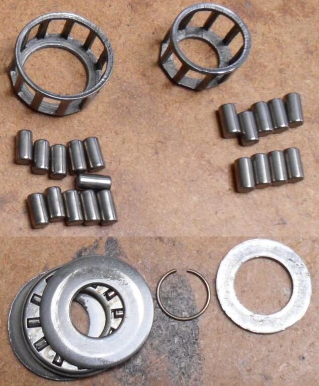
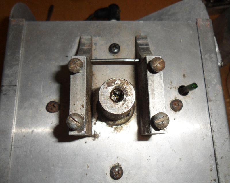
There are 18 rollers in both pictures I took, you have to fit them in the crankcase on this type before inserting the crankshaft. Can't see anything that looks like a thrust washer though.
Just to be really helpful (not) the parts lists describe that as a "crankcase assy. (includes bearing & thrust washer)" with no part numbers for the rollers or thrust washer, some parts lists from 1970 mention this type of bearing arrangement, I guess they could turn up randomly in other engines.
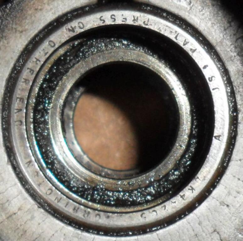
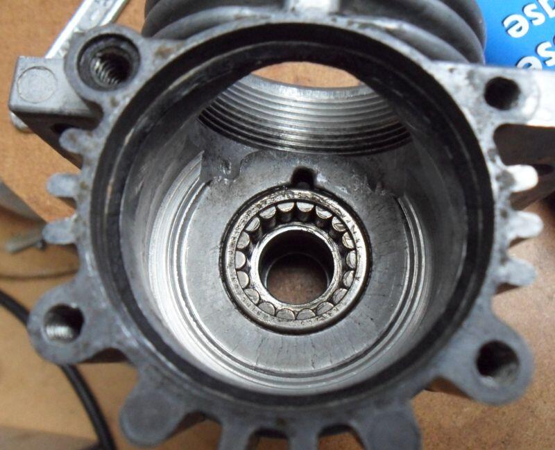
My picture was from a 13B-252 engine dating from 1973, here is the before picture, the bearing appears to be made by Torrington, I seem to remember something like a disintegrated seal behind it, also there is another parts crankcase I saw a few weeks ago with this bearing.
I’m thinking the gas tank probably doesn’t have anything special inside it so I’ll gently probe with a piece of wire and see if it will start to clear up. There is an original in-line fuel filter that is external to the tank and goes between the tank and the carb so I’m hoping there isn’t any full line or other filter inside the tank tube.
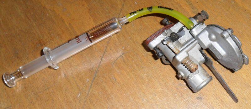
This is what I now use to clean the fuel tubing/filters in the tanks & carb, I have several different size glass syringes (the type that survives use with gas/petrol). I use gas/petrol or cleaner and use the syringe with a piece of fuel line to gently soak & push the crude out.
Note: this is best done outside & there is nothing in the syringe in the picture, I tend not to have the camera out when I'm cleaning with petrol.
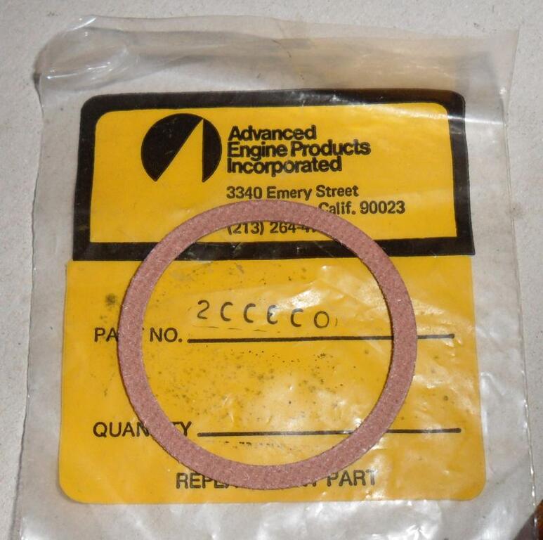
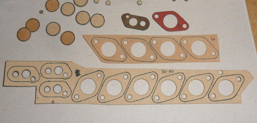
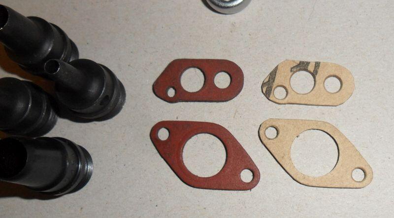
These are the red gaskets (#200600) I have, I believe the one used in these trimmers maybe slightly different (#200600B) as they only use one (don't know if it's thicker ), some of the later engines use two of the red gaskets (#200600A).
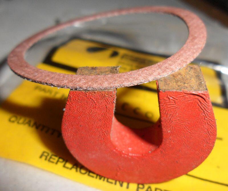
Anyway the part #200600 I have is approx 0.036" thick & does have steel wire used in it.
Good external lighting & the macro setting on your camera helps with close up pictures like that and editing to remove anything not of interest as the forum resizes images, resolution of small parts will be lost if you don't.
iPhone camera is all I have anymore... I’ll have to try editing sometime.
Sometimes I use either a torch (aka flashlight) or a desk light to get better lighting, the macro setting will probably be auto selected on your phone (a little flower symbol indicates it's on), I have an older digital camera where you have to manually select it. I find it's quicker to transfer pictures from the old camera to my PC (using it's SD card) then using my newer phone & it's painfully slow USB cable.
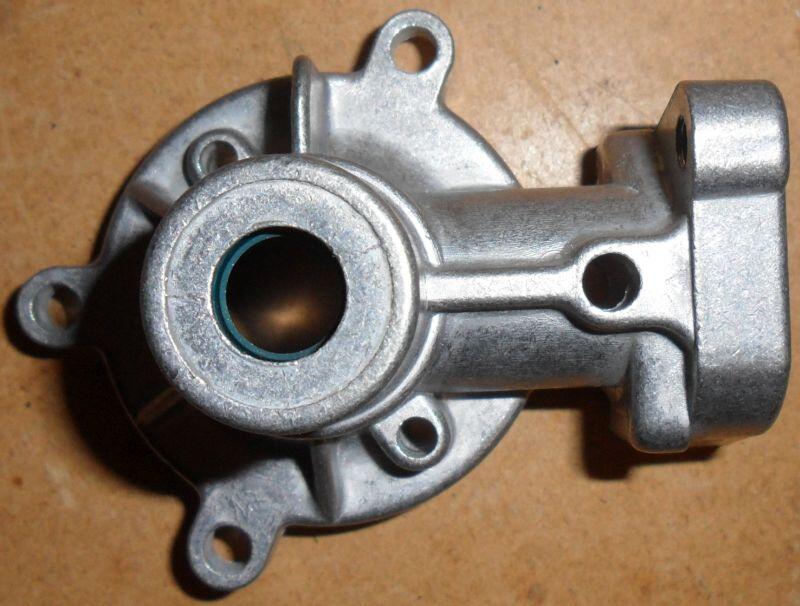
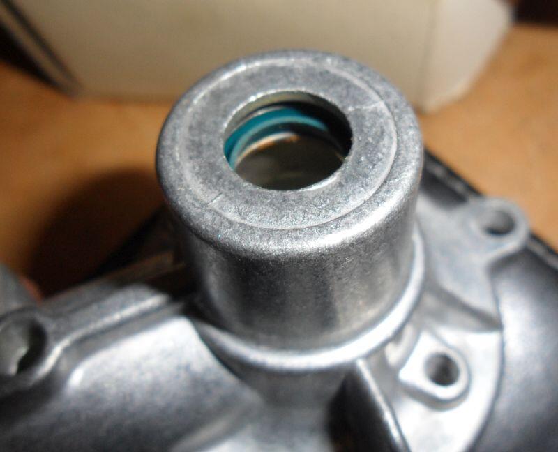
Better focus on the seal in this picture.
Inside with slightly pre-rusted bearing surface, all the NOS parts I have are like this.
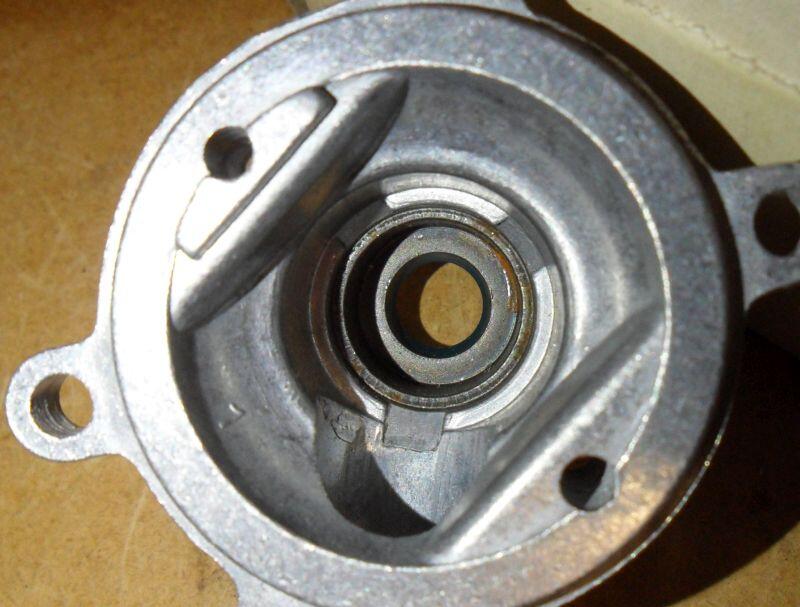
They aren't going to any use for the induction housing as it uses smaller seals for the PTO shaft, as far as I know they are bonded with a metal ring. But will help anyone that has a later engine that needs a new front bearing seal (flywheel side).
They probably changed to these non-replaceable parts so that they could sell the more expensive parts rather than just the seals.
Good external lighting & the macro setting on your camera helps with close up pictures like that and editing to remove anything not of interest as the forum resizes images, resolution of small parts will be lost if you don't.
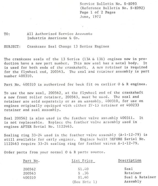
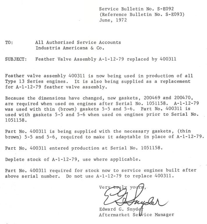
Here is the service bulletin that mentions the seal change, with the bit about channel locks pliers removed (terrible method of removing the retainer).
And the other service bulletin that mentions the type of feather valve with the none-replaceable seal (note; that the parts & part numbers are different to those used on the late production engine).
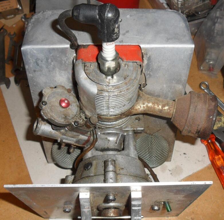
The front end of the induction case has a different type of seal than I’ve seen before. It appears to have a rigid metal core - and it doesn’t look like it can be removed without destroying it. It needs to be replaced but I don’t think I’ve seen any like this before.
I have mentioned these before, you may remember the some later engines having one fitted to the bearing cover behind the flywheel which is replaceable if you can find another, the others are the same but not replaceable as they are fitted behind pressed in parts.
From the shaft seals thread;
On 6/22/2019 at 11:27 PM, factory said:
The very late seals are attached to a steel ring, the flywheel side one can apparently be pressed out & replaced (if you could find replacements of course), but the reed valve one cannot be removed as the bearing ring in front of it prevents removal.
David
This is the seal in the induction case I used for my project, sadly I don't have any more of the induction casings, but do have a couple of the feather valves of the type used in this engine.
No idea, there are only two of these known to exist, probably just a filter, the valve is normally on the carb. I have a very very cheap borescope that could that could find out.
I checked on ebay.com, it wasn't showing GSP, they are pretty good at removing the option in restricted categories, but sometimes items get listed in the wrong category and the option does show, then the item can get seized.
Also items that are too big or heavy will never get shipped abroad.
Proper shipping companies have no problem with engines (drained of oil/fuel), chainsaws and radio valves.
Edit: they don't like magnetos either, my Dad lost a working 1920's Eisemann twin magneto to them.
ebay with their global shipping program, so it can go to most destinations worldwide.
I'm glad to see the global shipping is not showing on the listing, as they seized a similar generator one of the forum members had bought in the US. Engines & some engine parts are restricted items under the global shipping programme, as are other things like vacuum tubes/valves, they can either resell or dispose of restricted items.
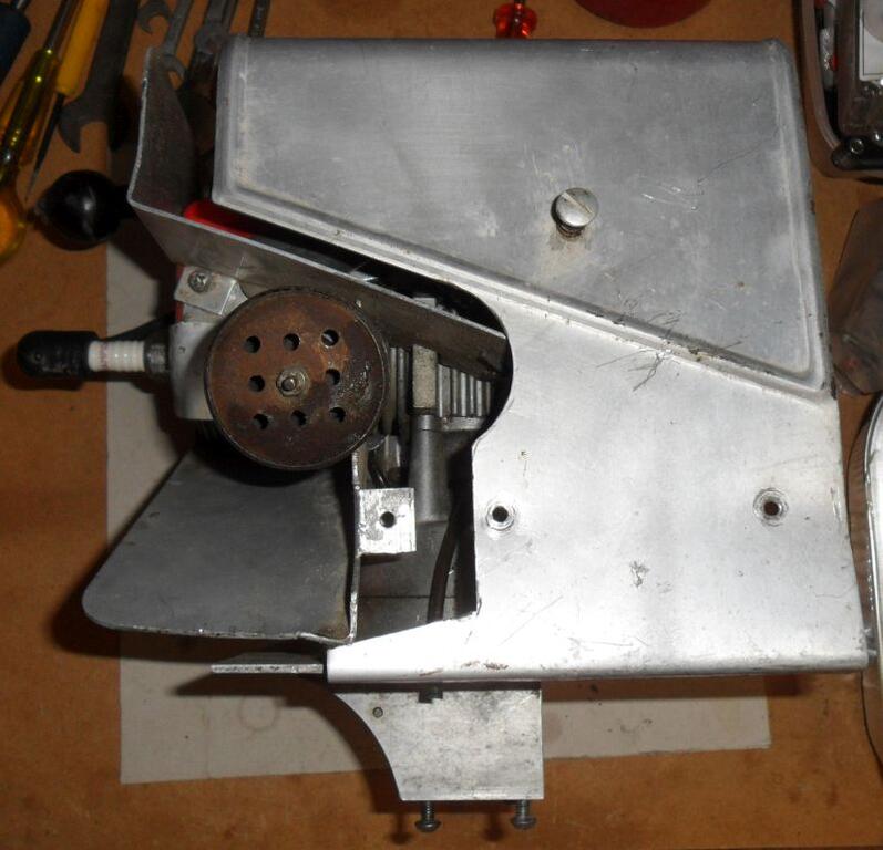
Hopefully not, I've taken lots of pictures during further disassembly to make sure I know where all the small parts go back.
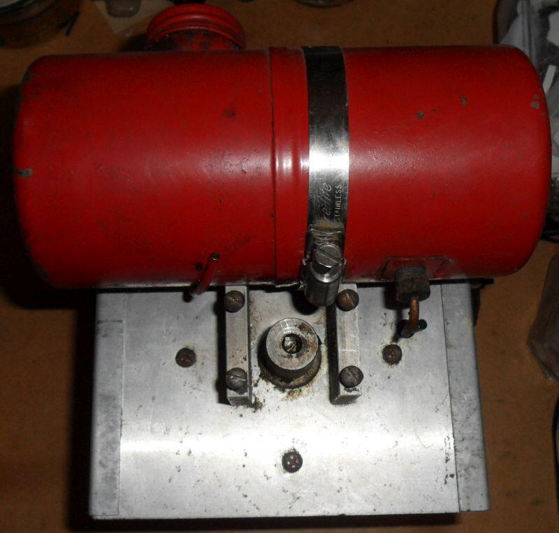
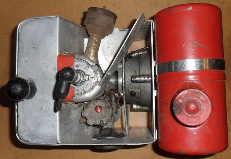
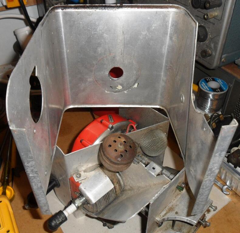
Here is the back of the powerhead with the coupling for the flexible drive, note this uses a larger than normal tank (the lid of this is currently seized on).
Might be hard to see, but there are two long screws holding the cover in place.
Those were removed along with the air cleaner, allowing the cover to be removed, the extension for the cylinder baffle plate is loose once the cover is removed.
Note the stop button on the side of the cover, it contacts with the standard brass stop strip.
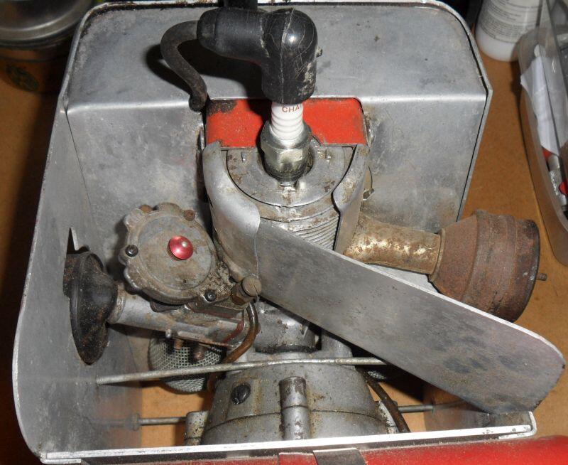
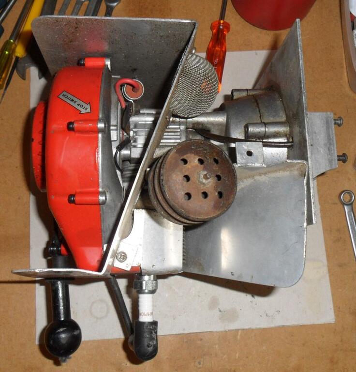
Possibly the only O&R where they had to build the engine up in the middle of the casing, don't know what they were thinking.
I won’t know until I can get the engine apart but it seems it might be missing a couple pieces on the exhaust collector. I don’t see the usual spacers or gaskets that sandwich the top and bottom of the collector.
These late engines are different, there is one thick spacer instead of the stack of thin spacers*, possibly a red gasket for the cylinder too, the induction section should use an O ring seal instead of the two gaskets.
Your spare engine should be the same.
David
*I don't have the thick spacer for my project so had to use the standard parts.
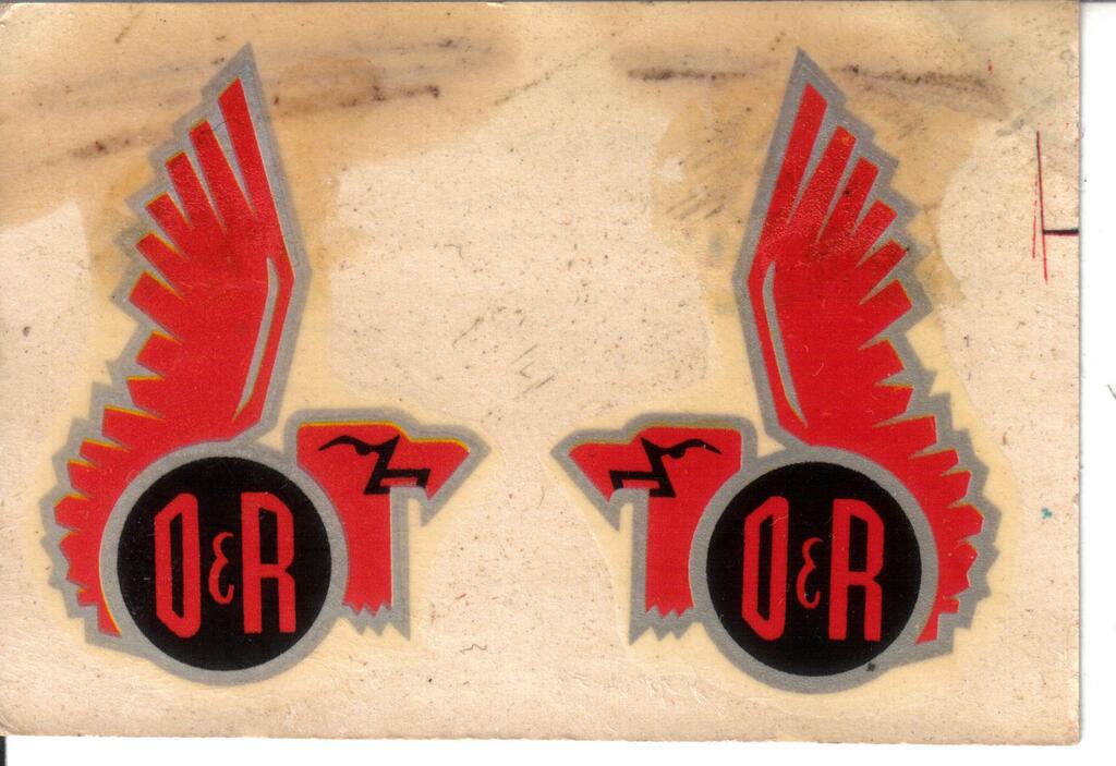
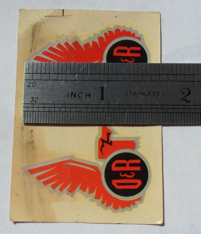
Here you go Paul, these original decals are 1½ inches tall, the scan could do with cleaning up if you're going to have some made, I can email you the original high-res scan if that helps.
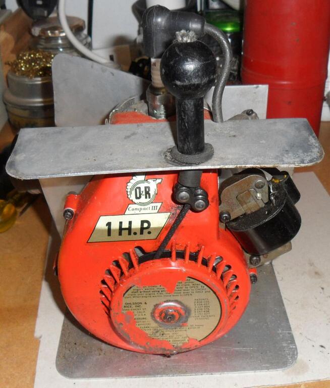
That looks in nice condition & you got the tank with it too, the .049 is known as the "Midjet" or "Mite". I have the water cooled "Mariner" version, it came with some original decals, I'll scan them & add them to the forum.
The .049 was the last model engine that O&R introduced before they stopped making them and brought out the Compact Industrial engine.
Good advise, I don't use the gasket punch kit very often and didn't at work much either (I used to repair train electronics, occasionally a new case seal or some custom mica insulators needed making).
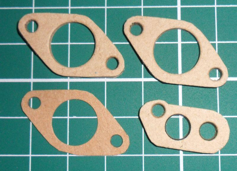
I've now made some more of the carb gaskets, without cutting them out before punching the holes. I was previously using a piece of chipboard that came in the packaging of a well known flatpack bookcase. I've now found another piece as the other one was rather worn out from punching cylinder & induction gaskets.
Here are some from the batch I have made, with a third sheet of thinner gasket paper to get the correct thickness to match the original pair of red gaskets used between the induction housing & carb. I haven't checked yet but the thinner one maybe similar to the single gasket used on the early O&R engines.
I wonder if it got used as a replacement engine for your fan
Curious why you think it may be a replacement engine vs original to the fan? The Industrial decal?
I don't have many or know much about the newer 13B engines as I prefer the older engines
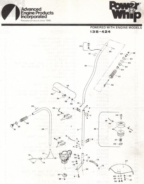
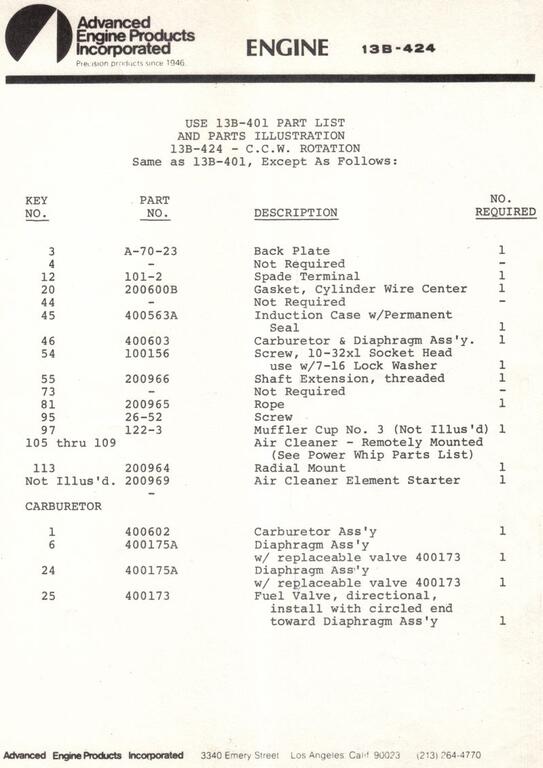
The parts list for the 13B-424 engine (that is stamped into the plate) gives parts that are not fitted to your fan i.e; the mounting plate, the remote air cleaner. The AEP decal does look correct for the date stamped into the cylinder plate.
It could be possible that the only the starter & cylinder plates are replacements, but the rest of the engine would probably show more signs of use if these had got damaged/lost & replaced.
You may notice the cylinder uses one thick spacer instead of the five pieces used on most engines, the induction assembly should also use the O ring instead of the two gaskets.
It looks like this engine model is CCW, that’s different from the average O&R isn’t it?
All the direct drive engines (3/4HP to 1HP) are CCW rotation, to change to CW rotation would require a different crankshaft (for timing), flywheel with dogs reversed and the starter rope & spring reversed (possible with 13B starter), apart from the starter these parts were never made. The larger Series 20A engine was available in both rotations.
Welcome, are you located in the US? If you are @CNew or @Wallfish should be able to help with a new carb diaphragm, the tank bracket & air cleaner will be harder to find as they are so often missing.
That is really odd, I had been using (loosely) the parts list for the type 13B-424 for my string trimmer/weed-wacker engine build, I wonder if it got used as a replacement engine for your fan.
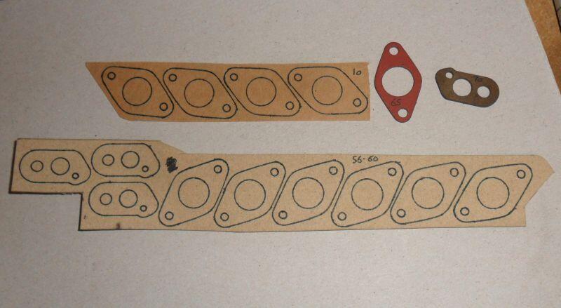
I've had a request for these, so I've had a go at making some using my gasket punch kit & a craft knife.
These are my first attempt with some of the cellulose fibre gasket material (slightly thinner than the original), I'm also a bit limited by the sizes of the punches for some of the holes.
I don't have any of the red gasket material, but I suspect it would split too easily when punching the holes due to the thin sections.


 ), some of the later engines use two of the red gaskets (#200600A).


 Engines & some engine parts are restricted items under the global shipping programme, as are other things like vacuum tubes/valves, they can either resell or dispose of restricted items.

 , is that a spindle you've found that fits the O&R?


Ohlsson & Rice: The Groomer Landscaper 600
in Ohlsson and Rice
Posted
There are 18 rollers in both pictures I took, you have to fit them in the crankcase on this type before inserting the crankshaft. Can't see anything that looks like a thrust washer though.
David