My handle comes from the coil side as well but they obviously could be switched. Not sure why
I thought that would be simply to figure out. ( some people are left handed)
It's shown fitted on both sides in the manual, I don't have any original combined manuals that cover the four Comet Tote'N Tools, there are two versions (still looking), the C/Saw did come with a manual that only covers the C/saw.
The other version of the Comet manual below was originally posted by @neons .
David
P.S. the only Comet tool I'm missing is still the chainsaw, OK I don't have the Comet drill but do have a much later Drillgine version.
Do you mean another company made an outboard attachment or are you referring to the Aquabug that R. Perry sold over here in the UK?
@CNew you do have the Polaris power head & attachments over in the US, probably just as hard to find as the Tarpen Mini engine power head is over here.
I've had one of those days where you go one step forward & two or three back.
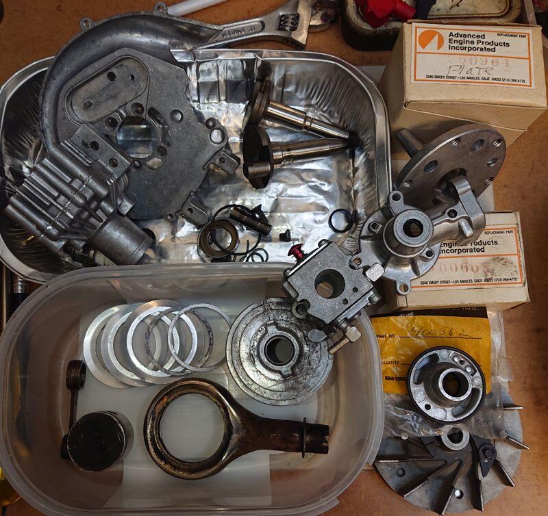
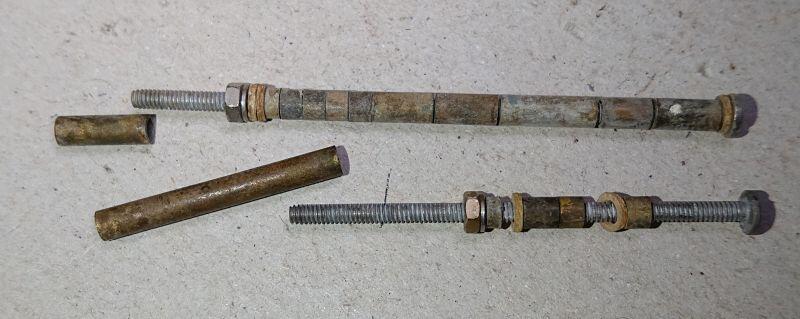
Here are most of the parts I had found for building this engine, the new parts are outside the trays on the right.
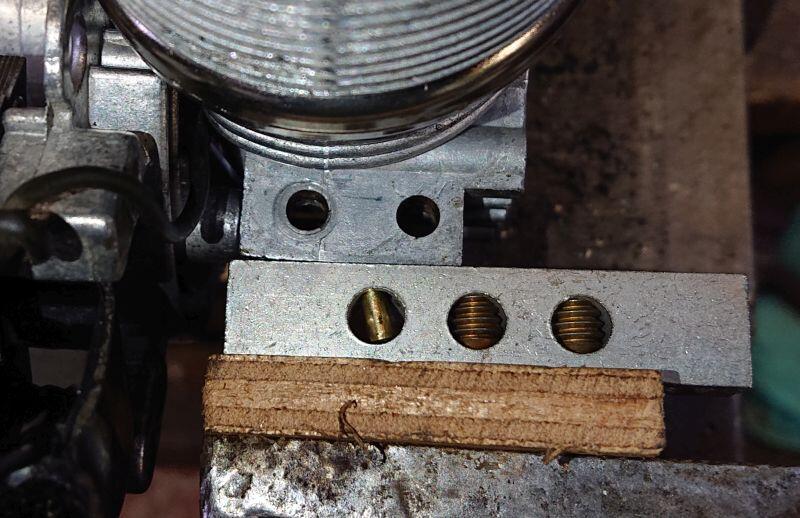
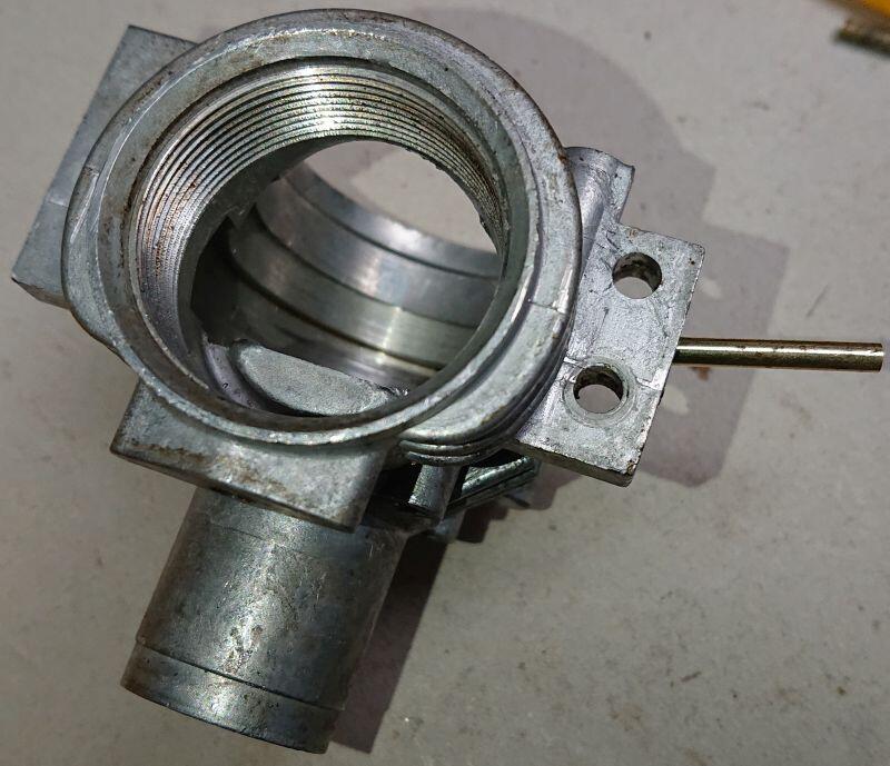
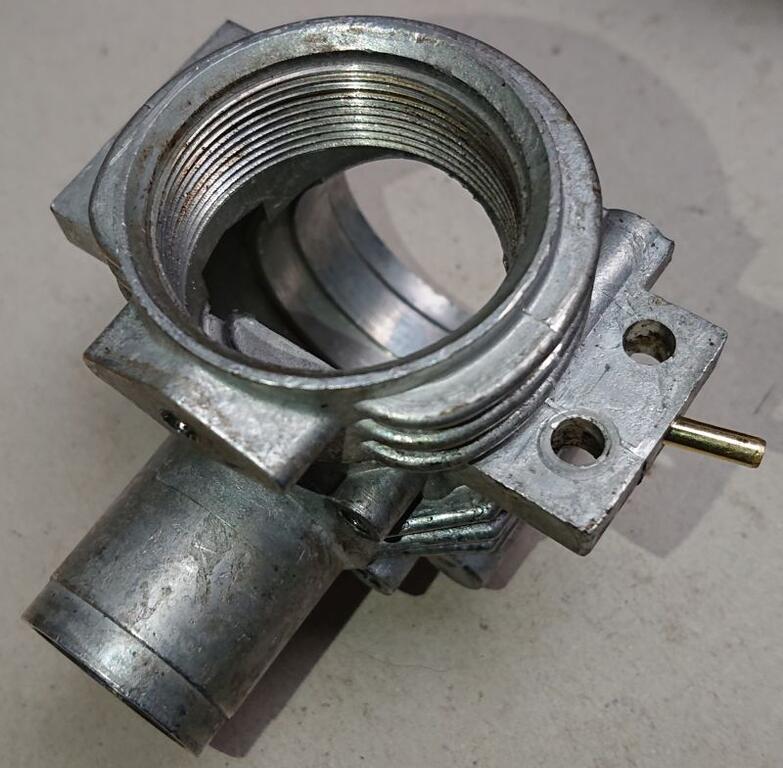
The crankcase was assembled with the crankshaft, con-rod, piston & magneto coil plate, then came the first problem, I would normally hold the crankcase in the vice when screwing the cylinder down, unfortunately the port tube in the crankcase mounting flange prevented me from using the pieces of wood I usually fit to prevent damage from the vice jaws.
A lot of searching for something else I could use found a brass earth terminal strip, removing one of the screws allowed the tube to be protected.
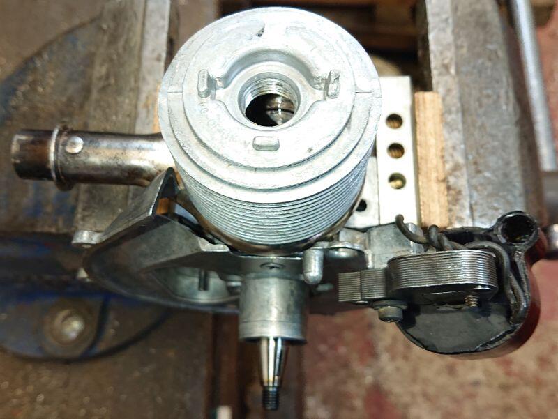
Here's where things went a bit wrong, I found I couldn't get the cylinder to screw down fully, I tried several times but it kept getting stuck part way. I then thought either the crankcase or cylinder might have damaged threads, I first tried the cylinder on another crankcase and it fitted fine.
The part built engine got stripped down again & I went through the other used cylinders I had, eventually I found one that fitted, ironically it was the one that originally came with the crankcase, I had picked another because the top fin had a piece broken off.
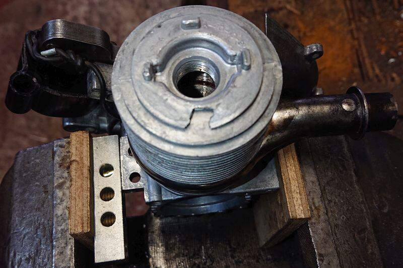
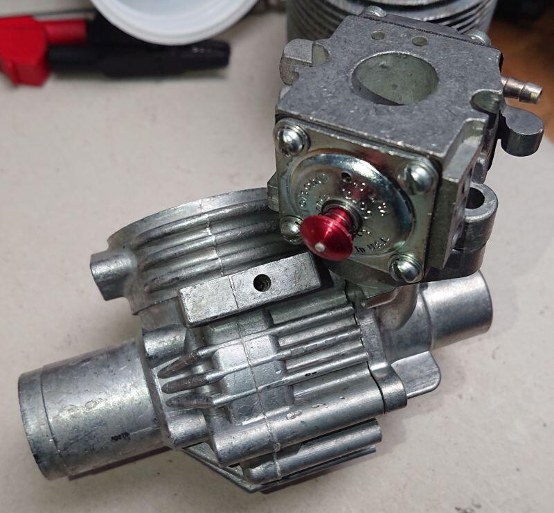
After this I needed to clean some of the parts again, it got reassembled to the point I was at before and this time thankfully the cylinder screwed all the way down with no problems. The exhaust collector was positioned at 90 degrees and I checked a starter would fit, this is as far as I've got today.
The Tarpen Flex attachments aren't too hard to find, apart from certain ones. Tarpen made PTO units to fit a lot of machinery that used the flexible drive to the attachments, the O&R engine & an electric power head are the only handheld versions.
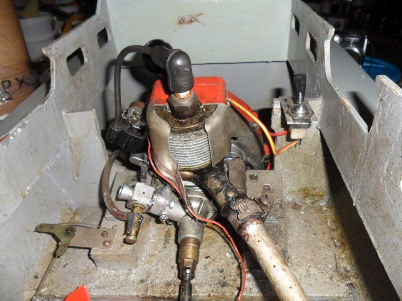
This is how I acquired the Tarpen O&R, it was in this Keil Kraft boat.
When I told the previous owner I was interested in O&R tools he said he still had some of the parts that were removed to put it in the boat, he originally bought it from a surplus shop (which had two of them) in the 1970's.
The only part it needs is a replacement clutch bearing assembly, if you have a look at the propshaft coupling you'll see the bronze bearing got brazed together along with part of the clutch. I'm also not 100% sure the clutch shoe assembly I fitted is correct but that was all I had.
You vultures might end up with a good score when I soon forget that I even collect O&R stuff, and then the O'lady puts it all up for sale.
Probably a high chance this vulture wouldn't be able to buy any of them, most sales of collections on ePay are always US only and the other vultures usually buy them all up before I see them.
My memory must be bad too, there is an early starter sitting on the shelf & I cant remember what it belongs too, it might end up on my Kenco pump if I don't' remember soon.
That would be very useful if you can remember, I've looked at lots of impellers and have so far been unable to find one of either the correct size or shaft fitting.
David
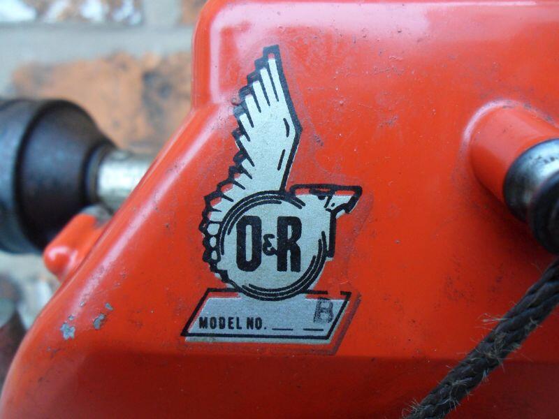
P.S. Odd that the engines are labelled B as that is supposed to be the standard engine supplied with an O&R base tank.
That's the second O&R pump Cnew has that's missing the pump section, I don't think mine has an intact impeller either, being made of rubber they dry out & crack up with age, as well as fail if run dry. I do have at least one pump with a good impeller here somewhere.
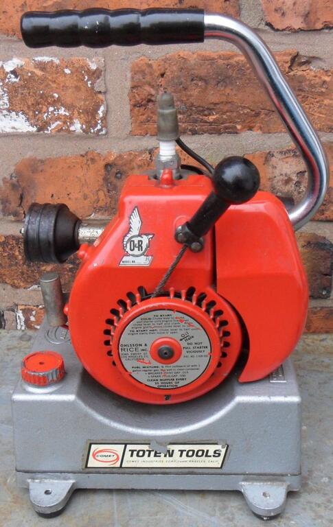
The handle is attached on the other side of mine, it's also one of the few older engines I have with the Model letter printed on the decal, I had to fit a new set of feet as the originals were falling apart;
I've come to the conclusion that these trimmers are quite on the rare side. There are probably very few left out of the production run. In the meantime, I'm still lookin'!
Your right, only one complete trimmer seems to have been found and there were three engines sold ePay from someone that acquired them when AEP closed down, they got re-sold by a trader on ePay & CNew bought one of them. The trader put an incorrect 13A starter on one of them too , did anyone buy that one?
They were made in the last few years of AEP, probably not many got sold* and hence little to do with these trimmers has survived.
*I would imagine most of them got put in the trash once AEP closed down & parts became unobtainable.
Only the parts shown in post #23 on the previous page, plus a few other unidentified spacers & fittings, I'm on the look out for used trimmer parts from other brands that may do for the trimmer head.
I've got most parts for the engine, apart from a series 13B type starter (may have to use one from another engine till I can find another), also need to repair another magneto coil.
Here is the crankcase after cleaning together with the NOS Tillotson carb & induction housing.
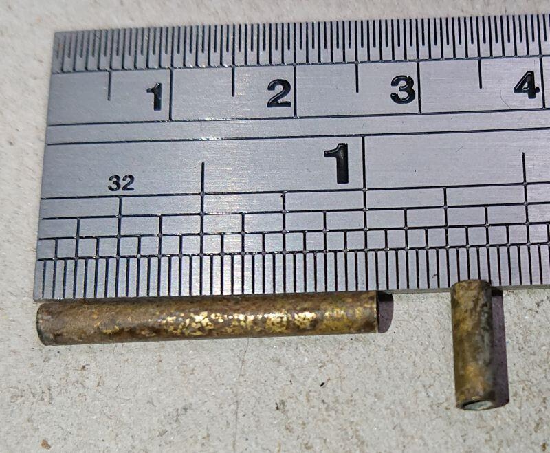
I found some brass tubing for the crankcase pulsation port, the tubing is from a scrap wafer switch (which had been drowned along the the item it came from), luckily it's a very close fit to the hole in the crankcase.
To fit the tubing I used a blowtorch to heat up crankcase to expand the hole & allow the tube (cold) to be pushed enough to for an interference fit once everything cooled down.
A cut-off wheel in the Dremel cut the tube down in size and the internal & external edges were de-burred, I had to clean the crankcase second time to remove oil & swarf.
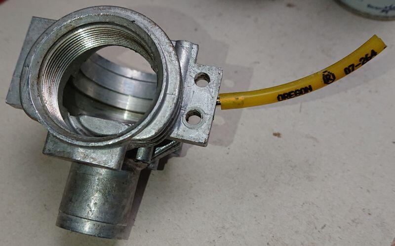
Fuel line fits perfect, need to order some more though.
Followed the guide above but used a piece of feeler gauge instead of floss. Everything slides right in. Held my breathe when the spring dropped down and hit the arm. Might attempt to make a spare spring out of the 0.003" feeler. Happy days!
It must have been a small pump something like that, probably taken apart & thrown out when the rubber impeller failed & it stopped working, there was a Comet pump sold recently with the pump missing too.
Thank you for all the helpful suggestions. I think I’m tracking with the ideas but additional photos are always helpful.
I took some pictures earlier today to show the technique I use to join the wires & leads of the diodes together, I'll get them edited & uploaded tomorrow as it's quite late now.
David
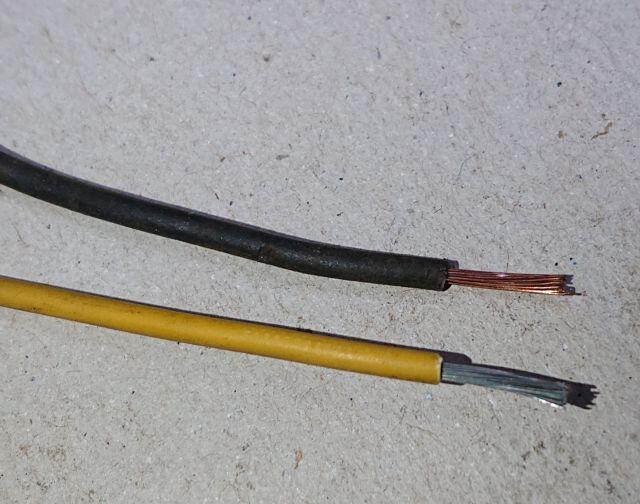
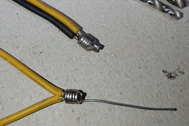
Here is how I made the join for the wiring in my TT, demonstrated with wire from a scrap wiring loom, the technique used for the wire loops dates back a very long time, I first saw it used in a pre-war radio for joining multiple wires & components together (before printed circuit boards existed).
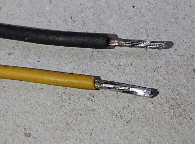
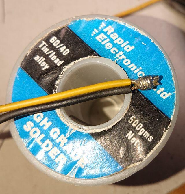
The wires before & after tinning with fresh tin/lead solder (note: do not tin wires if using crimp or wire-nut connections).
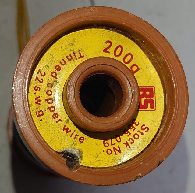
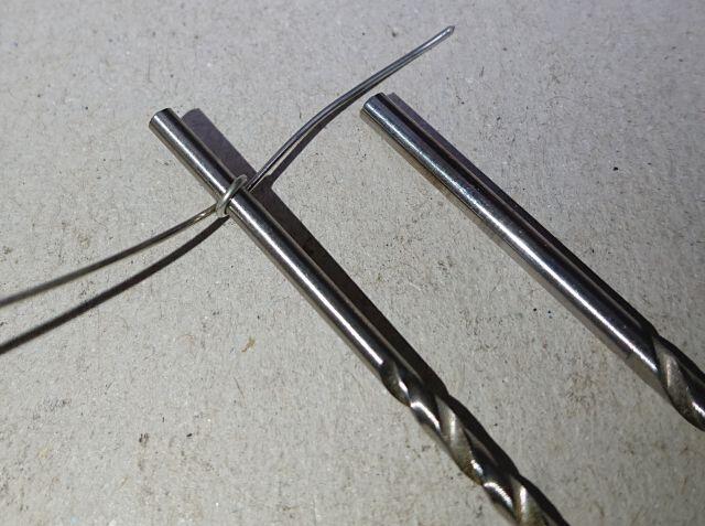
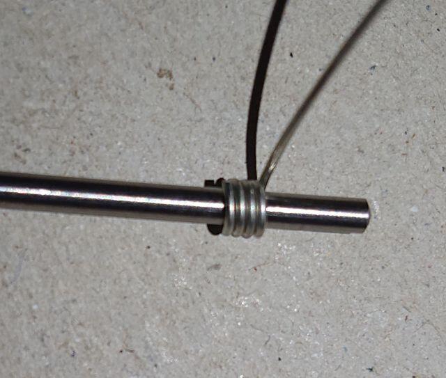
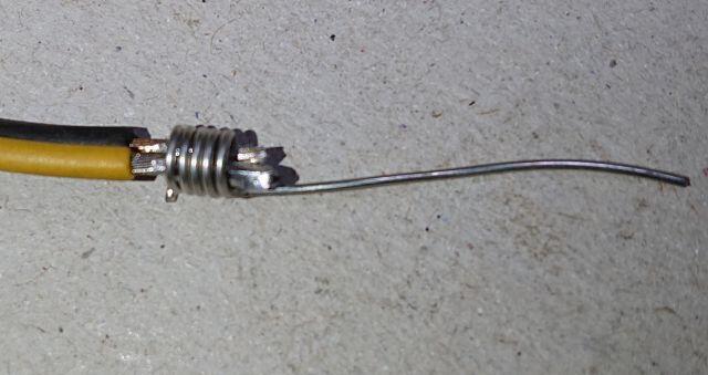
To make the loops I use standard tinned copper wire (aka fuse wire), I have a few different wire gauges for joining different thickness cables, choose a drill bit or something else that is a bit larger than the cables to be joined, wrap a few turns of the tinned copper wire around & cut to length.
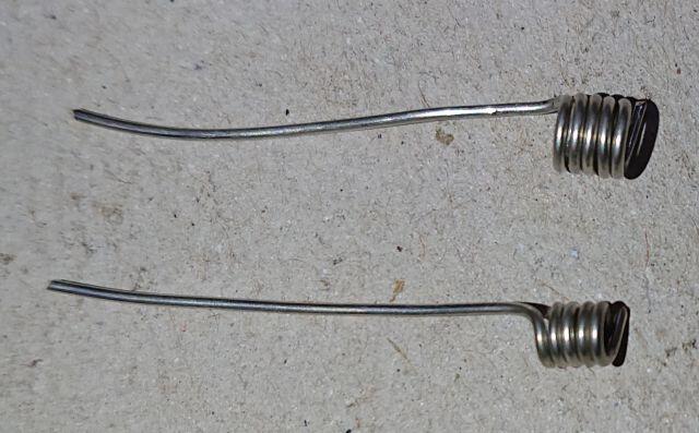
I've shown a couple of sizes I made and if you leave a length a wire as shown they can be used in other things for extending component leads. Slide the loop over the tinned wires to be joined (for a continuous length of wire slide the sleeving on before soldering).
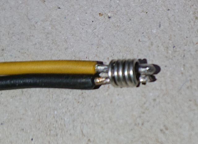
The whole lot soldered together with tin/lead solder and here are some finished joins ready for sleeving.
Thank you for all the helpful suggestions. I think I’m tracking with the ideas but additional photos are always helpful.
I took some pictures earlier today to show the technique I use to join the wires & leads of the diodes together, I'll get them edited & uploaded tomorrow as it's quite late now.
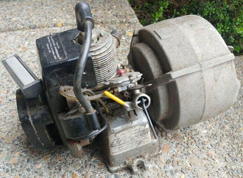
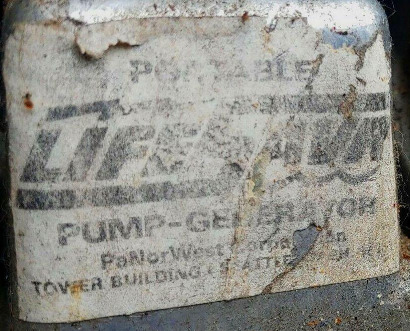
A very similar unit was called a Life-Sav-r and had a water pump that connected to it as well. I don't know the exact particulars because I don't have one.
One of the LIFESAVR branded versions of this generator just sold on ePay, sadly missing the pump, but you can see how it would attach, an extra bracket is fitted to the generator housing & the plastic cover removed for fitting the pump to the alternator shaft.
I'll move the others later tonight, I've sent you my email address for any other manuals you would like adding to the forum, thank you for taking the time to scan them.
Edit: All six Octura brochures are now in Section 4 of the Manuals/Brochures thread;
I came up with the date of 1967 from a operation instruction sheet that came with it. Issued date of 1967 Revised date of 1971.
That is indeed just the year of the last change to the instructions, at the time your engine was made. The serial number confirms the date of production of the engine as being Jan 1975, 13B is the series of engine & 352 is the engine spec.
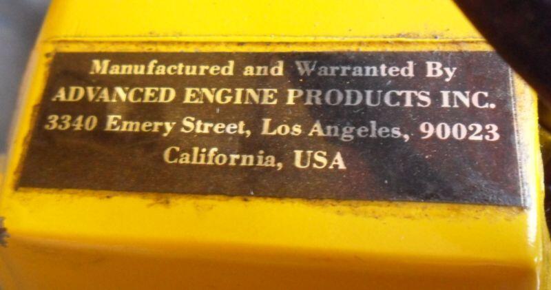
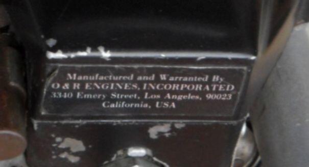
It's interesting to see it's branded O&R, the first adverts with the new name of Advanced Engine Products Inc. (AEP) appeared in Dec 1974, it looks like the factory carried on using up parts with the old brand first.
Also, it looks like there is a rusty red paint coating on the copper wiring on your coils - did you add that or was it original to your unit? Mine isn’t just bare exposed copper.
That's how it was when I bought it, it could be pigmented varnish similar to what we used at work for traction motors, but is probably just lower cost red paint. Rather annoyingly they painted over the wire colours, but this isn't too much of a problem as measuring the resistance confirms which windings are which.
Yours just has lacquer on the coil wire, but it does allow you to see the sleeved connections to the coils better.
17 hours ago, CNew said:
Looks like mine may have been store in a humid environment, the wires that are severely cracked also have blue-green corrosion permeating the entire wire.
The corrosion of the copper is due to chemical reaction to the rubber insulation, copper wire used is normally tinned to prevent this, nothing else on your TT looks rusty/corroded. If you look at mine the socket clamp & diodes were very rusty.
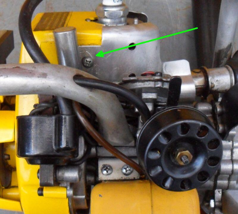
The condenser body needs to be grounded and it's loose in the pic.
It might be screwed down to the crankcase flange which would still work, the wire looks quite short, the later tools often have it mounted on the the cylinder cooling baffle/plate above the coil, needs a longer wire for that though.
13 minutes ago, Wallfish said:
The black label on the top of the blower is an Advanced Engine Products label
I think it is too because of the engine date, but can't confirm the label says that as it's not clear.
BTW there are black labels for both O&R & AEP branded engines.
These are a little tricky to work on, they come apart & go back together in a certain order, I'm still looking for a manual to add to the forum.
It's quite a bit newer than 1967, engine SN 501xxxx was built in Jan 1975, also the engines weren't called the series 13A or 13B till Sept 1970, does the label on the top of the starter say Ohlsson & Rice or Advanced Engine Products Inc? I reckon it could be the latter.
The later carbs have a brass check valve which often gets stuck with old dried out fuel mix, also they can have the rubber seal for the arm inside the diaphragm assembly, these also go bad. The diaphragm will need changing if it's hard & brittle.
The intermittent spark could be the points needing cleaning or a loose/bad connection somewhere.
David
P.S. nice to see one of these drills that still has the chuck key with it.
Those wire nuts aren't used much in the UK and the crimps originally used would need expensive tooling for a reliable connection.
I'm not sure if it shows in the picture, but I make a ring out of solid tinned copper wire to use for the soldered connections, then put the wires in this before soldering, it helps make a much stronger connection, I can take some pictures if needed.
Also they may be a pain to solder if you don't clean the tarnish from the wire ends before soldering.
Two layers of slightly larger heat-shrink sleeving cover the join, use a longer piece for the first layer & fold it back on itself back before sliding the second piece on and this will cover the exposed end.


Ohlsson & Rice: Comet Pump
in Ohlsson and Rice
Posted
It's shown fitted on both sides in the manual, I don't have any original combined manuals that cover the four Comet Tote'N Tools, there are two versions (still looking), the C/Saw did come with a manual that only covers the C/saw.
The other version of the Comet manual below was originally posted by @neons .
David
P.S. the only Comet tool I'm missing is still the chainsaw, OK I don't have the Comet drill but do have a much later Drillgine version.