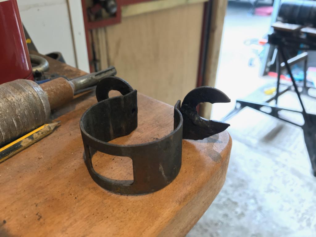
A while back I noticed a few people asking about these hitches on a Facebook page, thought I’d have a go at making some to see if I could sell any. Here’s how far I’ve got.
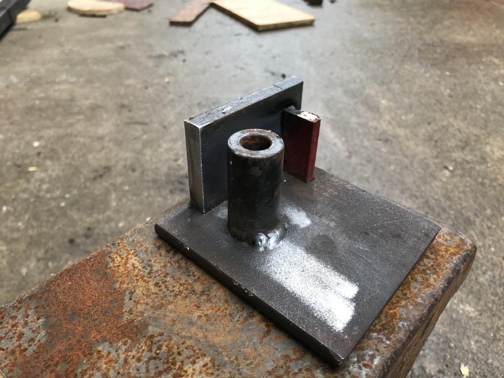
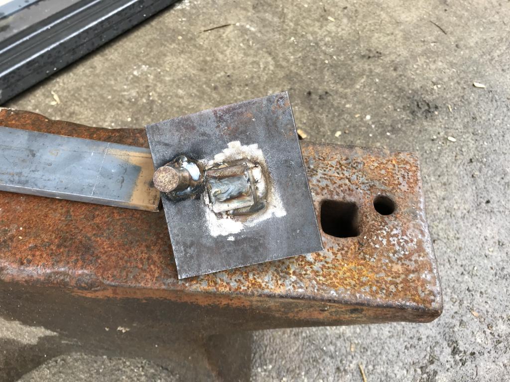
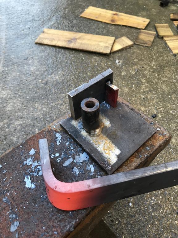
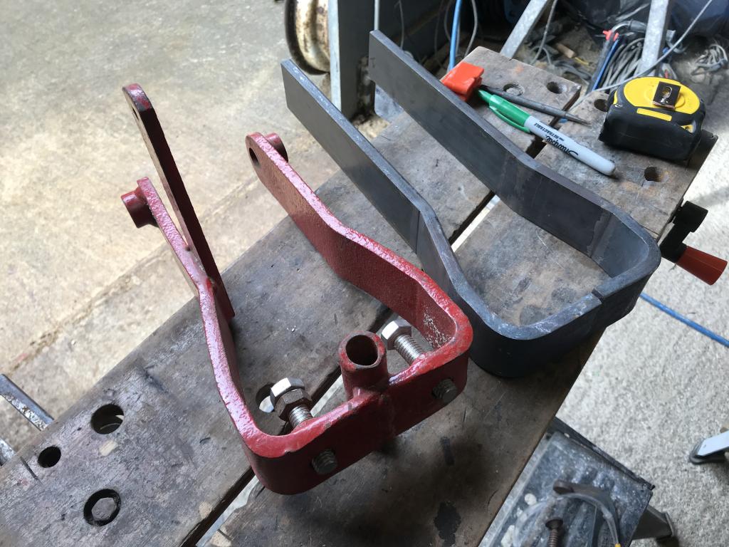
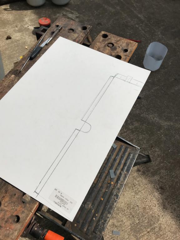
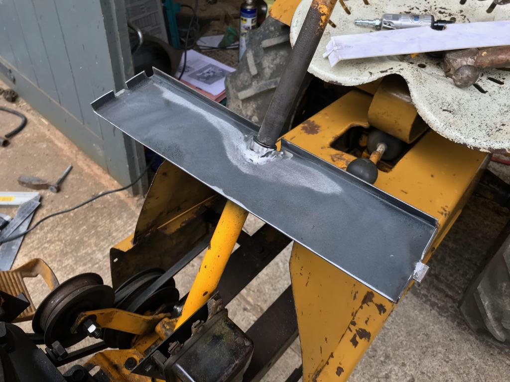
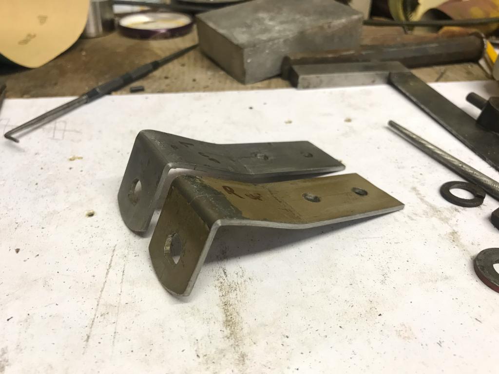
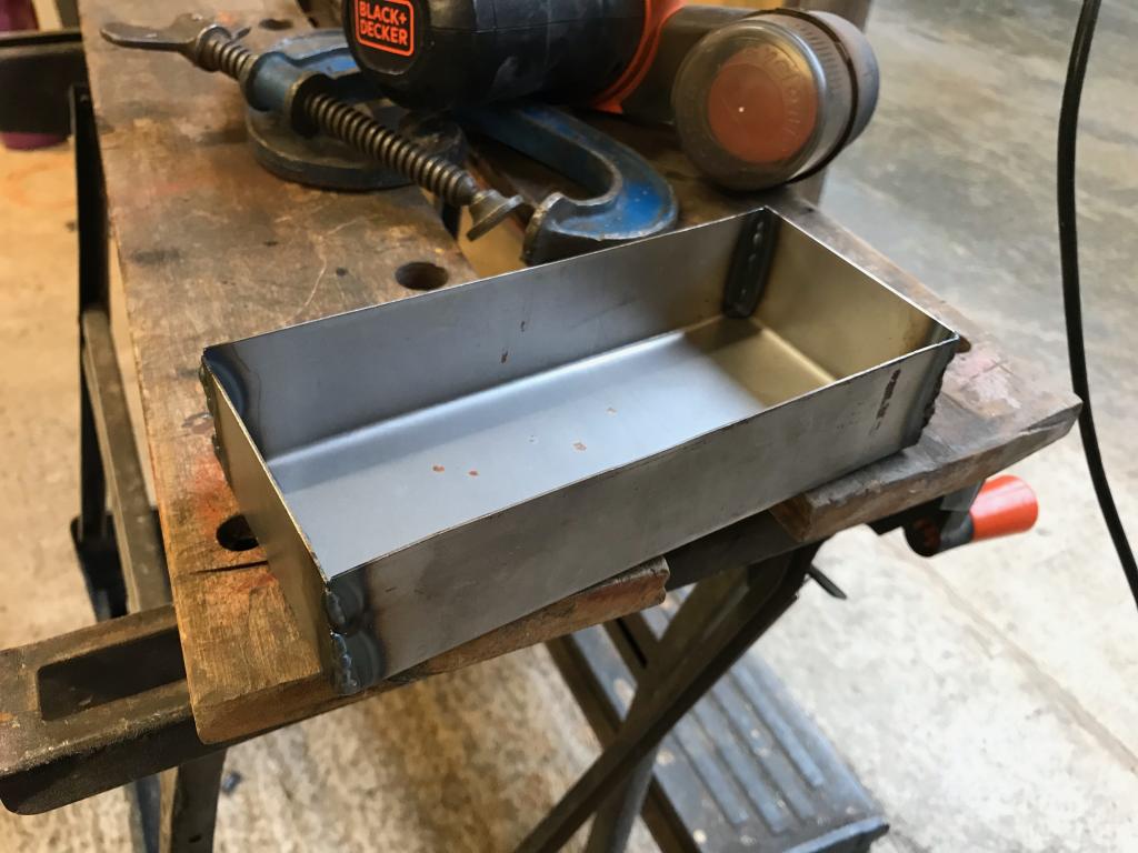
First job was making a jig to put the 90 degree bend in some 10x50mm bar.
needed some 1” square bar to fit in the hardy hole of my anvil.
This is the jig I made
The round bar fits in the pritchel hole to keep it sturdy
Works a treat
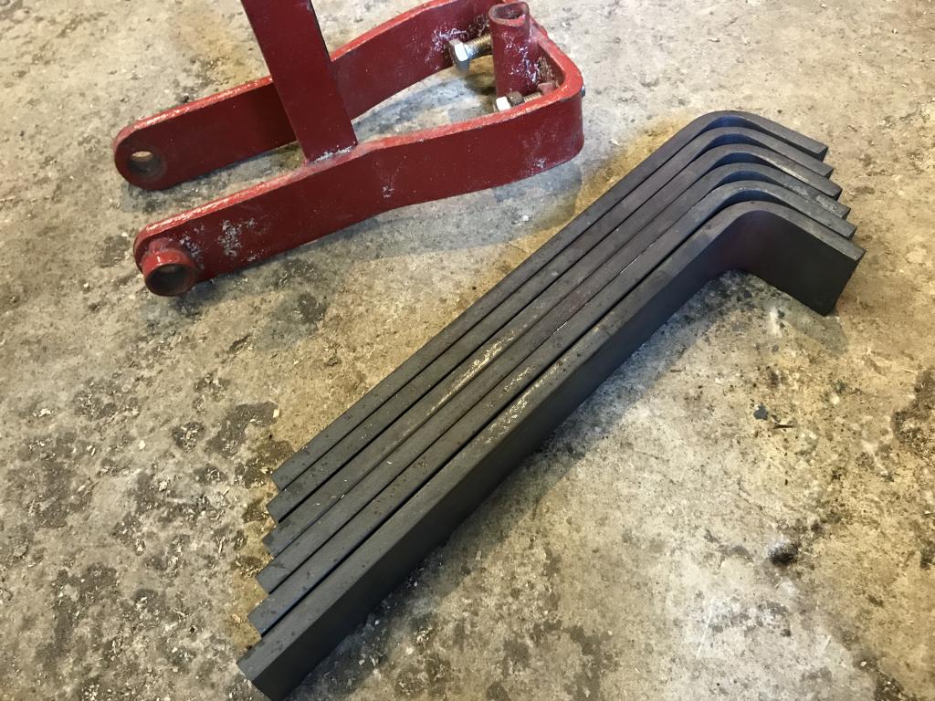
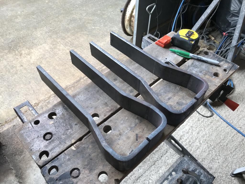
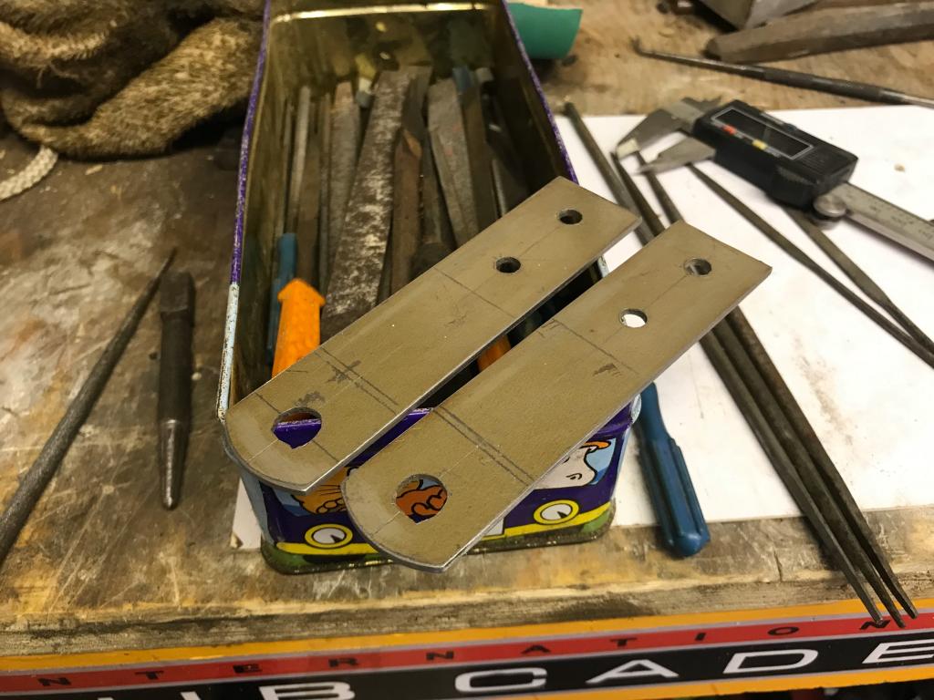
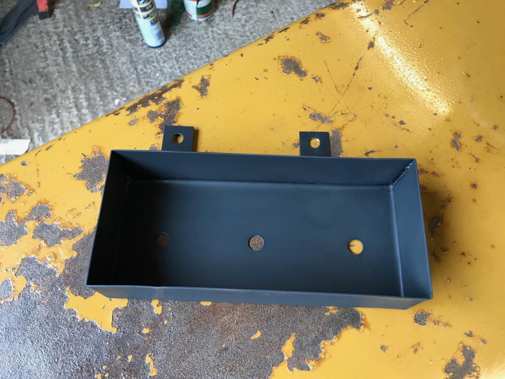
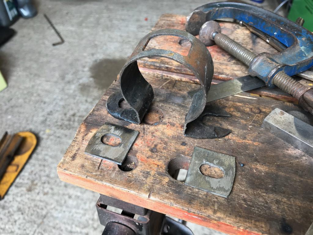
All the same
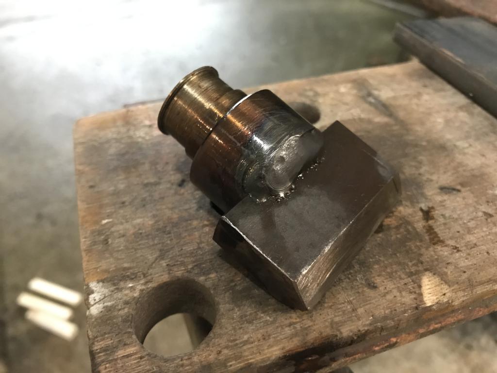
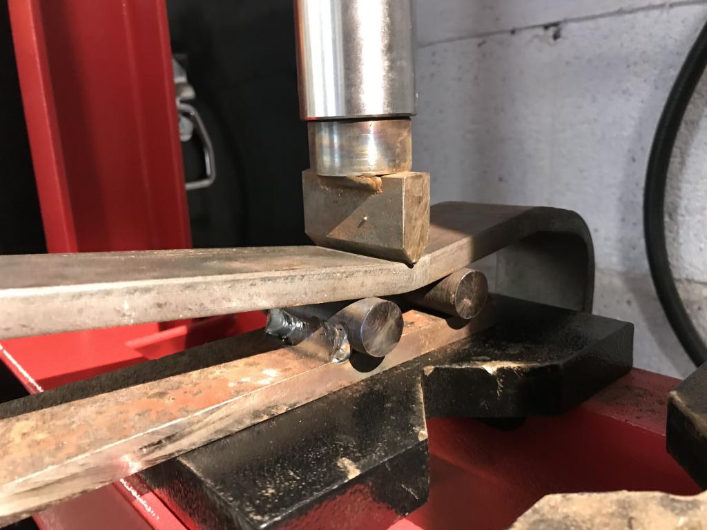
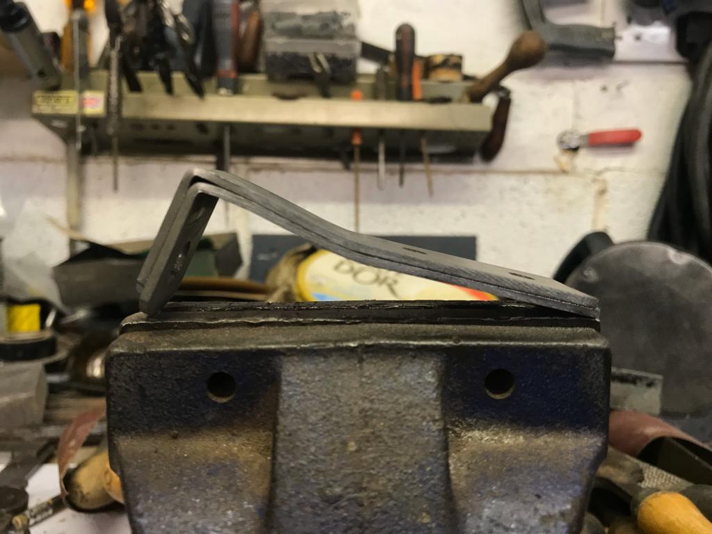
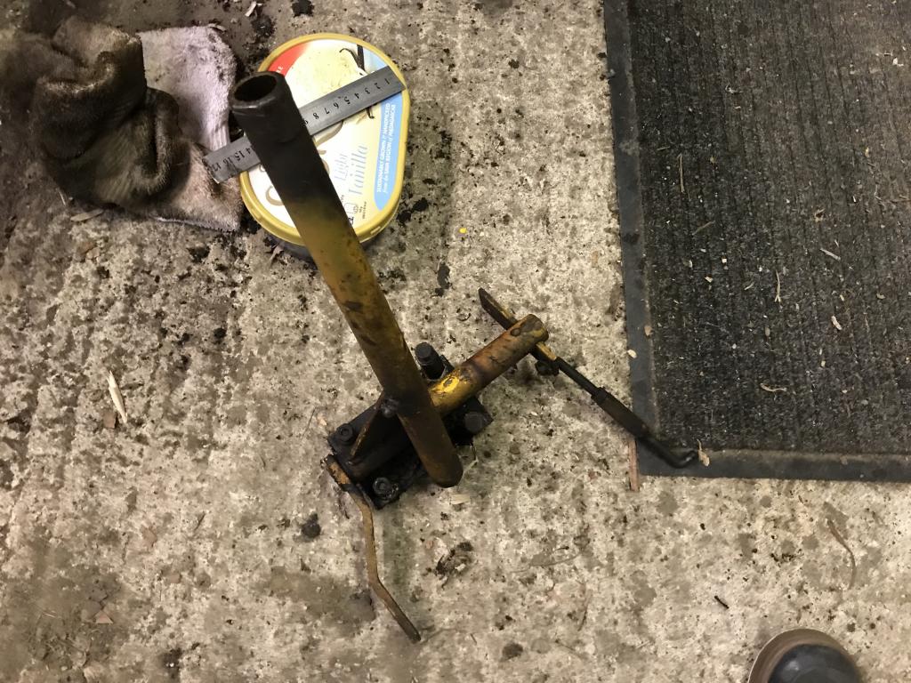
Next hurdle was putting the cranks in the bars, I made up an attachment for our hydraulic press
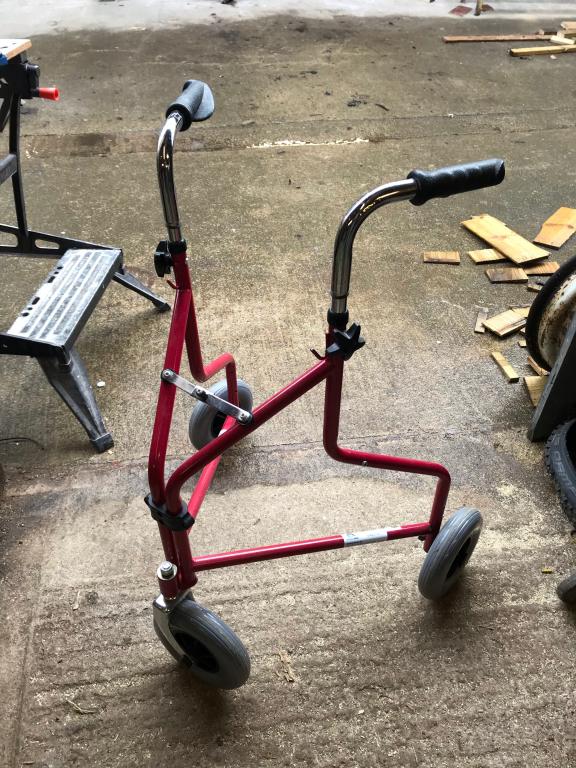
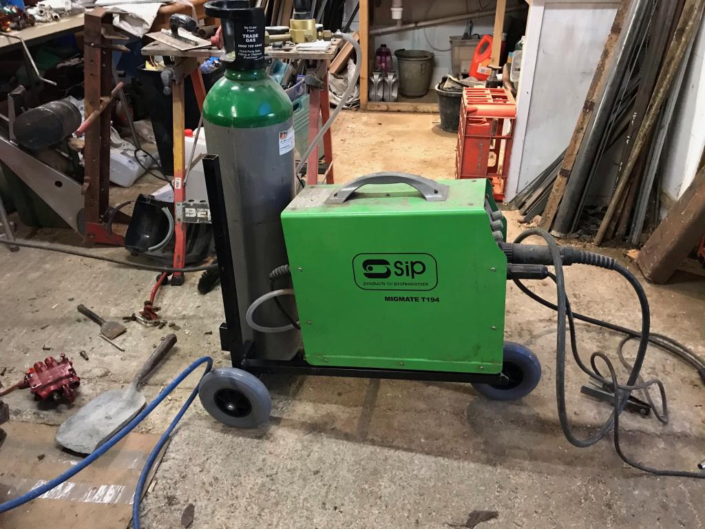
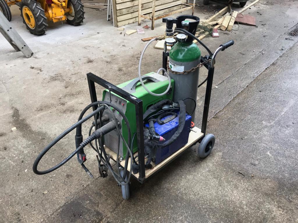
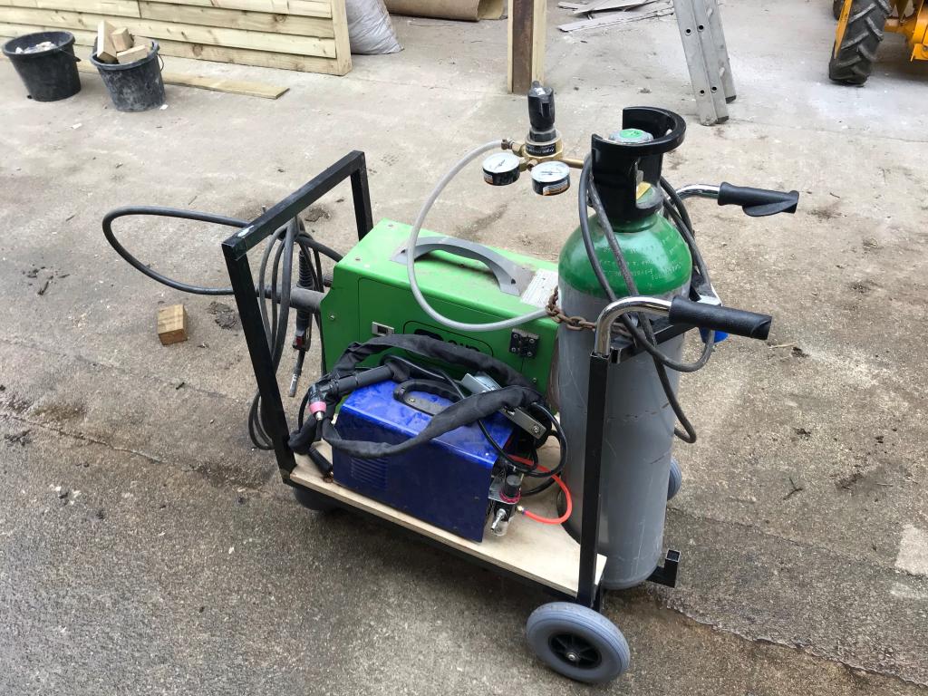
Quick little fabrication project. I repurposed this 3 wheeled walker thing that my grandad got his brother as a joke present .
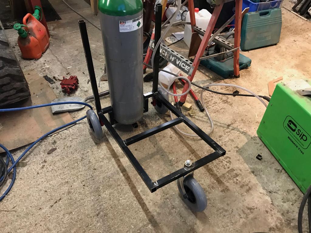
I didn't use any of the original tubing as it was quicker to use square stuff we already had.
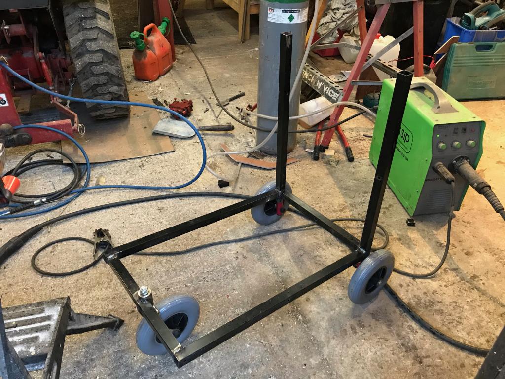
The bottle sits low down over the back wheels for stability.
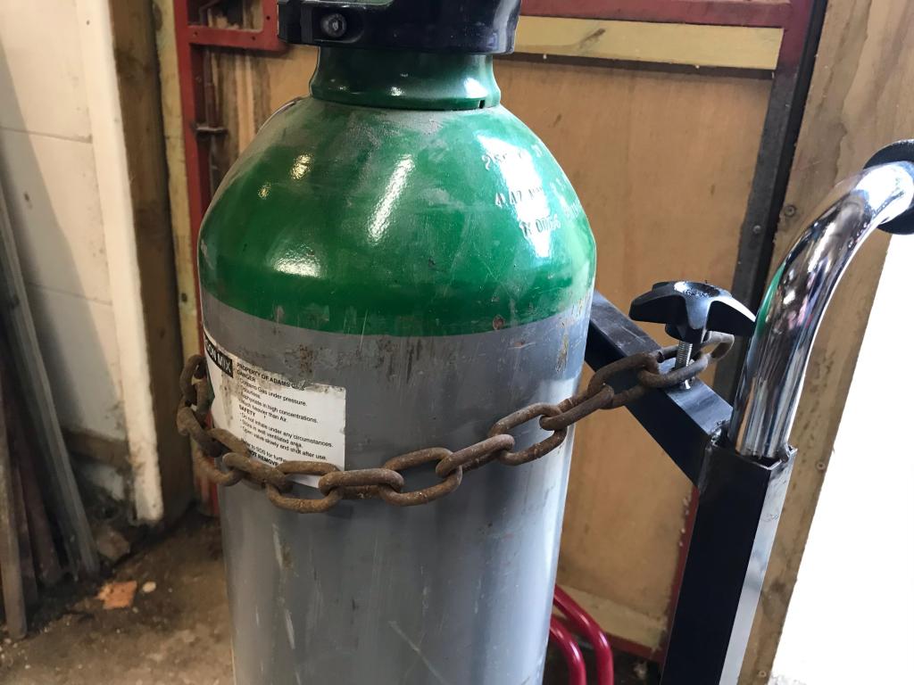
The old adjustment knobs were used to attach the chain, works well.
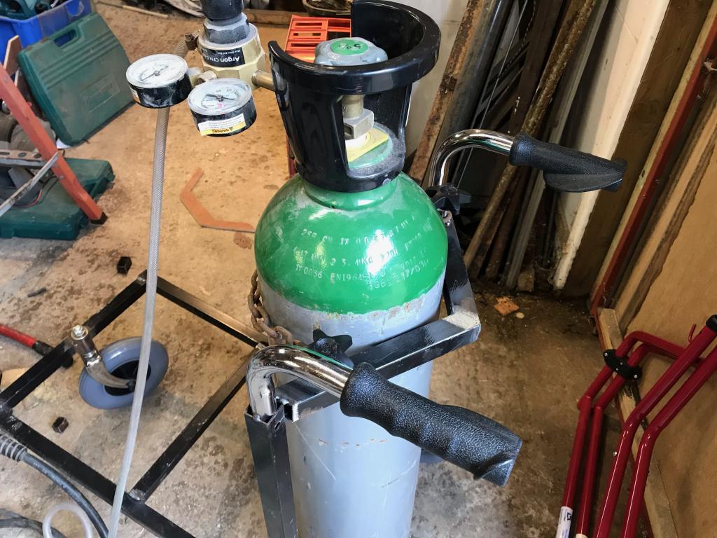
For the novelty factor I used the handles makes it easy to push around.
All finished, its proved very useful so fair when moving it between workshops! I might add some bars on the sides later to hold the welder and plasma cutter on properly. Works well enough without them though
Well i've looked high and low and I can't find it anywhere. I'm normally pretty good at remembering where parts are and I can't recall seeing one since before we moved 5 years ago
We had one on a lawn ranger engine that blew up, just looked in the box full of the broken parts but can't find it, we may have sold it. Will have another look tomorrow.
Finally worked out why my pictures wouldn't upload, stupid phone now takes photos in an unsupported format (by this website), managed to change it so here we are.
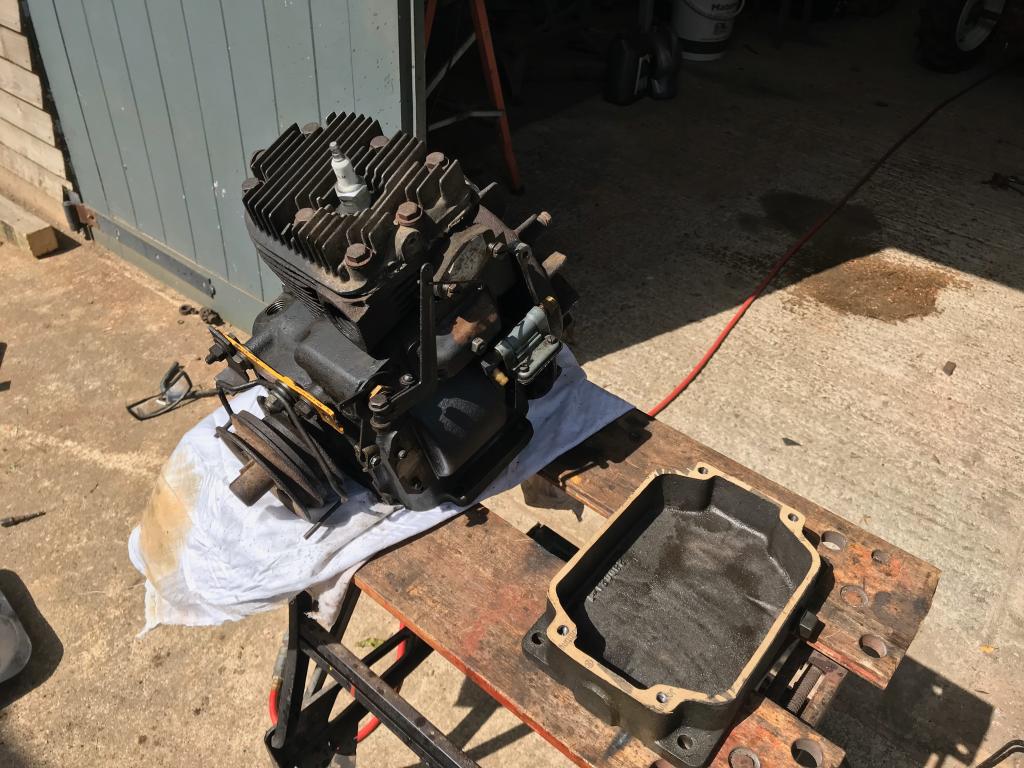
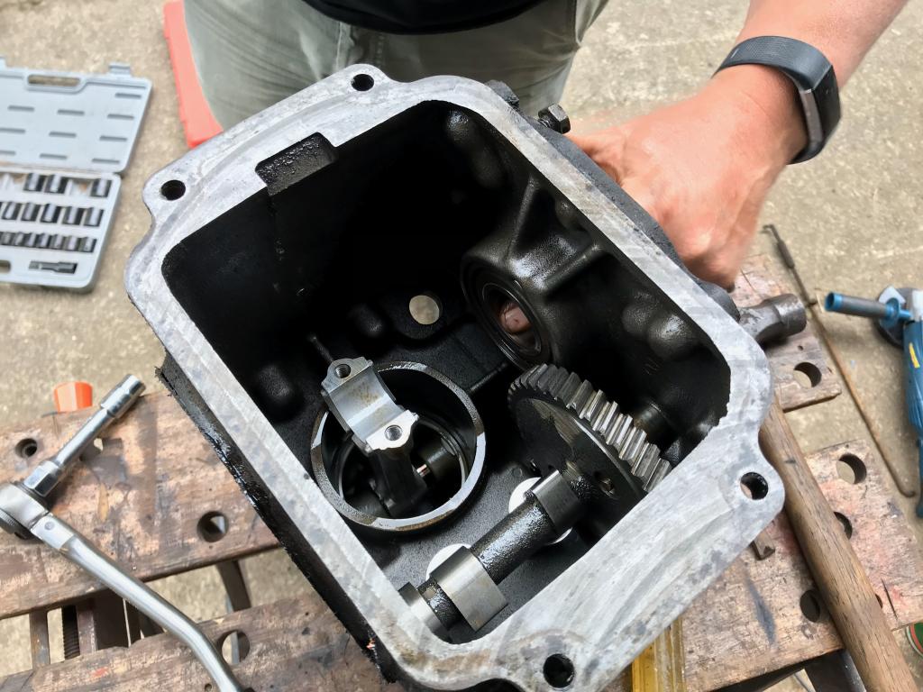
new sump gasket made
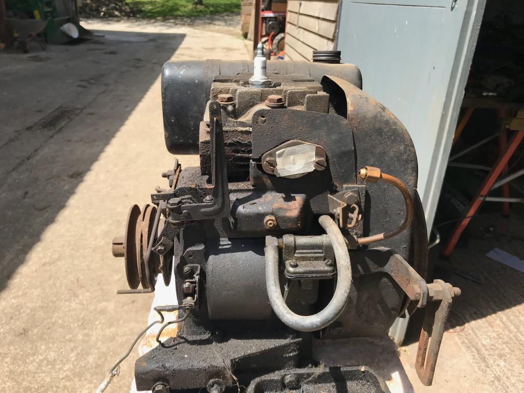
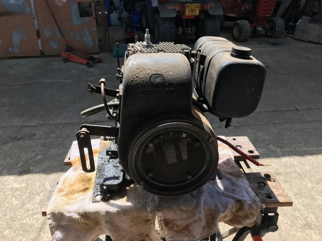
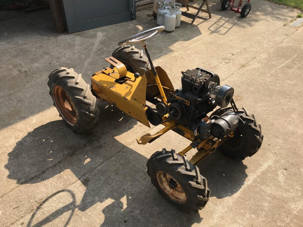
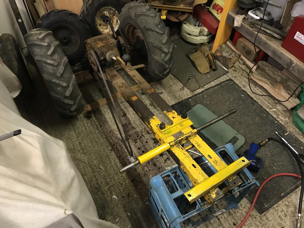
Once stripped down, it was time to give the whole tractor a bit of a clean up ready to put back together.
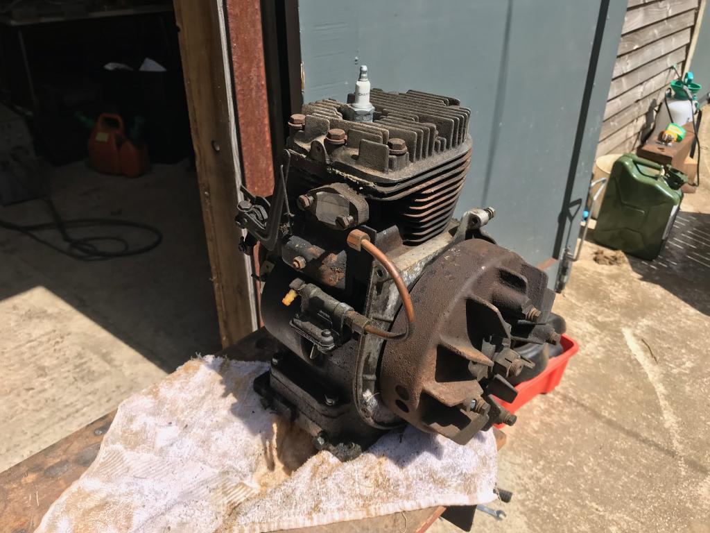
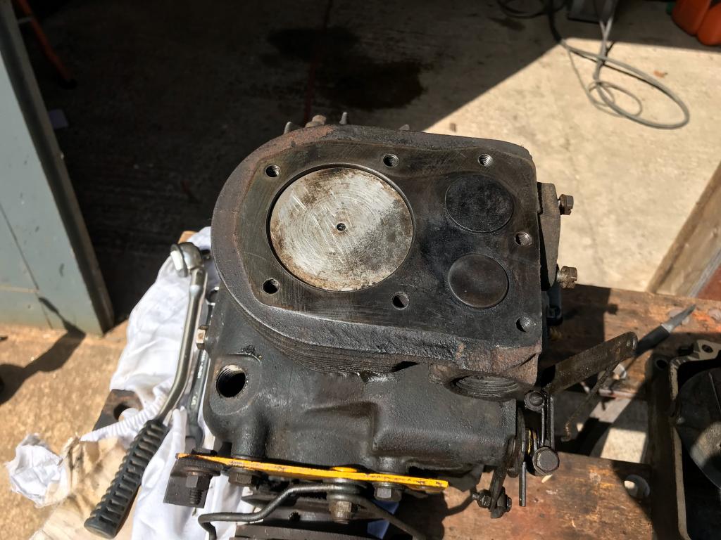
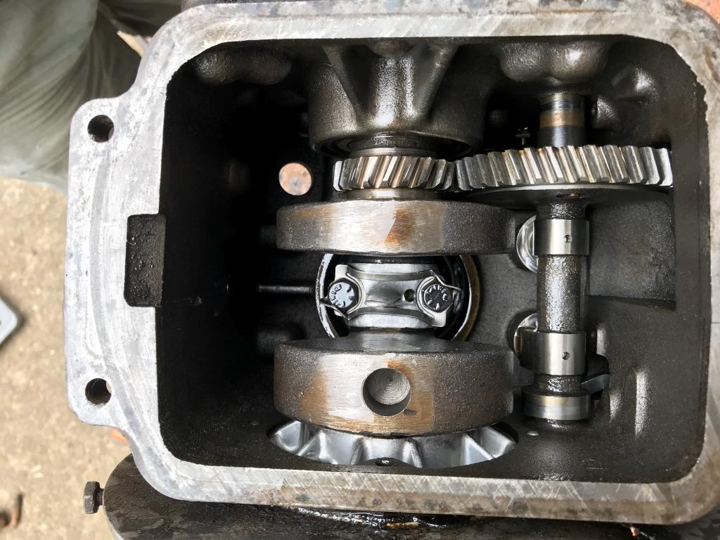
The crankshaft bearings were jiggered so the engine was stripped down.
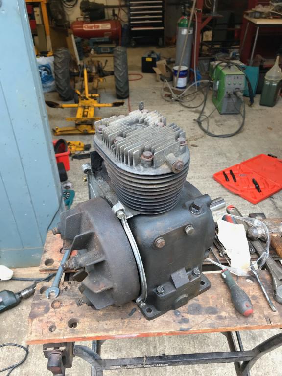
Back together and already sounding better.
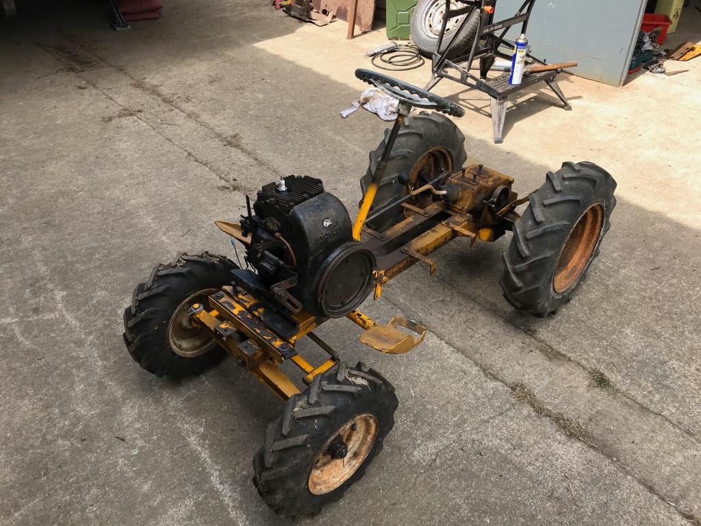
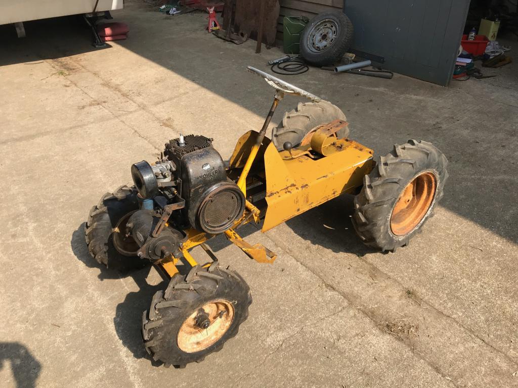
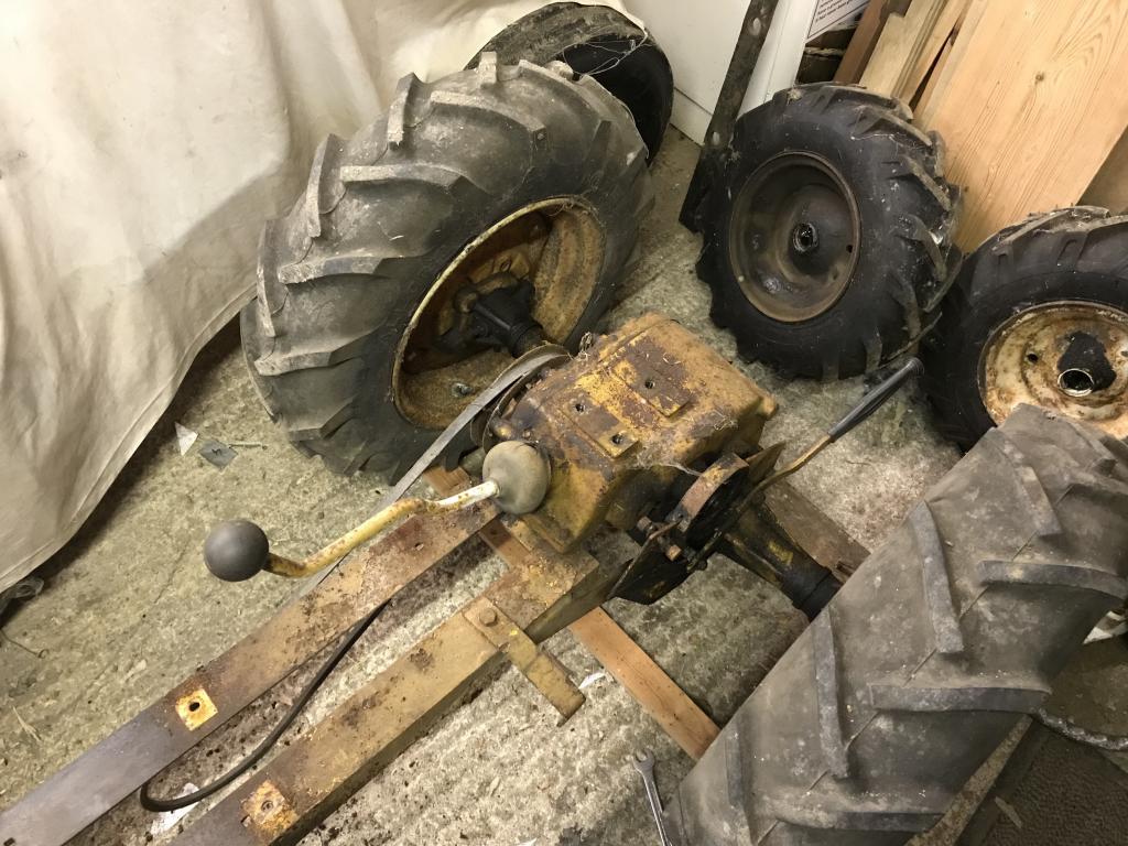
Back on 4 wheels, i'm yet to clean the wheels up but i'll get round to it one day.
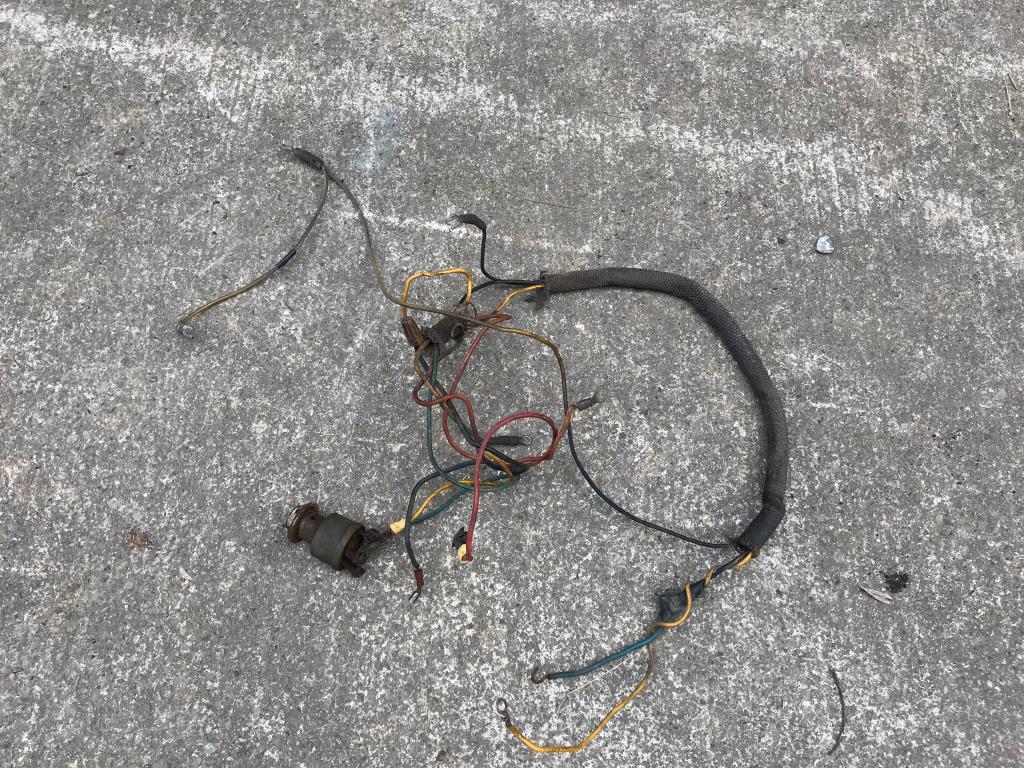
There was no way I was going to put this mess of cable back on so a new wiring loom was made later on.
Someone had tried to fix the coil bracket at some point so I fixed that.
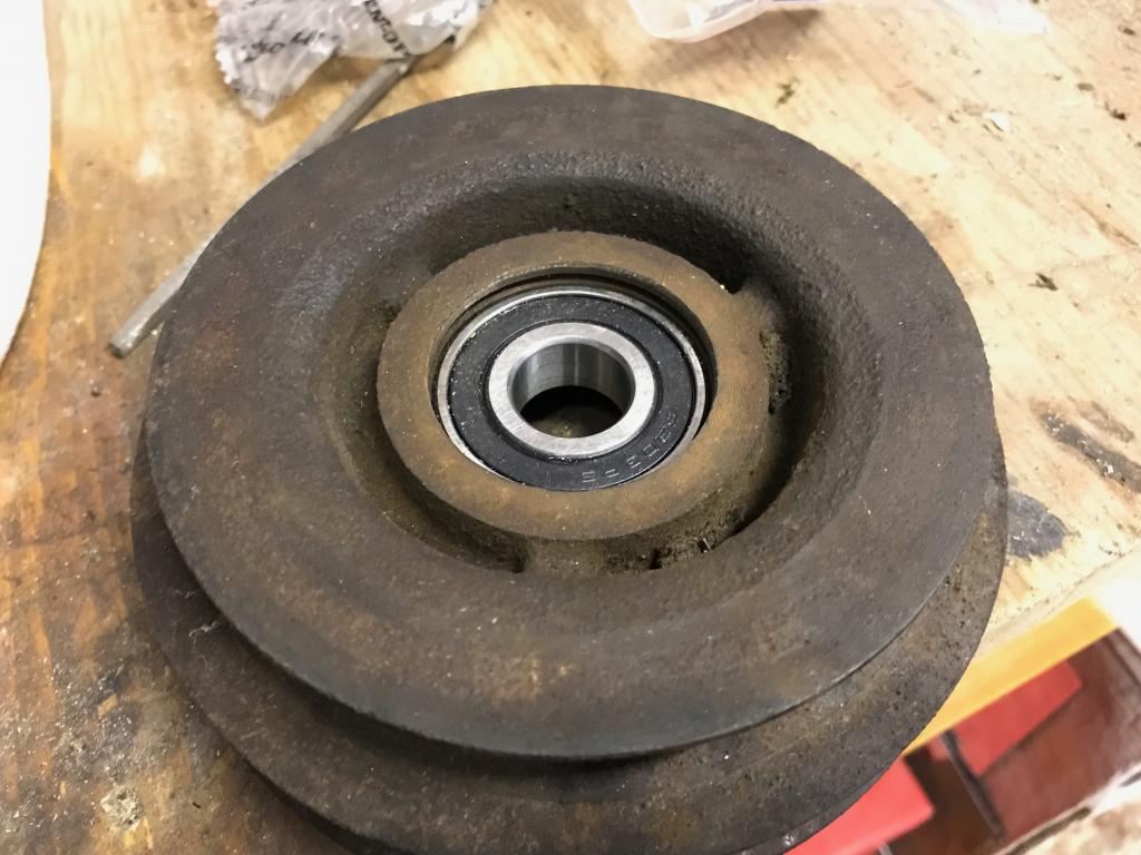
New idler bearing.
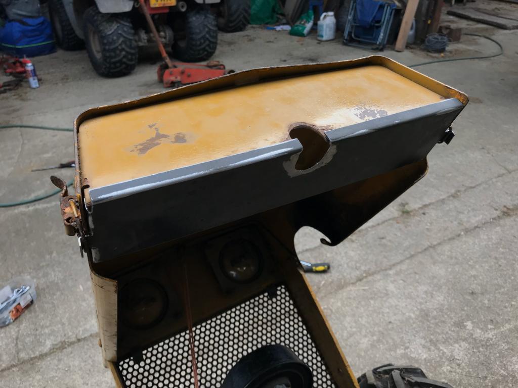
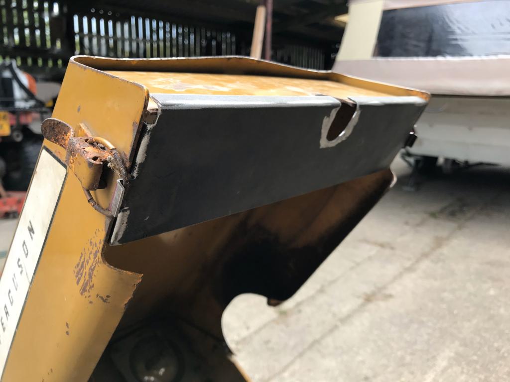
I gave the tin work a light sand then used some wax and buffed it up, looks great and will prevent rust.
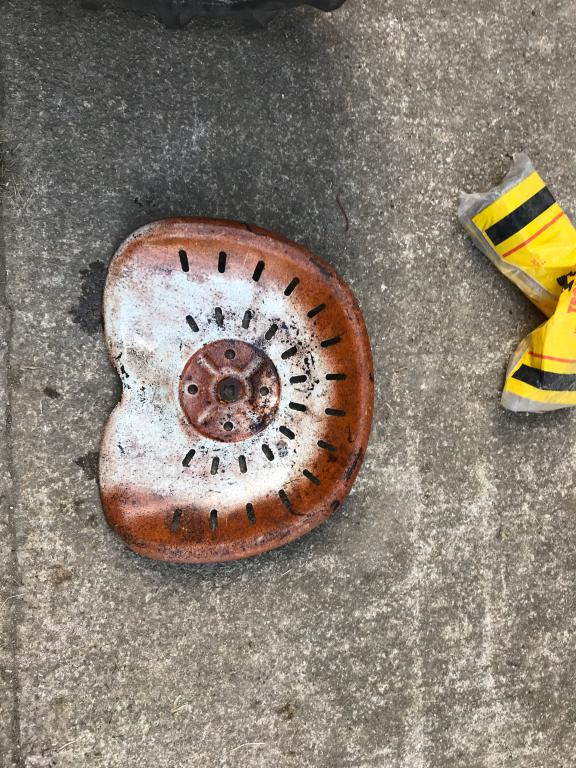
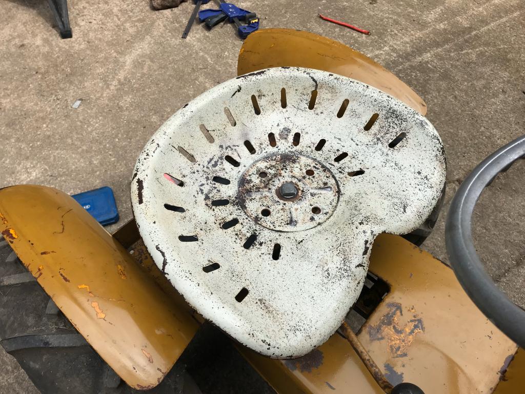
Focus turned to the seat which was rusty, with some wire wool and water I managed to clean it up nicely.
Great job on the wheels Chris! My RJ rear wheels were like that, only they had holes all the way round Hours spent with the mig and a grinder had them sorted out
After a busy year i'm finally getting round to posting some photos, nearly a year later!
so heres some photos.
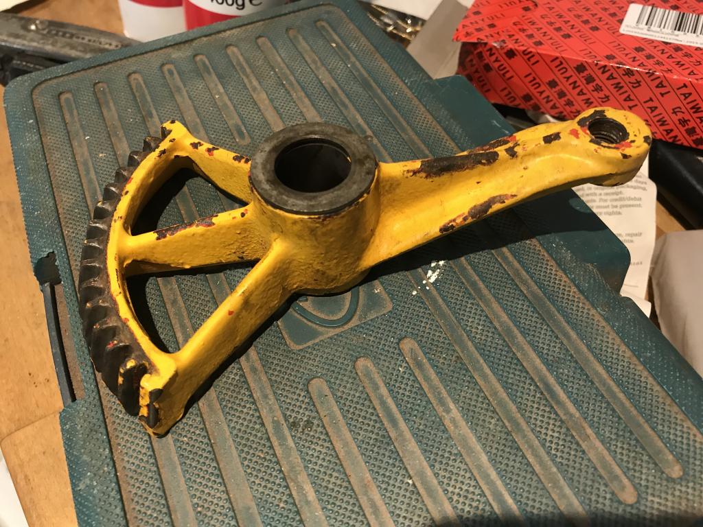
Steering gear after a cleanup, I like the fact you can see red paint under the yellow. This is because a MF7E is a rebranded and repainted moto mower which were red.
Steering column, needed a good cleanup but been well greased so no wear.
Looking better after a bit of a clean.
Will try post some more photos later, having difficulty uploading them
I sent it on 2019-12-09 09:57:25
Maybe it was spamming?
Tomas
Hi Tomas, yes you are correct, it had put your email in my spam, must have been because it’s international. I noticed it was last Monday you mailed so sorry about the delay, I’ve now replied, let me know if all is ok.
Good buy Joseph! I have the same one and you're not wrong about the flat pack, it took me quite a while to assemble it. I bought it from Belgium a few years ago and it still works great
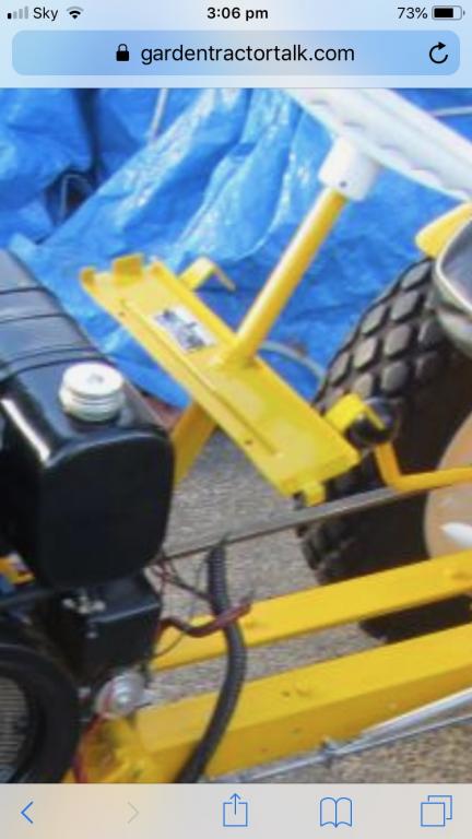
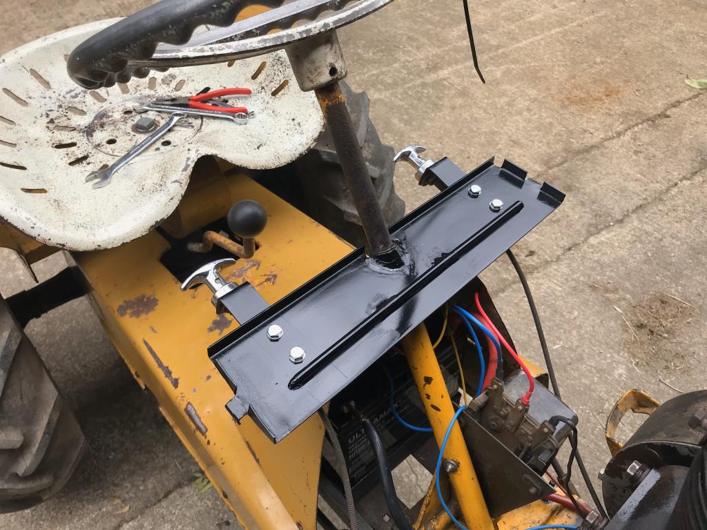
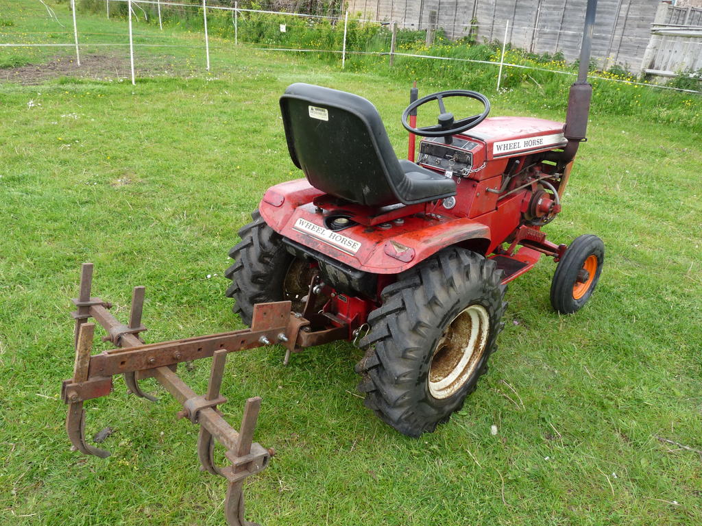
What You have is one third of the Wheelhorse implement package, Plough, Discs and Cultivator assemblies which all use the same mounting beam. I have the other two thirds, I'm missing the plough. Have a look in the Wheelhorse magazine 1981 on Red Square, it shows the setup.
The clevis part on the front can be fitted in either of two positions, one way up it's square to the beam for the discs or cultivator, or turned over it is at the correct angle for ploughing use.
The furrow wheel looks to be an addition, it's not shown in the original pictures.
I have the mouldboard and adjuster but no bracket or coulter for one of these, perhaps your missing plough
Wow, looks like its had a rough life! I look forward to seeing your process, we make the decals, if you require them, let us know. http://restorationdecals.co.uk/Westwood.htm Good luck!
No, a US seller was selling the crankshaft bearings on ebay and he had listed the bearing number, with that and Richards help I ordered some off ebay. It was just easier for me, i've heard many good things about Meetens though.


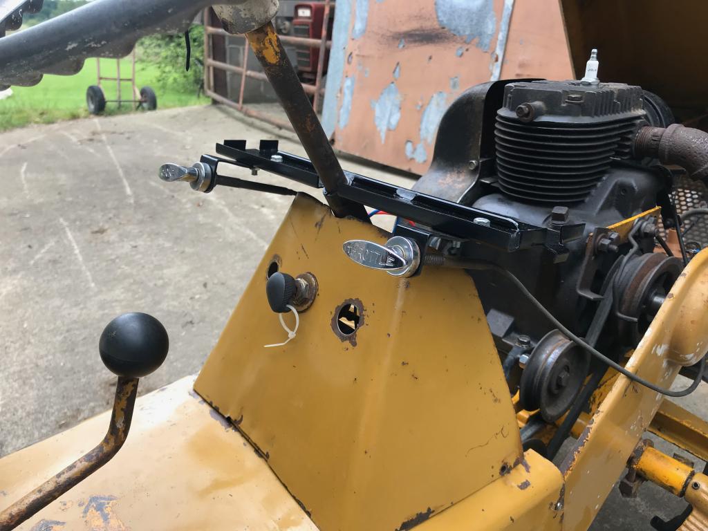
 I love the chrome control levers.
 .
.


") .
.
 Hours spent with the mig and a grinder had them sorted out


Wheel Horse Clevis Hitch
in Metal Shop
Posted
Cheers Norm, Once finished I’ll work out cost and let you know