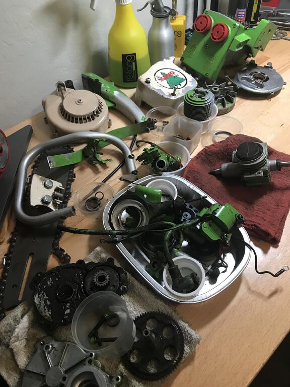
After hours of tedious clean up with dental tools the engine is finally free of green paint and I completely went through everything. I’m working on prepping all the body work now. I wasn’t expecting this to turn into a complete re-do but o’well, it should look nice all said and done.
Thanks for all the opinions, I’ve decided to go with the lime green.
PMackellow, thank you for the RAL number that’ll come in handy. I have a can of Kawasaki KX dirt bike frame paint from the mid-1990s on the way. If it’s not a close enough match I’ll look at the Lawnboy color - I didn’t even think to look at that when I started hunting.
You know what they say about opinions but I kinda like the lime green and it will break up the red and yellow on your shelf.
I always appreciate your opinions! I tend to agree with you, I’m kind of leaning towards keeping it lime green. As you point out, it will certainly help break up the color mix on the shelf. I think I found a very good color match, at least I hope so. I have it on order so we will see how close it is.
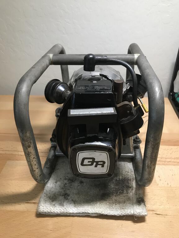
They do turn up occasionally in the UK, if I'm correct there are two that have made it to the US so far, I'll probably have a spare one available if anyone over there is interested. At least we now know how they were packed for shipping.
I’m interested!
Can’t wait to see the next batch of O&Rs you pick up....
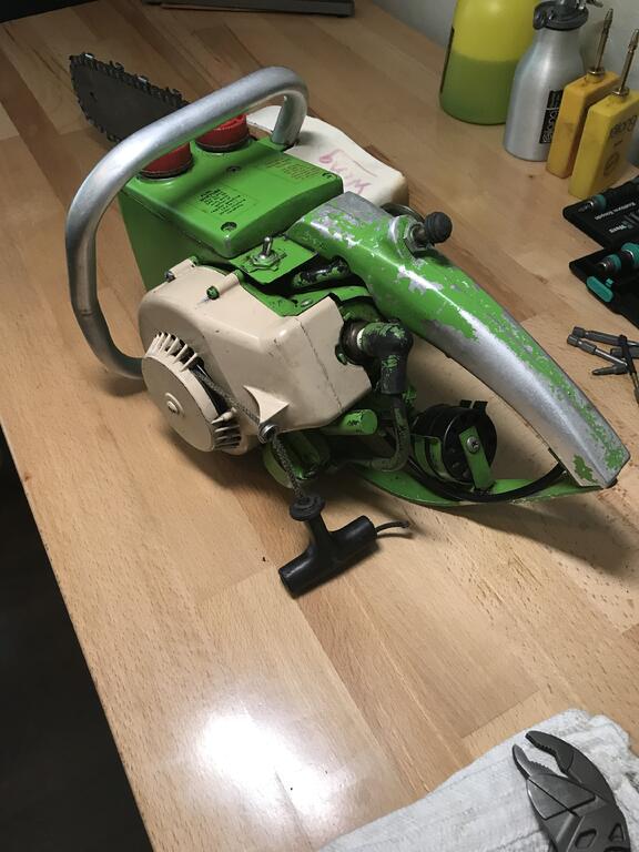
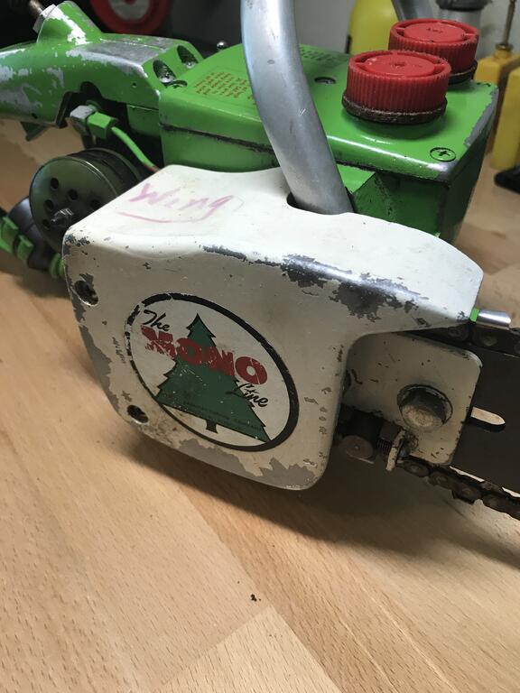
I’m in a bit of a quandary on this Mono saw. It looks like I’ll end up needing to do a full repaint. The lime green sticks well to the parts you don’t want it to and is flaking off the parts you’d like it to adhere well to. I’m just about done stripping all the engine parts since I don’t want those painted. While I’m not at all a big fan of the lime green color scheme, a part of me wants to paint it as close to the original as possible (minus the engine of course). However, with the paint failing and needing to repaint the whole thing anyway now would be the time to potentially go a different route with the color. Many other Mono saws are red or dark pine tree green. If I were to change colors I was thinking maybe an O&R red body and handle with white recoil and chain cover. This would also look nice with the new decals.
What would you all do? I think I can find a suitable lime green to repaint it but I’m not in love with lime green.
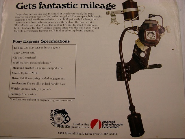
I’m just now seeing this thread and a David’s comment about the Pony Express address as Eden Prairie, MN. That’s where I use to live and I actually worked off of Mitchell Road, small world...
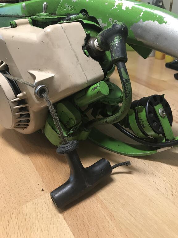
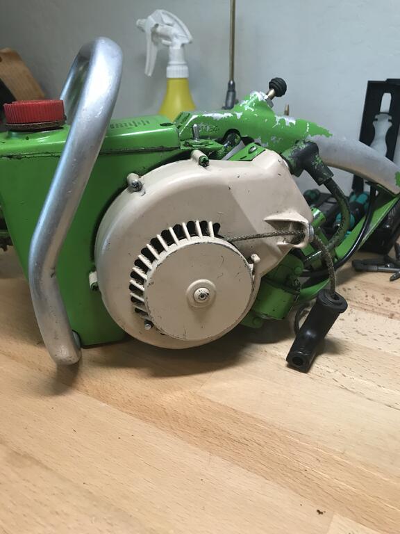
Got the recoil done and all back together. Unfortunately I wasn’t able to get it to run. It’s got spark and it sort of sputtered a couple times with the choke but never really got any signs of life at mid choke or run. Sort of seems like it’s not getting fuel for some reason. I mounted a temporary syringe of fuel above the carb and that didn’t work either, even after priming the carb several times. Strange, always a bummer after doing a complete rebuild... walking away for now and will try again another day...
Ok, so I just couldn’t leave it alone. It always drives me crazy not being able to get‘em going so I decided to give it another go. I cleared the carb again and adjusted the needle. Fired right up, sounds great! I’ll have to test the generator function the next time I run it. Now I can sleep tonight...
Thanks for all the research David, this is very helpful! I’ll have to take another look at the M6 threads. Mine shouldn’t be any different than yours. At least now with the correct pitch sizes I can start hunting for the correct screws.
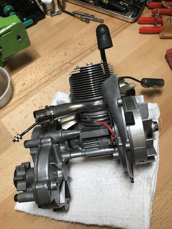
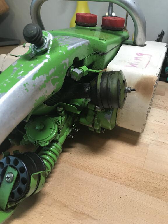
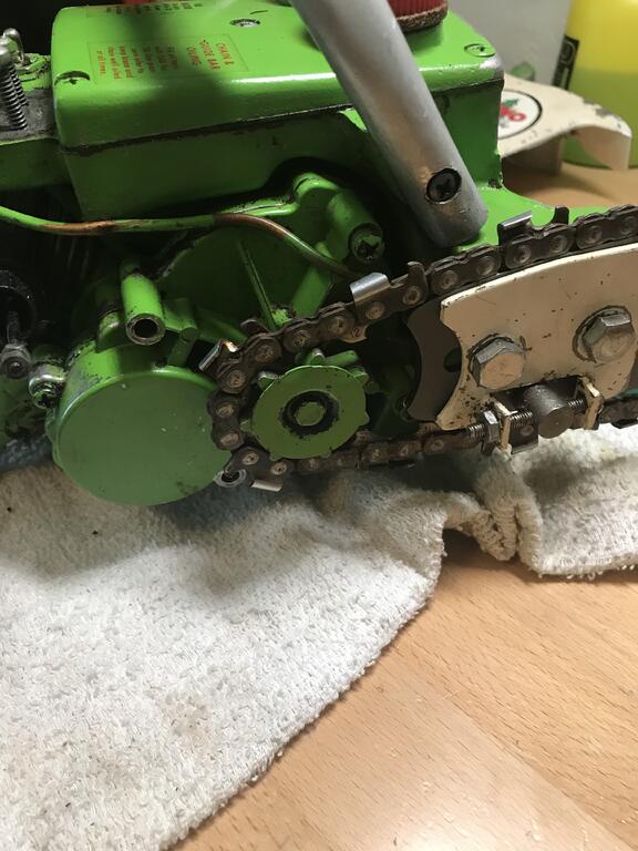
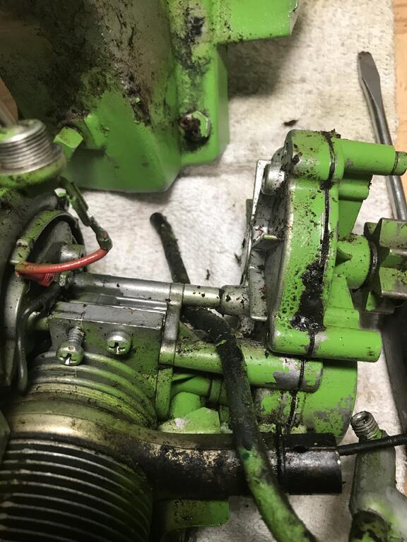
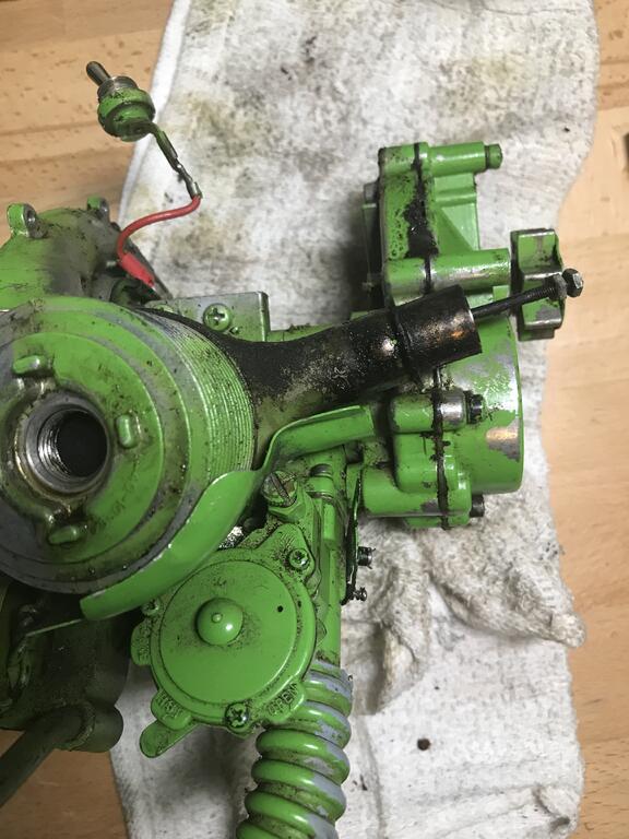
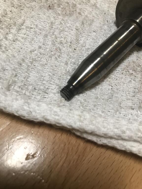
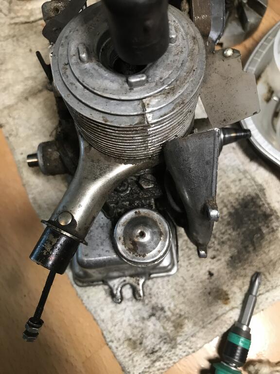
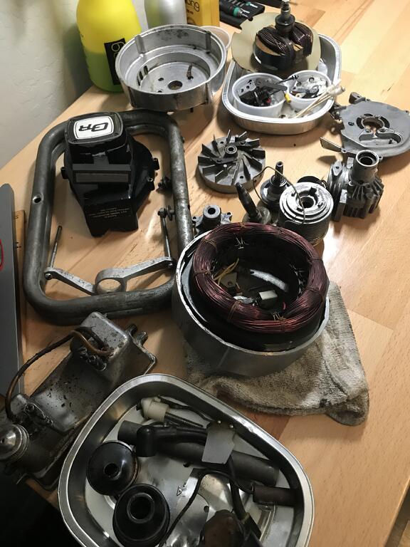
Not sure exactly what possessed me to jump into another chainsaw as my next project but I figured it was time to finally go through the Mono-Line. I got it all disassembled today. The gearbox is set up differently than most of the Orline saws. The chain sprocket is to the outside. Unfortunately a previous owner cut the crankshaft flywheel nut and ground it and the end of the shaft flat. A few of the threads are broken off too. It’s bad enough, and seems overly brittle, I’ll need to replace it if I can hunt down a used one. The screw that holds the chain sprocket was also cut in half, makes no sense to me... I can’t figure out why either of these modifications were thought to be necessary, frustrating when people do stuff like that.
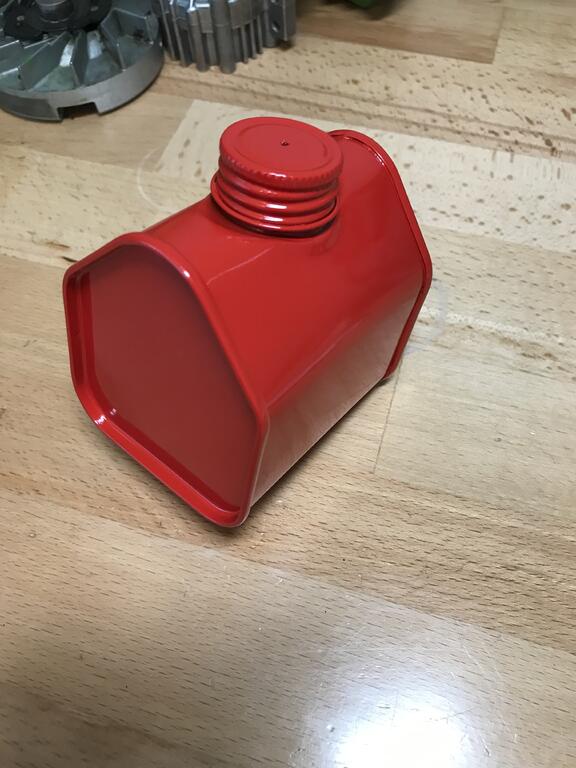
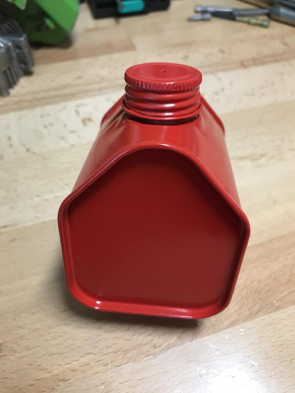
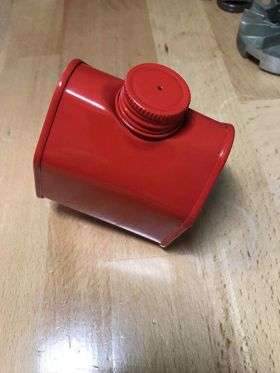
Found this cool shaped 8 oz can. It’s a good size and might make a neat tank for a test stand or maybe even with an O&R engine. Got it all sanded. soldered in the fuel fitting And drilled a small vent hole in the cap. Next up is to paint it O&R red.
Excellent, thank you. I need to get myself a thread gauge one of these days... they have to be metric (JIS), just not sure why the standard ones at the hardware store don’t work
If your engine has clear check valve diaphragm then it's probably OK, if it's the black rubber material (as used for the main diaphragm) then they do go bad, I've even had one where the part of it was completely missing.
I came across one of these for the first time just recently, ended up replacing it with a plastic check valve.
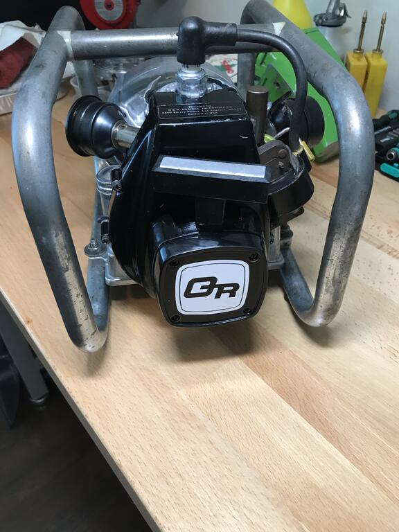
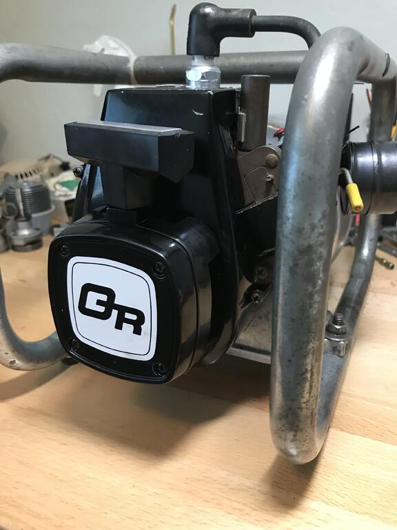
Yep, I was fortunate enough to land this one as well. I actually want to use this one some and I have a project in mind. The first one is way too nice to use since it’s almost new condition, I plan to keep it in good condition.
Yes I have seen similar engines on outboards, can you indicate which screws are missing and I could have a look at mine & see if I can work out the sizes.
David
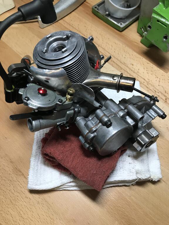
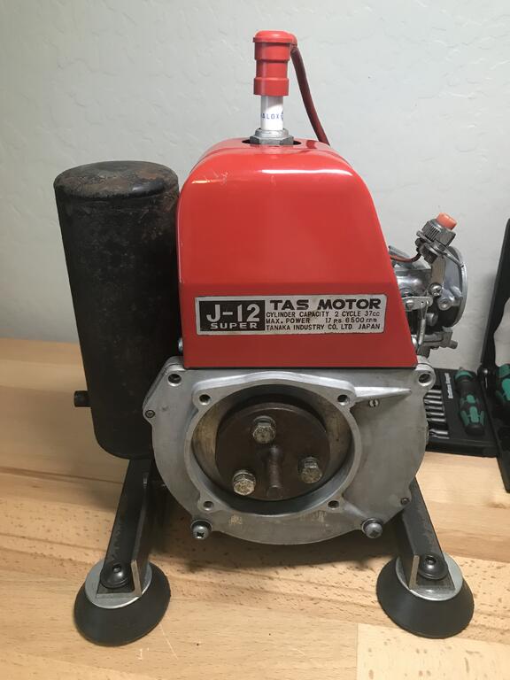
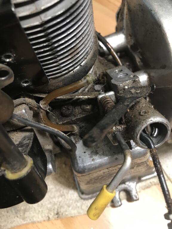
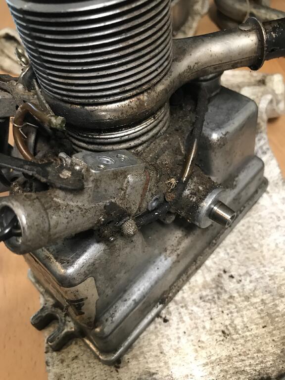
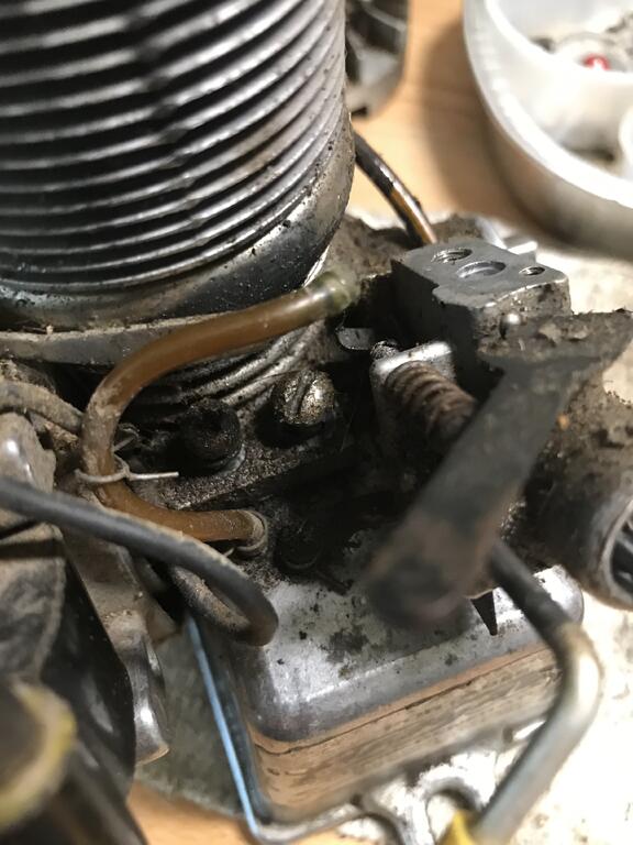
I’m missing one of the small screws on top that holds the cooling baffle/cover to the head and then I’m missing two of the main screws that hold the crankcase cover together (see just below each corner of the red cover with the J-12 decal).
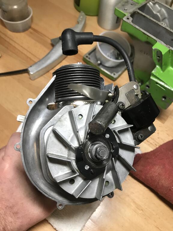
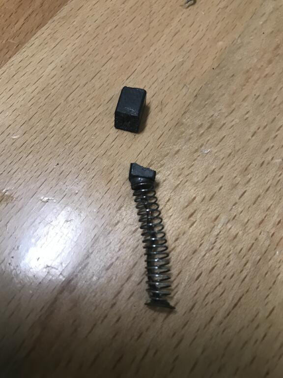
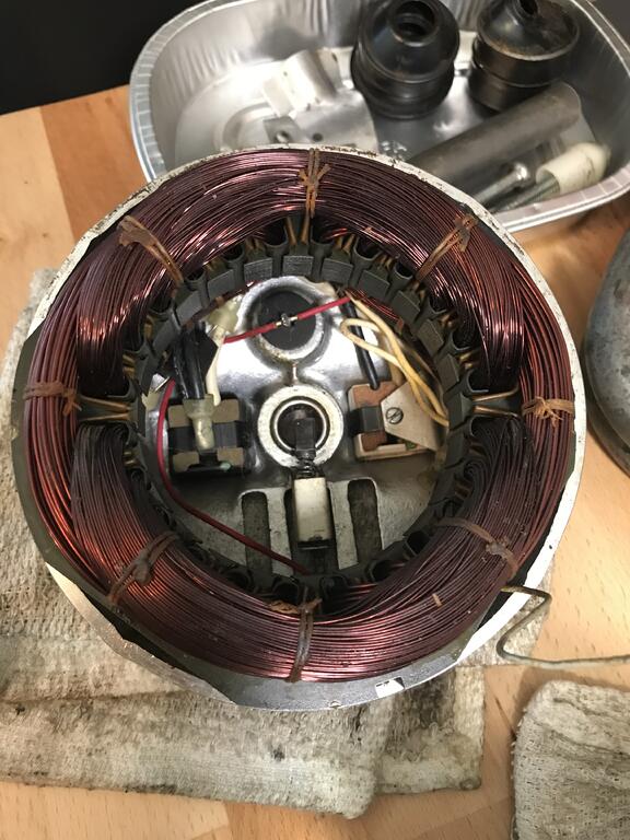
Indeed, you need another four hands for this operation. It takes two hands just to align the windings with the bearing while fishing the wire through and everything As it all slides together. Then, just as it engages the bearing you’re suppose to somehow use a dental pick through the front of the bearing hole, while also holding a flashlight, to push down the brush and slide it all together. One little slip and snap... just like what happened to me!
Bad news, while trying to get everything lined up to put the generator parts back together the little brush bot pinched and snapped Hopefully I can find a suitable replacement.
Ha, tell me about it... This was a busy week with work and kids getting back to school- not much time for O&Rs. Are you seeing any daylight yet on your end to get back to some O&R projects?
Making some good progress on rebuilding a Life-Savr. The paint on the recoil spring cover is in really poor condition and flakes off in chunks when you touch it so I’m repainting that piece. It was so saturated in oil and grease that the paint failed. I think the rest of the paint on the recoil cover will hold up a little longer and I want to keep it as original as possible. I’ll be putting on a new decal since the one on their basically chipped off and was pretty faded.
Thanks to JustO&R I was able to buy a new front shaft seal (Timken/Nationals 342805), looks to be a perfect fit. Fortunately I had a couple NOS induction case gaskets, the ones that are slightly thicker material - kind of like the cylinder head exhaust collector gaskets.
The recoil rope reel was also damaged but I was able to find a used spare one in my parts stash. Should be able to start reassembly and finish the painting today.


 Those drills are really neat!

 missing one of the small screws on top that holds the cooling baffle/cover to the head and then I’m missing two of the main screws that hold the crankcase cover together (see just below each corner of the red cover with the J-12 decal).

 Hopefully I can find a suitable replacement.
Ohlsson & Rice: Mono-Line Chainsaw
in Ohlsson and Rice
Posted
Thanks! I always underestimate how tedious it is, you’d think I would have learned my lesson by now.
Here’s the inside of the gas and oil tank for any future reference.