

Anglo Traction
-
Content Count
1,124 -
Joined
-
Last visited
-
Days Won
144
Reputation Activity
-

 Anglo Traction got a reaction from Cub Cadet in A Mystery Roaring Twenties Refurb.......hopefully!
Having done some swatting up on machining this version of Phosphor Bronze (PB104) and looking for more endorsements that it is the correct stuff for the job, I went ahead.
The Gudgeon Pin obtained from the donor engine was a god send, as I had visions of having to make one and pay for the cylindrical grinding and polishing to size.
I went all over it with a micrometer, noting and marking sizes. I found a slight taper of 0.0002"(0.0051mm) end to end.
The most wear I found was 0.0006" (0.0152mm), so I aimed for closest fit possible to that. Strangely, the pin diameter is neither metric, or imperial and so worked to 0.4915" -
Started with 3/4" (19.05mm) dia stock rod. I knew the stuff was a bit 'sticky' when machining. Using 1 part cutting oil and 10 parts White spirit (mineral spirits I believe in U.S)
I followed a set process of repeated shallow depth drilling, followed up by boring and progressively enlarging the bore to keep the friction heat down. Stayed only warm to the touch throughout, so was happy with that.
Got to 31/64" (0.4843") leaving me about 0.0072" to finish. Moved the part still in the chuck over to the Mill and fitted to the rotary table for marking out and drilling the oil way-
You may see on the old bushing, a circle just below the oil way. Well I scribed the circle while it was still in the con rod due no hole visible.
It was not until I removed the bushing that I found the oil way there. So either it was originally fitted like that, or it moved round ?.
Anyway. after drilling the hole, it was back to the lathe with it to finish the bore to size and turn the outer diameter to a press fit-
Put shallow helical groove in the bore for oil distribution, then parted off and finished ready for fitting-
A bit of relief to get that part out of the way, so continued to chip away at various bits. Tank Cap was plugged, fuel tap was seized up and clogged.
Also has a filter in the lower section. All cleaned ready.
The back of the Armature Plate lightly cleaned to keep the age look and proceeded to make the rusted, rotted parts. Spring wire HT cap retainer and the armature plate lever. Both Oil blackened and heat treated. New HT Lead and ready now to fit the piston-
You may also notice the Lock Screw for the armature plate looks a bit better now.
The black markings on the piston are not wear or damage. I believe they are fine grinding marks from when it was either being prepped as a casting ready for machining, or after machining to allow for some skirt clearance and oil retention.
Carefully checked and marked the parts for correct orientation and order of assembly, starting with the small end bushing and avoiding any strain on the con rod and bearings-
That bushing should not move in a hurry now!.
And with another 'pre fit' check, the ceremonial oiling and fitting of the piston -
....................tbc
-
Anglo Traction got a reaction from Cub Cadet in A Mystery Roaring Twenties Refurb.......hopefully!
No Norm, I would not dare to do a blind 2 stroke cylinder with large transfer ports. Don't have the gear.
It should be done properly on a machine that limits the oscillating travel of the rotating (multi) stones at the right point and that the stones can't catch on the ports.
It should only really be done when the bore can be measured accurately to fit new rings so end clearance is minimal.
This bore surprisingly only had staining with no rust pitting or scoring, despite the engine being locked solid until my releasing fluid did the job and freed it up.
Thought I had a pic of the cleaned up bore, but can only find this one from after removing the cylinder-
I was really quite impressed with the smoothness of the cleaned up bore and struggled to find any wear lips or tram lines. I think the low skirt piston ring served to maintain even bore wear and prevented piston slap wear. The single replacement ring will have to bed in as is, but will be assisted with increase of Petroil ratio and 40 weight oil instead of 30 wt.
I was not happy with my attempts to clean the crank case out as much as possible without splitting the cases.
After several attempts to remove the drive sprocket from the Crank, I gave up.
It is worn, but serviceable for now and I could not position it in my 12 ton press to apply correct force properly without risk of strain or damage to it.
So I split the cases which showed the cleaning limit lines-
Just as well I split them, as the oil galleries to the Crank bushings were solidly blocked with carbon, as well as the surfaces .
Armed with a few old toothbrushes etc, it all cleaned up nicely and very smooth shiny surfaces at the contact points.
Next pic shows that this engine was designed to run with the cylinder vertically.
The recessed valleys each side above the shaft bushings collect and channel oil to the galleries for lubrication.
They can't do that so well when it's in a horizontal plane. The other point is that the crank case drain plug is rendered useless!.
Another observation is the design of a separate lubrication facility where oil is passed into the crankcase via a hollow mounting stud or bolt, you can see the recess around the bolt hole in lower left and right positions of the case halves in the pic below-
The separate oil system is not used on this application, so uses premixed petrol and oil (petroil).
I checked the crankshaft end float before splitting the cases (0.0055" or 0.15mm), it's well within limits, so I measured the old washer (gasket) thickness and cut out a new one.
Quality brown paper was used with a thickness of 0.0045". Thought I'd stick to tradition and use shellac to dress the washer/gasket and bolted up the cases.
Left to set overnight, tweaked the bolts and checked the end float and got 0.006" . Real happy with that, so gave it some oil in the important bits.
Now that it was all clean, I could check the wear limits of the crank bushings. up, down, left and right movement on both sides using about 20 ft lbs (27.12 Nm) pressure.
Flywheel side was good with only around 0.005" in all points. Drive side was a bit excessive on the chain strain line (0.010") , but good up down and right.
Just as well as only option would be to make new one(s)......no thanks!.
Established the type of bronze I needed and ordered some PB104................................... TB Cont'd .
-
Anglo Traction got a reaction from Cub Cadet in A Mystery Roaring Twenties Refurb.......hopefully!
Well, I hope it provides some reading entertainment for you Gents. Afraid a simple 'Oily Rag' refurb has escaped me again Norm.
The cylinder had to have the various bits removed from it. Luckily, the completely blocked Decompression Valve relented ok and the bypass tube plug in the head undid,
but the eroded exhaust flange nuts had to be cut and split-
While still dealing with the Cylinder bits, I had to start searching for somewhere to have new Rings made. A few hours interweb searching later, I'd found reference
to a restoration of a 1922 CWS Federal Motor bicycle. It had the same engine as this one and reference was made to an engineering firm that did all the work including making new Rings!.
So I fired off an enquiry and received a good reply with price estimates for each item of work, i.e, a cylinder hone and 3 piston rings to fit.
Long story short, I built a strong protective box to transport the parts and to return them in it-
Disappointed to say the least after receiving an email saying 'all done' and sorry for the cost/charge as was more difficult than he expected!.
When it arrived, all they had done was to make one piston ring!.
They left the 2 old rings on which I sent for their pattern reference, did not hone the bore and charged double for one ring.
So with fingers burnt again (as some here will know) from remote commission work, despite endorsements, my faith in British engineering firms has diminished completely and will now only deal with 'face to face' arrangements.
No option but to proceed and have faith that the wear, although greater than stated limits, will be ok for it to run ok. The point being that it has been fully de carbonised and so loses some assistance the carbon can offer in compression retention.
Onward's we go, and started the servicing of the De-Comp valve. Solid with carbon and parts rusted away. Cleaned up and made new clamping screw for the lever pivot collar and pivot pin-
Valve seat and face cleaned up ok and only needed lapping with scrapings from p600 emery and 'T' cut. New valve nut, 1/16" cotter/split pin and will have new copper washer.
Lever pivot hole egg shaped, so bored it out larger and fitted a bronze bush (not in pic).
Next job was to obtain the correct type of bronze rod for the small end bushing................................... T B Cont'd
-
Anglo Traction got a reaction from Cub Cadet in A Mystery Roaring Twenties Refurb.......hopefully!
Well, perhaps just a subdued British 1920s refurb !
I'm hoping I'm not tempting fate here by starting this before I am confident it can be saved and bring back to working order, but I have reached a point where I am reasonably confident.
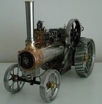
The intention is not just to keep this a mystery 'til near the end, but to document the challenges of working on what can only be described as an old garden sculpture that used to be a machine.
I reckon that this machine had a useful life of about 7- 10 years from early 1922. Thereafter, it was abandoned and left outside for at least 20 years with only the oil laden dirt to protect it.
It had later (in the mid 50s) been moved to inside an old van and stored there until it saw the light of day back in Sept 18. Always been in the original purchaser's family possession until then.
Being of the ilk that likes a challenge, this may be harder than I've been used to in the past. The engine is obsolete and I have no parts information for it, or the machine's frame.
I have acquired some excellent info on the engine and carburettor and has allowed me to progress with checking wear tolerances and set up.
I make no apologies for all the detail in the thread, as I hope it may be of use to anyone who also attempts to tackle an old Villiers engine etc.
Work began on the engine to see if it was salvageable. This is the Villiers MkV 269cc 2 stroke of 1922.
It is the engine version that was first to use the flywheel magneto patented around 1920 by Villiers. Very simple and effective at that time-
Known as the large flywheel type Magneto (8 1/2" dia or 216mm), the engine had undergone several revisions since it's inception in 1913.
Designed originally for motor bicycles, this one has a variable timing Armature back plate, but has no use for this machine's application, as the ignition timing is for TDC!.
Flywheel is matched to this Armature Plate having identical numbers stamped on them.
Condition of the engine externally was badly corroded Fins etc on most upper parts, as you will see in various pics.
Internally was pretty dirty and no evidence of ever having been de-carbonised as it had a very thick layer inside the piston. Obviously the rings were seized after about 80 years-
This engine, being very early 1922 was still fitted with 3 Rings. Later 1922 engines appear to have only 2 at the top?. Production of this engine ceased in September of '22' .
I had suspected the wear in this engine to be quite bad, as it was designed to be upright and not horiziontally mounted, but was surprised that it was reasonably good as cleaning progressed.
Years of oily dirt helped to keep the corrosion down in certain areas which can be seen in this pic-
Note:- the chain was fitted to provide restraint while undoing the Crankshaft nut to remove the Fan.
Once the engine was liberated from the frame, the internals were dismantled. Piston gudgeon (wrist pin) pin is the 'Drive In/Out' type and locked with Cotter/Spit pins.
With this removed I found serious wear to the pin and con rod 'Small End' bushing. The cause being no oil hole visible to allow lubrication!.
Having been blessed with access to a donor engine of the later type (2 piston rings), I obtained a good and little worn gudgeon pin, but had no option other than to make a new 'small end' bushing.
I put that to one side while further evaluation was made. Cylinder and it's bore was cleaned and looked quite good considering and maybe just a hone required.
Despite virtually no scoring in the bore or the ring faces, the wear limit of the ring gap is excessive and really needs new ones and a hone. Piston is good.
Donor engine bore etc are poor condition.
Valuable information came by the way of old editions of 2 different books by motor cycle enthusiasts of the 30s onwards, namely Cyril Grange & B.E Browning.
Between the two books, I was able to extract all the max wear tolerances and most procedures.
I did have a problem finding the best way to remove the large brass retaining disc/washer that retained the Armature Plate. It also appeared distorted or cup shaped -
I was also concerned about the wear marks from the Flywheel on the armature plate's face, just visible top L/R of pic above.
Disc/washer was a press fit onto the Crankshaft, so I went carefully and used 2 small levers to evenly prize it away with the expectation of finding an oil seal of some type behind it, only to find nothing!.
Never had any oil seal fitted and no sign of leaks etc!!, all metal running fits. I reckon the cup shaped look of the washer was from strain of some kind and should be flat?.
At the same time, I had fears of the Lock Screw at the back of the Plate being totally seized, as it only has a screwdriver slot, or what was left of it-
I found the heftiest flat bladed lever I could use and to my surprise after a little of my releasing fluid, it unscrewed smoothly and the plate could be removed exposing the corrosion and rot-
The list of jobs was gradually increasing the more I delved, and the damage from it's last runs was appearing.
I tested the HT Coil using ohms resistance just to endorse it was dead, found there was still continuity in the 2nd winding, but only had half of the normal resistance. Going new anyway.
modern version of this pre WW2 HT Coil is available, as well as the HT Lead, but not cheap.
So by this point, I knew what was needed, what could be done and obtained to get this running again. ......soon to be cont'd.
-
 Anglo Traction got a reaction from Alan in A Mystery Roaring Twenties Refurb.......hopefully!
Having done some swatting up on machining this version of Phosphor Bronze (PB104) and looking for more endorsements that it is the correct stuff for the job, I went ahead.
The Gudgeon Pin obtained from the donor engine was a god send, as I had visions of having to make one and pay for the cylindrical grinding and polishing to size.
I went all over it with a micrometer, noting and marking sizes. I found a slight taper of 0.0002"(0.0051mm) end to end.
The most wear I found was 0.0006" (0.0152mm), so I aimed for closest fit possible to that. Strangely, the pin diameter is neither metric, or imperial and so worked to 0.4915" -
Started with 3/4" (19.05mm) dia stock rod. I knew the stuff was a bit 'sticky' when machining. Using 1 part cutting oil and 10 parts White spirit (mineral spirits I believe in U.S)
I followed a set process of repeated shallow depth drilling, followed up by boring and progressively enlarging the bore to keep the friction heat down. Stayed only warm to the touch throughout, so was happy with that.
Got to 31/64" (0.4843") leaving me about 0.0072" to finish. Moved the part still in the chuck over to the Mill and fitted to the rotary table for marking out and drilling the oil way-
You may see on the old bushing, a circle just below the oil way. Well I scribed the circle while it was still in the con rod due no hole visible.
It was not until I removed the bushing that I found the oil way there. So either it was originally fitted like that, or it moved round ?.
Anyway. after drilling the hole, it was back to the lathe with it to finish the bore to size and turn the outer diameter to a press fit-
Put shallow helical groove in the bore for oil distribution, then parted off and finished ready for fitting-
A bit of relief to get that part out of the way, so continued to chip away at various bits. Tank Cap was plugged, fuel tap was seized up and clogged.
Also has a filter in the lower section. All cleaned ready.
The back of the Armature Plate lightly cleaned to keep the age look and proceeded to make the rusted, rotted parts. Spring wire HT cap retainer and the armature plate lever. Both Oil blackened and heat treated. New HT Lead and ready now to fit the piston-
You may also notice the Lock Screw for the armature plate looks a bit better now.
The black markings on the piston are not wear or damage. I believe they are fine grinding marks from when it was either being prepped as a casting ready for machining, or after machining to allow for some skirt clearance and oil retention.
Carefully checked and marked the parts for correct orientation and order of assembly, starting with the small end bushing and avoiding any strain on the con rod and bearings-
That bushing should not move in a hurry now!.
And with another 'pre fit' check, the ceremonial oiling and fitting of the piston -
....................tbc
-
 Anglo Traction reacted to Ian in Honda MadTrax V Twin Quad.. Nearly Finished.. Woo Hoo
Hi Norm, I know which plastic toy snakes your talking about, the ones with lots and lots of bendy joints.. Used to have one a a kid.. And yes I see why the exhaust reminds you of one..
You were lucky with the adder, that could of hurt a bit!
Hi John, good to see you back... I'm also struggling to find forum time at the mo.. Why does life has to be so busy???
The finished product isn't too far away now as you will see.
Glad you liked the camera motion thingy, it's gets some more use in the next video
For a few days there wasn't anything I could do on MadTrax until the paint I had ordered turned up, so.....
I had a bit of a tidy and clean up in the lathe corner of the workshop.
The white doored paint cupboard came out from the corner behind the lathe and now lives in a place I can actually reach it.
The "lathe shelf" now looks a lot neater and emptier..
As most of the smaller tools now live in this labeled cabinet..
And to finish off the lathe got a much overdue clean up..
Finally last weekend my long awaited paint turned up, so Monday was paint the frame and engine day
Which made Tuesday "get the engine, transfer box and rear end in" day.. A bit thank you to Rob for all your help with this.. Ta muchly mate..
More parts bolted back on the frame, most of the front end..
A "few" freshly painted parts hanging about the place drying..
And that is where the rebuild has got to as of yesterday..
To finish off this update have a couple of videos..
Enjoy
-
Anglo Traction reacted to Alan in HALF a HORSE.
Think I am near the end of this project now, apart from sorting teething problems out. During runs at last years shows, the clutch to gearbox drive chain kept locking up. The original chain tensioner wasn't up to the job. This has now been changed but not yet tested. Fingers crossed. There is still too much free play in some of the steering joints. Still working on how to overcome this.
Mark ( meadowfield ) made up the decals. Thanks Mark. Couldn't get good photo's in my garage. Too many reflections etc with or without flash which also shows up dust specs. Need to retake in daylight, as and when. Dummy light and ignition switches were fitted but think the key could be slightly larger.
A few more taken at the shows.
And the almost finished trailer.
Finally, the tractor needed someone to drive it while I just sat and enjoyed the scenery while being dragged behind. Hours of searching for a suitable size person resulted in nothing. As I wasn't allowed to borrow my 15 month old great grandson, ( he would have been cable tied on to stop him falling off ), the next best thing was to make something up.
A head was obtained from China. Cheap as usual but a bit pink looking. His face was weathered, well he is a farm boy, using some of my old modelling paints which were well past the sell by date Some people say he is a little too brown, but he doe's get out in the sun a lot.
An ice cream tub, wood, foam and tape were used to bring him to life. My great grandson donated some of his clothes. Calvin, that's his name, was knocked up in a hurry just before the shows, and had to make do with rough and ready gloves and hat until something better comes along.
Here he is having fun and being followed by a Doc Brown ( from Back to the Future ) look a like. Don't all laugh at once.
As said above, I think this just about wraps this project up, apart from a few modifications and better photo's of the decals. What next ? Watch this space.
PS. Calvin had to wear sunglasses when looking at his passenger.
-
 Anglo Traction got a reaction from S1g in A Mystery Roaring Twenties Refurb.......hopefully!
No Norm, I would not dare to do a blind 2 stroke cylinder with large transfer ports. Don't have the gear.
It should be done properly on a machine that limits the oscillating travel of the rotating (multi) stones at the right point and that the stones can't catch on the ports.
It should only really be done when the bore can be measured accurately to fit new rings so end clearance is minimal.
This bore surprisingly only had staining with no rust pitting or scoring, despite the engine being locked solid until my releasing fluid did the job and freed it up.
Thought I had a pic of the cleaned up bore, but can only find this one from after removing the cylinder-
I was really quite impressed with the smoothness of the cleaned up bore and struggled to find any wear lips or tram lines. I think the low skirt piston ring served to maintain even bore wear and prevented piston slap wear. The single replacement ring will have to bed in as is, but will be assisted with increase of Petroil ratio and 40 weight oil instead of 30 wt.
I was not happy with my attempts to clean the crank case out as much as possible without splitting the cases.
After several attempts to remove the drive sprocket from the Crank, I gave up.
It is worn, but serviceable for now and I could not position it in my 12 ton press to apply correct force properly without risk of strain or damage to it.
So I split the cases which showed the cleaning limit lines-
Just as well I split them, as the oil galleries to the Crank bushings were solidly blocked with carbon, as well as the surfaces .
Armed with a few old toothbrushes etc, it all cleaned up nicely and very smooth shiny surfaces at the contact points.
Next pic shows that this engine was designed to run with the cylinder vertically.
The recessed valleys each side above the shaft bushings collect and channel oil to the galleries for lubrication.
They can't do that so well when it's in a horizontal plane. The other point is that the crank case drain plug is rendered useless!.
Another observation is the design of a separate lubrication facility where oil is passed into the crankcase via a hollow mounting stud or bolt, you can see the recess around the bolt hole in lower left and right positions of the case halves in the pic below-
The separate oil system is not used on this application, so uses premixed petrol and oil (petroil).
I checked the crankshaft end float before splitting the cases (0.0055" or 0.15mm), it's well within limits, so I measured the old washer (gasket) thickness and cut out a new one.
Quality brown paper was used with a thickness of 0.0045". Thought I'd stick to tradition and use shellac to dress the washer/gasket and bolted up the cases.
Left to set overnight, tweaked the bolts and checked the end float and got 0.006" . Real happy with that, so gave it some oil in the important bits.
Now that it was all clean, I could check the wear limits of the crank bushings. up, down, left and right movement on both sides using about 20 ft lbs (27.12 Nm) pressure.
Flywheel side was good with only around 0.005" in all points. Drive side was a bit excessive on the chain strain line (0.010") , but good up down and right.
Just as well as only option would be to make new one(s)......no thanks!.
Established the type of bronze I needed and ordered some PB104................................... TB Cont'd .
-
Anglo Traction got a reaction from S1g in A Mystery Roaring Twenties Refurb.......hopefully!
Well, I hope it provides some reading entertainment for you Gents. Afraid a simple 'Oily Rag' refurb has escaped me again Norm.
The cylinder had to have the various bits removed from it. Luckily, the completely blocked Decompression Valve relented ok and the bypass tube plug in the head undid,
but the eroded exhaust flange nuts had to be cut and split-
While still dealing with the Cylinder bits, I had to start searching for somewhere to have new Rings made. A few hours interweb searching later, I'd found reference
to a restoration of a 1922 CWS Federal Motor bicycle. It had the same engine as this one and reference was made to an engineering firm that did all the work including making new Rings!.
So I fired off an enquiry and received a good reply with price estimates for each item of work, i.e, a cylinder hone and 3 piston rings to fit.
Long story short, I built a strong protective box to transport the parts and to return them in it-
Disappointed to say the least after receiving an email saying 'all done' and sorry for the cost/charge as was more difficult than he expected!.
When it arrived, all they had done was to make one piston ring!.
They left the 2 old rings on which I sent for their pattern reference, did not hone the bore and charged double for one ring.
So with fingers burnt again (as some here will know) from remote commission work, despite endorsements, my faith in British engineering firms has diminished completely and will now only deal with 'face to face' arrangements.
No option but to proceed and have faith that the wear, although greater than stated limits, will be ok for it to run ok. The point being that it has been fully de carbonised and so loses some assistance the carbon can offer in compression retention.
Onward's we go, and started the servicing of the De-Comp valve. Solid with carbon and parts rusted away. Cleaned up and made new clamping screw for the lever pivot collar and pivot pin-
Valve seat and face cleaned up ok and only needed lapping with scrapings from p600 emery and 'T' cut. New valve nut, 1/16" cotter/split pin and will have new copper washer.
Lever pivot hole egg shaped, so bored it out larger and fitted a bronze bush (not in pic).
Next job was to obtain the correct type of bronze rod for the small end bushing................................... T B Cont'd
-
Anglo Traction got a reaction from Alan in A Mystery Roaring Twenties Refurb.......hopefully!
No Norm, I would not dare to do a blind 2 stroke cylinder with large transfer ports. Don't have the gear.
It should be done properly on a machine that limits the oscillating travel of the rotating (multi) stones at the right point and that the stones can't catch on the ports.
It should only really be done when the bore can be measured accurately to fit new rings so end clearance is minimal.
This bore surprisingly only had staining with no rust pitting or scoring, despite the engine being locked solid until my releasing fluid did the job and freed it up.
Thought I had a pic of the cleaned up bore, but can only find this one from after removing the cylinder-
I was really quite impressed with the smoothness of the cleaned up bore and struggled to find any wear lips or tram lines. I think the low skirt piston ring served to maintain even bore wear and prevented piston slap wear. The single replacement ring will have to bed in as is, but will be assisted with increase of Petroil ratio and 40 weight oil instead of 30 wt.
I was not happy with my attempts to clean the crank case out as much as possible without splitting the cases.
After several attempts to remove the drive sprocket from the Crank, I gave up.
It is worn, but serviceable for now and I could not position it in my 12 ton press to apply correct force properly without risk of strain or damage to it.
So I split the cases which showed the cleaning limit lines-
Just as well I split them, as the oil galleries to the Crank bushings were solidly blocked with carbon, as well as the surfaces .
Armed with a few old toothbrushes etc, it all cleaned up nicely and very smooth shiny surfaces at the contact points.
Next pic shows that this engine was designed to run with the cylinder vertically.
The recessed valleys each side above the shaft bushings collect and channel oil to the galleries for lubrication.
They can't do that so well when it's in a horizontal plane. The other point is that the crank case drain plug is rendered useless!.
Another observation is the design of a separate lubrication facility where oil is passed into the crankcase via a hollow mounting stud or bolt, you can see the recess around the bolt hole in lower left and right positions of the case halves in the pic below-
The separate oil system is not used on this application, so uses premixed petrol and oil (petroil).
I checked the crankshaft end float before splitting the cases (0.0055" or 0.15mm), it's well within limits, so I measured the old washer (gasket) thickness and cut out a new one.
Quality brown paper was used with a thickness of 0.0045". Thought I'd stick to tradition and use shellac to dress the washer/gasket and bolted up the cases.
Left to set overnight, tweaked the bolts and checked the end float and got 0.006" . Real happy with that, so gave it some oil in the important bits.
Now that it was all clean, I could check the wear limits of the crank bushings. up, down, left and right movement on both sides using about 20 ft lbs (27.12 Nm) pressure.
Flywheel side was good with only around 0.005" in all points. Drive side was a bit excessive on the chain strain line (0.010") , but good up down and right.
Just as well as only option would be to make new one(s)......no thanks!.
Established the type of bronze I needed and ordered some PB104................................... TB Cont'd .
-
 Anglo Traction got a reaction from Stormin in A Mystery Roaring Twenties Refurb.......hopefully!
No Norm, I would not dare to do a blind 2 stroke cylinder with large transfer ports. Don't have the gear.
It should be done properly on a machine that limits the oscillating travel of the rotating (multi) stones at the right point and that the stones can't catch on the ports.
It should only really be done when the bore can be measured accurately to fit new rings so end clearance is minimal.
This bore surprisingly only had staining with no rust pitting or scoring, despite the engine being locked solid until my releasing fluid did the job and freed it up.
Thought I had a pic of the cleaned up bore, but can only find this one from after removing the cylinder-
I was really quite impressed with the smoothness of the cleaned up bore and struggled to find any wear lips or tram lines. I think the low skirt piston ring served to maintain even bore wear and prevented piston slap wear. The single replacement ring will have to bed in as is, but will be assisted with increase of Petroil ratio and 40 weight oil instead of 30 wt.
I was not happy with my attempts to clean the crank case out as much as possible without splitting the cases.
After several attempts to remove the drive sprocket from the Crank, I gave up.
It is worn, but serviceable for now and I could not position it in my 12 ton press to apply correct force properly without risk of strain or damage to it.
So I split the cases which showed the cleaning limit lines-
Just as well I split them, as the oil galleries to the Crank bushings were solidly blocked with carbon, as well as the surfaces .
Armed with a few old toothbrushes etc, it all cleaned up nicely and very smooth shiny surfaces at the contact points.
Next pic shows that this engine was designed to run with the cylinder vertically.
The recessed valleys each side above the shaft bushings collect and channel oil to the galleries for lubrication.
They can't do that so well when it's in a horizontal plane. The other point is that the crank case drain plug is rendered useless!.
Another observation is the design of a separate lubrication facility where oil is passed into the crankcase via a hollow mounting stud or bolt, you can see the recess around the bolt hole in lower left and right positions of the case halves in the pic below-
The separate oil system is not used on this application, so uses premixed petrol and oil (petroil).
I checked the crankshaft end float before splitting the cases (0.0055" or 0.15mm), it's well within limits, so I measured the old washer (gasket) thickness and cut out a new one.
Quality brown paper was used with a thickness of 0.0045". Thought I'd stick to tradition and use shellac to dress the washer/gasket and bolted up the cases.
Left to set overnight, tweaked the bolts and checked the end float and got 0.006" . Real happy with that, so gave it some oil in the important bits.
Now that it was all clean, I could check the wear limits of the crank bushings. up, down, left and right movement on both sides using about 20 ft lbs (27.12 Nm) pressure.
Flywheel side was good with only around 0.005" in all points. Drive side was a bit excessive on the chain strain line (0.010") , but good up down and right.
Just as well as only option would be to make new one(s)......no thanks!.
Established the type of bronze I needed and ordered some PB104................................... TB Cont'd .
-
 Anglo Traction reacted to Rayp in A Mystery Roaring Twenties Refurb.......hopefully!
Richard this was really informative and I look forward to seeing the completion of your miracle restoration!
-
Anglo Traction reacted to Alan in A Mystery Roaring Twenties Refurb.......hopefully!
The start of another masterpiece. I'll go better than Norm and will be watching with both eye's.
-
Anglo Traction reacted to Stormin in A Mystery Roaring Twenties Refurb.......hopefully!
Methinks your a glutton for punishment, Richard. I'll be keeping an eye on your progress.
-
Anglo Traction got a reaction from Alan in A Mystery Roaring Twenties Refurb.......hopefully!
Well, I hope it provides some reading entertainment for you Gents. Afraid a simple 'Oily Rag' refurb has escaped me again Norm.
The cylinder had to have the various bits removed from it. Luckily, the completely blocked Decompression Valve relented ok and the bypass tube plug in the head undid,
but the eroded exhaust flange nuts had to be cut and split-
While still dealing with the Cylinder bits, I had to start searching for somewhere to have new Rings made. A few hours interweb searching later, I'd found reference
to a restoration of a 1922 CWS Federal Motor bicycle. It had the same engine as this one and reference was made to an engineering firm that did all the work including making new Rings!.
So I fired off an enquiry and received a good reply with price estimates for each item of work, i.e, a cylinder hone and 3 piston rings to fit.
Long story short, I built a strong protective box to transport the parts and to return them in it-
Disappointed to say the least after receiving an email saying 'all done' and sorry for the cost/charge as was more difficult than he expected!.
When it arrived, all they had done was to make one piston ring!.
They left the 2 old rings on which I sent for their pattern reference, did not hone the bore and charged double for one ring.
So with fingers burnt again (as some here will know) from remote commission work, despite endorsements, my faith in British engineering firms has diminished completely and will now only deal with 'face to face' arrangements.
No option but to proceed and have faith that the wear, although greater than stated limits, will be ok for it to run ok. The point being that it has been fully de carbonised and so loses some assistance the carbon can offer in compression retention.
Onward's we go, and started the servicing of the De-Comp valve. Solid with carbon and parts rusted away. Cleaned up and made new clamping screw for the lever pivot collar and pivot pin-
Valve seat and face cleaned up ok and only needed lapping with scrapings from p600 emery and 'T' cut. New valve nut, 1/16" cotter/split pin and will have new copper washer.
Lever pivot hole egg shaped, so bored it out larger and fitted a bronze bush (not in pic).
Next job was to obtain the correct type of bronze rod for the small end bushing................................... T B Cont'd
-
Anglo Traction got a reaction from S1g in A Mystery Roaring Twenties Refurb.......hopefully!
Well, perhaps just a subdued British 1920s refurb !
I'm hoping I'm not tempting fate here by starting this before I am confident it can be saved and bring back to working order, but I have reached a point where I am reasonably confident.
The intention is not just to keep this a mystery 'til near the end, but to document the challenges of working on what can only be described as an old garden sculpture that used to be a machine.
I reckon that this machine had a useful life of about 7- 10 years from early 1922. Thereafter, it was abandoned and left outside for at least 20 years with only the oil laden dirt to protect it.
It had later (in the mid 50s) been moved to inside an old van and stored there until it saw the light of day back in Sept 18. Always been in the original purchaser's family possession until then.
Being of the ilk that likes a challenge, this may be harder than I've been used to in the past. The engine is obsolete and I have no parts information for it, or the machine's frame.
I have acquired some excellent info on the engine and carburettor and has allowed me to progress with checking wear tolerances and set up.
I make no apologies for all the detail in the thread, as I hope it may be of use to anyone who also attempts to tackle an old Villiers engine etc.
Work began on the engine to see if it was salvageable. This is the Villiers MkV 269cc 2 stroke of 1922.
It is the engine version that was first to use the flywheel magneto patented around 1920 by Villiers. Very simple and effective at that time-
Known as the large flywheel type Magneto (8 1/2" dia or 216mm), the engine had undergone several revisions since it's inception in 1913.
Designed originally for motor bicycles, this one has a variable timing Armature back plate, but has no use for this machine's application, as the ignition timing is for TDC!.
Flywheel is matched to this Armature Plate having identical numbers stamped on them.
Condition of the engine externally was badly corroded Fins etc on most upper parts, as you will see in various pics.
Internally was pretty dirty and no evidence of ever having been de-carbonised as it had a very thick layer inside the piston. Obviously the rings were seized after about 80 years-
This engine, being very early 1922 was still fitted with 3 Rings. Later 1922 engines appear to have only 2 at the top?. Production of this engine ceased in September of '22' .
I had suspected the wear in this engine to be quite bad, as it was designed to be upright and not horiziontally mounted, but was surprised that it was reasonably good as cleaning progressed.
Years of oily dirt helped to keep the corrosion down in certain areas which can be seen in this pic-
Note:- the chain was fitted to provide restraint while undoing the Crankshaft nut to remove the Fan.
Once the engine was liberated from the frame, the internals were dismantled. Piston gudgeon (wrist pin) pin is the 'Drive In/Out' type and locked with Cotter/Spit pins.
With this removed I found serious wear to the pin and con rod 'Small End' bushing. The cause being no oil hole visible to allow lubrication!.
Having been blessed with access to a donor engine of the later type (2 piston rings), I obtained a good and little worn gudgeon pin, but had no option other than to make a new 'small end' bushing.
I put that to one side while further evaluation was made. Cylinder and it's bore was cleaned and looked quite good considering and maybe just a hone required.
Despite virtually no scoring in the bore or the ring faces, the wear limit of the ring gap is excessive and really needs new ones and a hone. Piston is good.
Donor engine bore etc are poor condition.
Valuable information came by the way of old editions of 2 different books by motor cycle enthusiasts of the 30s onwards, namely Cyril Grange & B.E Browning.
Between the two books, I was able to extract all the max wear tolerances and most procedures.
I did have a problem finding the best way to remove the large brass retaining disc/washer that retained the Armature Plate. It also appeared distorted or cup shaped -
I was also concerned about the wear marks from the Flywheel on the armature plate's face, just visible top L/R of pic above.
Disc/washer was a press fit onto the Crankshaft, so I went carefully and used 2 small levers to evenly prize it away with the expectation of finding an oil seal of some type behind it, only to find nothing!.
Never had any oil seal fitted and no sign of leaks etc!!, all metal running fits. I reckon the cup shaped look of the washer was from strain of some kind and should be flat?.
At the same time, I had fears of the Lock Screw at the back of the Plate being totally seized, as it only has a screwdriver slot, or what was left of it-
I found the heftiest flat bladed lever I could use and to my surprise after a little of my releasing fluid, it unscrewed smoothly and the plate could be removed exposing the corrosion and rot-
The list of jobs was gradually increasing the more I delved, and the damage from it's last runs was appearing.
I tested the HT Coil using ohms resistance just to endorse it was dead, found there was still continuity in the 2nd winding, but only had half of the normal resistance. Going new anyway.
modern version of this pre WW2 HT Coil is available, as well as the HT Lead, but not cheap.
So by this point, I knew what was needed, what could be done and obtained to get this running again. ......soon to be cont'd.
-
 Anglo Traction got a reaction from HeadExam in A Mystery Roaring Twenties Refurb.......hopefully!
Well, perhaps just a subdued British 1920s refurb !
I'm hoping I'm not tempting fate here by starting this before I am confident it can be saved and bring back to working order, but I have reached a point where I am reasonably confident.
The intention is not just to keep this a mystery 'til near the end, but to document the challenges of working on what can only be described as an old garden sculpture that used to be a machine.
I reckon that this machine had a useful life of about 7- 10 years from early 1922. Thereafter, it was abandoned and left outside for at least 20 years with only the oil laden dirt to protect it.
It had later (in the mid 50s) been moved to inside an old van and stored there until it saw the light of day back in Sept 18. Always been in the original purchaser's family possession until then.
Being of the ilk that likes a challenge, this may be harder than I've been used to in the past. The engine is obsolete and I have no parts information for it, or the machine's frame.
I have acquired some excellent info on the engine and carburettor and has allowed me to progress with checking wear tolerances and set up.
I make no apologies for all the detail in the thread, as I hope it may be of use to anyone who also attempts to tackle an old Villiers engine etc.
Work began on the engine to see if it was salvageable. This is the Villiers MkV 269cc 2 stroke of 1922.
It is the engine version that was first to use the flywheel magneto patented around 1920 by Villiers. Very simple and effective at that time-
Known as the large flywheel type Magneto (8 1/2" dia or 216mm), the engine had undergone several revisions since it's inception in 1913.
Designed originally for motor bicycles, this one has a variable timing Armature back plate, but has no use for this machine's application, as the ignition timing is for TDC!.
Flywheel is matched to this Armature Plate having identical numbers stamped on them.
Condition of the engine externally was badly corroded Fins etc on most upper parts, as you will see in various pics.
Internally was pretty dirty and no evidence of ever having been de-carbonised as it had a very thick layer inside the piston. Obviously the rings were seized after about 80 years-
This engine, being very early 1922 was still fitted with 3 Rings. Later 1922 engines appear to have only 2 at the top?. Production of this engine ceased in September of '22' .
I had suspected the wear in this engine to be quite bad, as it was designed to be upright and not horiziontally mounted, but was surprised that it was reasonably good as cleaning progressed.
Years of oily dirt helped to keep the corrosion down in certain areas which can be seen in this pic-
Note:- the chain was fitted to provide restraint while undoing the Crankshaft nut to remove the Fan.
Once the engine was liberated from the frame, the internals were dismantled. Piston gudgeon (wrist pin) pin is the 'Drive In/Out' type and locked with Cotter/Spit pins.
With this removed I found serious wear to the pin and con rod 'Small End' bushing. The cause being no oil hole visible to allow lubrication!.
Having been blessed with access to a donor engine of the later type (2 piston rings), I obtained a good and little worn gudgeon pin, but had no option other than to make a new 'small end' bushing.
I put that to one side while further evaluation was made. Cylinder and it's bore was cleaned and looked quite good considering and maybe just a hone required.
Despite virtually no scoring in the bore or the ring faces, the wear limit of the ring gap is excessive and really needs new ones and a hone. Piston is good.
Donor engine bore etc are poor condition.
Valuable information came by the way of old editions of 2 different books by motor cycle enthusiasts of the 30s onwards, namely Cyril Grange & B.E Browning.
Between the two books, I was able to extract all the max wear tolerances and most procedures.
I did have a problem finding the best way to remove the large brass retaining disc/washer that retained the Armature Plate. It also appeared distorted or cup shaped -
I was also concerned about the wear marks from the Flywheel on the armature plate's face, just visible top L/R of pic above.
Disc/washer was a press fit onto the Crankshaft, so I went carefully and used 2 small levers to evenly prize it away with the expectation of finding an oil seal of some type behind it, only to find nothing!.
Never had any oil seal fitted and no sign of leaks etc!!, all metal running fits. I reckon the cup shaped look of the washer was from strain of some kind and should be flat?.
At the same time, I had fears of the Lock Screw at the back of the Plate being totally seized, as it only has a screwdriver slot, or what was left of it-
I found the heftiest flat bladed lever I could use and to my surprise after a little of my releasing fluid, it unscrewed smoothly and the plate could be removed exposing the corrosion and rot-
The list of jobs was gradually increasing the more I delved, and the damage from it's last runs was appearing.
I tested the HT Coil using ohms resistance just to endorse it was dead, found there was still continuity in the 2nd winding, but only had half of the normal resistance. Going new anyway.
modern version of this pre WW2 HT Coil is available, as well as the HT Lead, but not cheap.
So by this point, I knew what was needed, what could be done and obtained to get this running again. ......soon to be cont'd.
-
Anglo Traction got a reaction from Alan in A Mystery Roaring Twenties Refurb.......hopefully!
Well, perhaps just a subdued British 1920s refurb !
I'm hoping I'm not tempting fate here by starting this before I am confident it can be saved and bring back to working order, but I have reached a point where I am reasonably confident.
The intention is not just to keep this a mystery 'til near the end, but to document the challenges of working on what can only be described as an old garden sculpture that used to be a machine.
I reckon that this machine had a useful life of about 7- 10 years from early 1922. Thereafter, it was abandoned and left outside for at least 20 years with only the oil laden dirt to protect it.
It had later (in the mid 50s) been moved to inside an old van and stored there until it saw the light of day back in Sept 18. Always been in the original purchaser's family possession until then.
Being of the ilk that likes a challenge, this may be harder than I've been used to in the past. The engine is obsolete and I have no parts information for it, or the machine's frame.
I have acquired some excellent info on the engine and carburettor and has allowed me to progress with checking wear tolerances and set up.
I make no apologies for all the detail in the thread, as I hope it may be of use to anyone who also attempts to tackle an old Villiers engine etc.
Work began on the engine to see if it was salvageable. This is the Villiers MkV 269cc 2 stroke of 1922.
It is the engine version that was first to use the flywheel magneto patented around 1920 by Villiers. Very simple and effective at that time-
Known as the large flywheel type Magneto (8 1/2" dia or 216mm), the engine had undergone several revisions since it's inception in 1913.
Designed originally for motor bicycles, this one has a variable timing Armature back plate, but has no use for this machine's application, as the ignition timing is for TDC!.
Flywheel is matched to this Armature Plate having identical numbers stamped on them.
Condition of the engine externally was badly corroded Fins etc on most upper parts, as you will see in various pics.
Internally was pretty dirty and no evidence of ever having been de-carbonised as it had a very thick layer inside the piston. Obviously the rings were seized after about 80 years-
This engine, being very early 1922 was still fitted with 3 Rings. Later 1922 engines appear to have only 2 at the top?. Production of this engine ceased in September of '22' .
I had suspected the wear in this engine to be quite bad, as it was designed to be upright and not horiziontally mounted, but was surprised that it was reasonably good as cleaning progressed.
Years of oily dirt helped to keep the corrosion down in certain areas which can be seen in this pic-
Note:- the chain was fitted to provide restraint while undoing the Crankshaft nut to remove the Fan.
Once the engine was liberated from the frame, the internals were dismantled. Piston gudgeon (wrist pin) pin is the 'Drive In/Out' type and locked with Cotter/Spit pins.
With this removed I found serious wear to the pin and con rod 'Small End' bushing. The cause being no oil hole visible to allow lubrication!.
Having been blessed with access to a donor engine of the later type (2 piston rings), I obtained a good and little worn gudgeon pin, but had no option other than to make a new 'small end' bushing.
I put that to one side while further evaluation was made. Cylinder and it's bore was cleaned and looked quite good considering and maybe just a hone required.
Despite virtually no scoring in the bore or the ring faces, the wear limit of the ring gap is excessive and really needs new ones and a hone. Piston is good.
Donor engine bore etc are poor condition.
Valuable information came by the way of old editions of 2 different books by motor cycle enthusiasts of the 30s onwards, namely Cyril Grange & B.E Browning.
Between the two books, I was able to extract all the max wear tolerances and most procedures.
I did have a problem finding the best way to remove the large brass retaining disc/washer that retained the Armature Plate. It also appeared distorted or cup shaped -
I was also concerned about the wear marks from the Flywheel on the armature plate's face, just visible top L/R of pic above.
Disc/washer was a press fit onto the Crankshaft, so I went carefully and used 2 small levers to evenly prize it away with the expectation of finding an oil seal of some type behind it, only to find nothing!.
Never had any oil seal fitted and no sign of leaks etc!!, all metal running fits. I reckon the cup shaped look of the washer was from strain of some kind and should be flat?.
At the same time, I had fears of the Lock Screw at the back of the Plate being totally seized, as it only has a screwdriver slot, or what was left of it-
I found the heftiest flat bladed lever I could use and to my surprise after a little of my releasing fluid, it unscrewed smoothly and the plate could be removed exposing the corrosion and rot-
The list of jobs was gradually increasing the more I delved, and the damage from it's last runs was appearing.
I tested the HT Coil using ohms resistance just to endorse it was dead, found there was still continuity in the 2nd winding, but only had half of the normal resistance. Going new anyway.
modern version of this pre WW2 HT Coil is available, as well as the HT Lead, but not cheap.
So by this point, I knew what was needed, what could be done and obtained to get this running again. ......soon to be cont'd.
-
 Anglo Traction got a reaction from nigel in A Mystery Roaring Twenties Refurb.......hopefully!
Well, perhaps just a subdued British 1920s refurb !
I'm hoping I'm not tempting fate here by starting this before I am confident it can be saved and bring back to working order, but I have reached a point where I am reasonably confident.
The intention is not just to keep this a mystery 'til near the end, but to document the challenges of working on what can only be described as an old garden sculpture that used to be a machine.
I reckon that this machine had a useful life of about 7- 10 years from early 1922. Thereafter, it was abandoned and left outside for at least 20 years with only the oil laden dirt to protect it.
It had later (in the mid 50s) been moved to inside an old van and stored there until it saw the light of day back in Sept 18. Always been in the original purchaser's family possession until then.
Being of the ilk that likes a challenge, this may be harder than I've been used to in the past. The engine is obsolete and I have no parts information for it, or the machine's frame.
I have acquired some excellent info on the engine and carburettor and has allowed me to progress with checking wear tolerances and set up.
I make no apologies for all the detail in the thread, as I hope it may be of use to anyone who also attempts to tackle an old Villiers engine etc.
Work began on the engine to see if it was salvageable. This is the Villiers MkV 269cc 2 stroke of 1922.
It is the engine version that was first to use the flywheel magneto patented around 1920 by Villiers. Very simple and effective at that time-
Known as the large flywheel type Magneto (8 1/2" dia or 216mm), the engine had undergone several revisions since it's inception in 1913.
Designed originally for motor bicycles, this one has a variable timing Armature back plate, but has no use for this machine's application, as the ignition timing is for TDC!.
Flywheel is matched to this Armature Plate having identical numbers stamped on them.
Condition of the engine externally was badly corroded Fins etc on most upper parts, as you will see in various pics.
Internally was pretty dirty and no evidence of ever having been de-carbonised as it had a very thick layer inside the piston. Obviously the rings were seized after about 80 years-
This engine, being very early 1922 was still fitted with 3 Rings. Later 1922 engines appear to have only 2 at the top?. Production of this engine ceased in September of '22' .
I had suspected the wear in this engine to be quite bad, as it was designed to be upright and not horiziontally mounted, but was surprised that it was reasonably good as cleaning progressed.
Years of oily dirt helped to keep the corrosion down in certain areas which can be seen in this pic-
Note:- the chain was fitted to provide restraint while undoing the Crankshaft nut to remove the Fan.
Once the engine was liberated from the frame, the internals were dismantled. Piston gudgeon (wrist pin) pin is the 'Drive In/Out' type and locked with Cotter/Spit pins.
With this removed I found serious wear to the pin and con rod 'Small End' bushing. The cause being no oil hole visible to allow lubrication!.
Having been blessed with access to a donor engine of the later type (2 piston rings), I obtained a good and little worn gudgeon pin, but had no option other than to make a new 'small end' bushing.
I put that to one side while further evaluation was made. Cylinder and it's bore was cleaned and looked quite good considering and maybe just a hone required.
Despite virtually no scoring in the bore or the ring faces, the wear limit of the ring gap is excessive and really needs new ones and a hone. Piston is good.
Donor engine bore etc are poor condition.
Valuable information came by the way of old editions of 2 different books by motor cycle enthusiasts of the 30s onwards, namely Cyril Grange & B.E Browning.
Between the two books, I was able to extract all the max wear tolerances and most procedures.
I did have a problem finding the best way to remove the large brass retaining disc/washer that retained the Armature Plate. It also appeared distorted or cup shaped -
I was also concerned about the wear marks from the Flywheel on the armature plate's face, just visible top L/R of pic above.
Disc/washer was a press fit onto the Crankshaft, so I went carefully and used 2 small levers to evenly prize it away with the expectation of finding an oil seal of some type behind it, only to find nothing!.
Never had any oil seal fitted and no sign of leaks etc!!, all metal running fits. I reckon the cup shaped look of the washer was from strain of some kind and should be flat?.
At the same time, I had fears of the Lock Screw at the back of the Plate being totally seized, as it only has a screwdriver slot, or what was left of it-
I found the heftiest flat bladed lever I could use and to my surprise after a little of my releasing fluid, it unscrewed smoothly and the plate could be removed exposing the corrosion and rot-
The list of jobs was gradually increasing the more I delved, and the damage from it's last runs was appearing.
I tested the HT Coil using ohms resistance just to endorse it was dead, found there was still continuity in the 2nd winding, but only had half of the normal resistance. Going new anyway.
modern version of this pre WW2 HT Coil is available, as well as the HT Lead, but not cheap.
So by this point, I knew what was needed, what could be done and obtained to get this running again. ......soon to be cont'd.
-
Anglo Traction got a reaction from S1g in Raleigh Chopper Mk 1
Hi Gareth,
Nice little project. I suggest you look to use a Plater that is local to you first. Always an advantage taking/collecting the parts in person and dealing face to face with your needs.
Consider these people- -Electroplating-
I have learned and been burned too often now from using remote contact commissions for work. The one I've linked to here appear promising at least.
The project I'm on may also need some Plating, but it won't be chrome, as that had not been invented then.
Good luck with it and look forward to seeing your progress
-
 Anglo Traction got a reaction from Triumph66 in Handy tool use for an old Air Fliter
Yes it is Norm, I like the whole design. Very precise and versatile. Will even atomise paraffin to run an engine (if run on petrol first for 20 seconds).
No washers! , all joints are machined tapered fits. Although they were noted for drips, occasional flooding etc, I think if they are carefully cleaned and assembled, they won't do that.
Fortunately, I now have a full copy of (c1926) service instructions for these carbs to work with.
No secrets or magic Nigel. Most of the stuff I use is found under the kitchen sink. Old worn out green scouring pad (softer). Shiny Sink cream cleaner. White vinegar.
Piece of Aluminium for a scraper, old toothbrushes for the outside of carb body. Soft steel/brass wire brushes.
Inside- Thinners for cellulose (acetone), tooth and small inter-dental brushes. Old version 'T' cut. Then put some time and elbow grease into it and wash thoroughly in thinners-
-
Anglo Traction got a reaction from Triumph66 in Handy tool use for an old Air Fliter
Confronted with a problem while assessing parts for a current project. A 96 year old carburettor with a damaged, rusted up Mushroom Air Filter-
Side angle showing it's firm, seized up attachment to the Carb body-
I had given it a dose of my preferred homemade Penetrating Oil brew as I wanted to remove the Filter without damage so I can maybe reuse the threaded Back Plate with a new dome on it.
But what to use that would provide a good gripping turn force without damaging it......... Then the light bulb illuminated above my head (no emoji for it).
I stopped servicing my own vehicles a few years ago, but I remembered that I had a real good Oil Filter Extractor for use in confined spaces-
Gently held the carb in a vise-
.... and proceeded to carefully apply an 'undo' force-
applied about 20 ft lbs and it freed up and undid-
No damage whatsoever. I was then able to finish dismantling the carb for inspection and will be able to make a new cover for the filter.
Glad to say that the carb is fully cleaned and serviceable, but not as shiny as it was when new, it was mostly nickel plated.
-
Anglo Traction got a reaction from Stormin in HALF a HORSE.
Good work Alan. My workshop's too cold at the mo' and waiting to finish some lathe work. The castings that look like Fire Dogs in the second pic caught my eye .
Hope to join you and Norm on here with a contribution soon.
-
Anglo Traction reacted to nigel in Trojan mk1
Just finished this there was a lot of bits missing and it was in a terrible state when I bought it , I have put a clutch on it so it’s now press and go ,made the gearing for 6 mph flat out thanks to twitch for decals, and Angus for the engine.
-
Anglo Traction got a reaction from HeadExam in new toy for me
Another good acquisition. Early version of the Bateman Mfg Co range of Seeders, Planters etc. American. Beginning of the last Century. Later versions had full lid.
Chain is what I call a 'cage chain' , flat and rectangular. Should have 57 links?. Your wheel has been fitted the wrong way around. Should have chain drive on the left viewed from behind.
A brief history of Bateman Mfg Co There are a few examples of them on utube which will give you some good pointers on them.