Leaderboard
Popular Content
Showing content with the highest reputation on 11/22/2017 in Posts
-
5 points
Give us a Lift
pmackellow and 4 others reacted to the showman for a post in a topic
Made some progress today with the hoist, found a box of caster wheels and luckily a set of 4 heavy duty ones, 2 with brakes. The box section is thick wall and nice to weld, 4 plates were cut to mount the wheels and then welded to the box section then the uprights were added. I going to weld a A frame at the bottom to give it more strength and make the top bar detachable so i can fold it up when not in use. heres some photos of today's efforts -
4 points
Wheel Horse RJ-58 Restoration
pmackellow and 3 others reacted to Cub Cadet for a post in a topic
More progress, Due to the lack of large round bar I decided to use smaller round stock on the slot hitch, to get around this I turned some bushes for the transmission and used some M12 threaded bar. parts primed And started the final coats. I opted to use cellulose paint and proper top coat thinners instead of enamel and standard thinners like I used on my cub. Now due to not been able to source any hubs, the old style or the newer ones we had to think long and hard about what to do. In typical fashion we decided it was probably easier and quicker to make our own Heres how we started My dad made a template on the computer of the original shape of the hubs We opted to use taperlock bushes and sprockets, the first job was turning off the teeth. the rough shape was cut out of 1/2" plate and the 'sprocket' welded on. Next I turned the face true, bored the centre hole to 1" and drilled the bolt holes. Then using a thinner piece of plate we welded the piece onto the hub, this is for the wheel to balance onto. Next i turned the piece round and spent hours grinding and filing the hub to shape. Its always been a pain trying to balance a wheel while screwing the lug bolts in so I opted to make my life easier and welded bolts onto the hubs instead and use wheel nuts. All is good so far so hopefully they hold up. -
4 pointsNow the fun part, getting drive from the Honda bike gearbox which points towards the back, out the left side of the frame. A thank you to Nigel at this point for getting a shaft, pulley and UJ off the remains of a Kubota flail mower before it went off for scrap... It really was that rotten! The UJ in question, heavy duty and with no play in the bearings at all One side of the UJ is easy to attach as I have the shaft and roll pin that came out of it.. The other end has or (should I say had) some rather large splines! I'd be lost without a lathe, taking the OD down to size before cutting it off. Boring the ID out, a couple of arty flying cooling fluid shots The finished sleeve, yes it was turned down from a lump of steel the same shape and size it's standing on! UJ, shaft and sleeve.. A nice tight fit.. The sleeve has now been welded into the end of the UJ, yet another roll pin will hold it all together. Starting at the back, or is it the front!... Er.. Back of engine we have a UJ with splines in one end to slide over the output shaft on the bike gearbox. A shaft then goes through another bearing and into the Kubota UJ.. And comes out through the left side of the frame and another bearing. A chain and a couple of sprockets will give me drive into the transfer box As you can see I have some metalwork to do to hold everything in the right place.. Space is tight but shafts and UJ's turn as the should without hitting anything or feeling "notchy" which proves the concept of it will all work
-
4 pointsWith all the front drive train bolted back on the foot rest thingy needed a little trim to clear a UJ.. I will add a cover over the shafts/UJ's to add some leg protection should something go bang and start flapping about the place. Before I started to cut any more metal out I put some strength back in with a nice bit of curved tube that clears the UJ When the frame is stripped back down I will add some extra metal to tie the tubes together neatly. This join between old and new tubes just had to go! Hhmmm, nice rust inside one of the few remaining bits of the original FourTrax frame... It felt good to remove it There is no neat way of joining big and little tube together, at least the other end is easy For extra strength a length of steel bar has been added inside, you can just about see it where the tubes join.. The steel bar does go all the way up and in the larger tube. I like getting good value for money, think I might of got the maximum use out of this cutting disc Compair it to a new disc!! While on the subject, some cheap cutting discs are better than others, I can't remember the make (Germany is mentioned on the Fleabay ad) but they are by far the fastest wearing most easily broken disc's I have ever bought! That looks better.. Way better than the bit I removed
-
2 pointsDon't be silly!
-
2 points
Give us a Lift
the showman and one other reacted to Alan for a post in a topic
Saw some length's of box section like that at John's Chris. You might have missed them. -
2 points

Honda MadTrax V Twin Quad.. Nearly Finished.. Woo Hoo
Cub Cadet and one other reacted to Ian for a post in a topic
Well spotted Doug, I had an idea that the yokes both should be in a certain position but wasn't sure which.. Guess I should of googled it first! At least I had a 50/50 chance of getting it right The shaft also had a slight length problem as something had moved during welding, so in the vice the shaft went to have a weld cut down. Welded back up at the right length with the UJ's in phase The shaft out the TB is way too hard to drill, so the UJ is held on with a couple of grub screws.. I will add a couple more for peace of mind.. The UJ's that fit on the shaft with bearings are a very tight fit on the shaft, so I drilled them out to fit some nice tight roll pins.. The bolts are only there at the mo to make it easier to take things apart (many times) during building and will be replaced with roll pins. One of the UJ's being a MAN steering coloum UJ is normally held onto a shaft with a nut and bolt one side.. Fine if it's being used for steering but as it will be turning a lot faster it would of been out of balance! My solution was to cut most of the clamping bit off but leave enough to get a bolt through and clamp it tightly. (The drill bit is only there to line the holes up for putting a roll pin through) Part welded up.. A little at a time as I didn't want to fry the UJ. The bolt head and tread were cut off before more welding, then some shaping.. Still a little more to take off.. Oh, and I found a rather nice if rusty steel bar buried in the workshop, I guess I will be re-making the TB input shaft sleeve, but this time out of one piece.. It's a good job I have just got some more cutting tips and cooling fluid for the lathe -
2 points
Give us a Lift
Triumph66 and one other reacted to Chris for a post in a topic
Showing off ya tackle Chris -
2 points
Give us a Lift
Triumph66 and one other reacted to the showman for a post in a topic
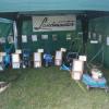
Had a rummage through my boxes and found my tackles that ive collected over the years ( don't know why ) but here's some photos. -
1 point
Give us a Lift
Triumph66 reacted to the showman for a post in a topic
As I advance into my mature years I'm finding it harder to pick-up engines and transmissions so i'm looking at making these things easier without spending any money. I'm looking at making an engine hoist or gantry and was wondering the +s and -s are between them -
1 point
-
1 point
Wheel Horse RJ-58 Restoration
Cub Cadet reacted to pmackellow for a post in a topic
Looking great mate -
1 point
Wheel Horse RJ-58 Restoration
Cub Cadet reacted to the showman for a post in a topic
Looking better now you've got some red bits, -
1 pointAnother good job and another step nearer the end result.
-
1 pointAnother neat job and a good idea with the wheel studs/nuts.
-
1 point
Give us a Lift
the showman reacted to Cub Cadet for a post in a topic
Nice work! Going to be very useful. -
1 pointWhile walking into town, my usual Saturday excitement, I detour through a small trading estate to have a peek in the local metal fabricators scrap bin. Most weeks either nearly empty or full of RSJ off cuts and 4" or larger thick wall box section plus large section angle. All big and heavy. Last Saturday had a much better assortment of small stuff mixed in with bits of the above plus other mixed junk including lots of tangled metal banding from delivery's of steel. Back today with the car. Into the shop / office and asked if I could have a dig in the bin. Lady person at desk didn't sound too keen. "We don't like that" but donned a high vis vest and came out into the yard. I pointed out a few smaller section bits and asked if I could have those. "Yes, but be careful, there are lots of sharp edges", as if I didn't know. Started pulling bits out and she started helping. I think she was worried in case I cut myself and sued. She would have had a fit if she had been at John's place while Chris and I were clearing the scrap. Anyway, got a selection for possible future use. Would have dug deeper and got more if lady person hadn't been nearly having kitten's. Asked how much I owed, "Nothing" was the reply I was hoping for. Result, although I was prepared to cough up a few tea bags. Various sizes from 2" x 1" down to 1/2" square plus round tube and bar, flat strip 1/4" thick and an 18" x 12" x 1/8" plate.
-
1 point
Give us a Lift
HeadExam reacted to the showman for a post in a topic
I could have parked it on Pam's lawn and put the dipper arm through the window . Thats a good idea. I want something more manoeuvrable than that Mark -
1 point

Give us a Lift
Triumph66 reacted to meadowfield for a post in a topic
That's why I built a hoist, makes life a lot easier. Hoist was £30 off that auction site. -
1 pointBit late now but you could have used John's digger as a hoist with the grubber fitted instead of the bucket. Grubber would fit through the shed door and be easier to hook things onto.
-
1 pointThe original exhaust which.was used for the test runs was unsuitable for scale appearance and was also in the wrong position. A 180 degree bend to fit within the side panels was needed. I tried a length of flexi pipe I had but this wouldn't bend into a tight enough radius. A piece of 15mm copper pipe was bent up using an ancient and crude pipe bender ( found at friend John's place ) where else, which gave the required result. The exhaust stub on the engine is approx 22mm outside diameter although the bore is a lot smaller. An adapter was turned up to suit. During the clear out at John's various stainless steel silencers were found which John had made at work. This one was removed from a mower and cleaned up. This was connected to the copper pipe via an old 90 degree plumbing elbow after cleaning off all the muck. After finding a length of chrome plated pipe a posher version was bent up. No prizes for guessing where these came from. Not sure how this pipe and the plating will stand up to the heat but not the end of the world if it doesn't. An extension was made for the silencer, again from copper pipe, as I didn't have anything else of a suitable diameter. This was drilled and the lower end plugged as per the full size. An adapter ring was turned up, drilled and tapped to hold everything together. This ring also located the assembly into the grill surround. The completed parts and after fitting. Still need to make some adjustments.
-
1 pointGreat workmanship and thought going into this project Ian, grand job. I hate to say this but, in the photo of your driveshaft, it looks like the shaft yokes are out of phase. All shafts I've had dealings with, (apart from steering shafts installed at high angles, which don't spin at high speed), always have the shaft inner yokes in line to aid in cancelling out vibrations, not a problem if the whole assembly runs in a dead straight line, but when angles are involved? Not a criticism , just an observation . You don't want that coming adrift at any speed close to your leg The ideal perhaps, would be a pair of CV joints, if there's room.
-
1 pointNot much to report, Monday was spent arguing with a car radio, and yesterday my knees were so bad I was only in the workshop for a little while.. But I did manage to get the front driveshaft welded up.. I don't think the welds are going to break Almost forgot, the latest MadTrax video... Enjoy
-
1 pointTo get the drive from the Honda bike gearbox to the TB I had to find a way of turning the drive direction around by 90'd.. One of the steering UJ's fitted with the the splined section from the original CX/trike propshaft.. The shaft will run diagonally between the engine and TB with a nice meaty bearing to hold it in place. And via this double UJ thingy the drive will come out the side of the frame through another meaty bearing and put the drive in the same orientation as the TB input shaft.. Working out space for the TB to front drive shaft. Using a mixture of different shafts and UJ's there is plenty of space to run the front drive up the side of the engine. Hhhmm... Maybe not quite the same size where they need to be joined! A bit of lathe work later.. Ta-Daa Not fully fitted together in this photo as I don't know the exact length yet, but you get the idea Popping back around to the other side of MadTrax for a mo, the pulley (I will be using chain and sprockets) is about the right size to give me an idea how much space I need to create to fit a bearing in. I need to slice some of the frame out here, but I planned to do that anyway to get rid of the un-needed swing arm mount.. It's the only bit left that says "I've welded a few extra tubes to a bike frame" The bearings arrived Wednesday but I've not had a chance to do anything with them.. That's fun for tomorrow