Leaderboard


Popular Content
Showing content with the highest reputation on 02/09/2019 in all areas
-
3 points

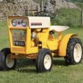
1973 Bolens G10
Triumph66 and 2 others reacted to Joseph for a post in a topic
We got our 1973 Bolens G10 out of storage to check it over and see what parts it needs. We bought this tractor as a non-runner 18 months ago and so far we have not done anything with it. A previous owner has modified it to take a Westwood blade. It must be an early one as the serial number is very low. A quick video introduction -
1 point

A Mystery Roaring Twenties Refurb.......hopefully!
Cub Cadet reacted to Anglo Traction for a post in a topic
Well, perhaps just a subdued British 1920s refurb ! I'm hoping I'm not tempting fate here by starting this before I am confident it can be saved and bring back to working order, but I have reached a point where I am reasonably confident. The intention is not just to keep this a mystery 'til near the end, but to document the challenges of working on what can only be described as an old garden sculpture that used to be a machine. I reckon that this machine had a useful life of about 7- 10 years from early 1922. Thereafter, it was abandoned and left outside for at least 20 years with only the oil laden dirt to protect it. It had later (in the mid 50s) been moved to inside an old van and stored there until it saw the light of day back in Sept 18. Always been in the original purchaser's family possession until then. Being of the ilk that likes a challenge, this may be harder than I've been used to in the past. The engine is obsolete and I have no parts information for it, or the machine's frame. I have acquired some excellent info on the engine and carburettor and has allowed me to progress with checking wear tolerances and set up. I make no apologies for all the detail in the thread, as I hope it may be of use to anyone who also attempts to tackle an old Villiers engine etc. Work began on the engine to see if it was salvageable. This is the Villiers MkV 269cc 2 stroke of 1922. It is the engine version that was first to use the flywheel magneto patented around 1920 by Villiers. Very simple and effective at that time- Known as the large flywheel type Magneto (8 1/2" dia or 216mm), the engine had undergone several revisions since it's inception in 1913. Designed originally for motor bicycles, this one has a variable timing Armature back plate, but has no use for this machine's application, as the ignition timing is for TDC!. Flywheel is matched to this Armature Plate having identical numbers stamped on them. Condition of the engine externally was badly corroded Fins etc on most upper parts, as you will see in various pics. Internally was pretty dirty and no evidence of ever having been de-carbonised as it had a very thick layer inside the piston. Obviously the rings were seized after about 80 years- This engine, being very early 1922 was still fitted with 3 Rings. Later 1922 engines appear to have only 2 at the top?. Production of this engine ceased in September of '22' . I had suspected the wear in this engine to be quite bad, as it was designed to be upright and not horiziontally mounted, but was surprised that it was reasonably good as cleaning progressed. Years of oily dirt helped to keep the corrosion down in certain areas which can be seen in this pic- Note:- the chain was fitted to provide restraint while undoing the Crankshaft nut to remove the Fan. Once the engine was liberated from the frame, the internals were dismantled. Piston gudgeon (wrist pin) pin is the 'Drive In/Out' type and locked with Cotter/Spit pins. With this removed I found serious wear to the pin and con rod 'Small End' bushing. The cause being no oil hole visible to allow lubrication!. Having been blessed with access to a donor engine of the later type (2 piston rings), I obtained a good and little worn gudgeon pin, but had no option other than to make a new 'small end' bushing. I put that to one side while further evaluation was made. Cylinder and it's bore was cleaned and looked quite good considering and maybe just a hone required. Despite virtually no scoring in the bore or the ring faces, the wear limit of the ring gap is excessive and really needs new ones and a hone. Piston is good. Donor engine bore etc are poor condition. Valuable information came by the way of old editions of 2 different books by motor cycle enthusiasts of the 30s onwards, namely Cyril Grange & B.E Browning. Between the two books, I was able to extract all the max wear tolerances and most procedures. I did have a problem finding the best way to remove the large brass retaining disc/washer that retained the Armature Plate. It also appeared distorted or cup shaped - I was also concerned about the wear marks from the Flywheel on the armature plate's face, just visible top L/R of pic above. Disc/washer was a press fit onto the Crankshaft, so I went carefully and used 2 small levers to evenly prize it away with the expectation of finding an oil seal of some type behind it, only to find nothing!. Never had any oil seal fitted and no sign of leaks etc!!, all metal running fits. I reckon the cup shaped look of the washer was from strain of some kind and should be flat?. At the same time, I had fears of the Lock Screw at the back of the Plate being totally seized, as it only has a screwdriver slot, or what was left of it- I found the heftiest flat bladed lever I could use and to my surprise after a little of my releasing fluid, it unscrewed smoothly and the plate could be removed exposing the corrosion and rot- The list of jobs was gradually increasing the more I delved, and the damage from it's last runs was appearing. I tested the HT Coil using ohms resistance just to endorse it was dead, found there was still continuity in the 2nd winding, but only had half of the normal resistance. Going new anyway. modern version of this pre WW2 HT Coil is available, as well as the HT Lead, but not cheap. So by this point, I knew what was needed, what could be done and obtained to get this running again. ......soon to be cont'd. -
1 pointAbsolutely fantastic job! Definitely something to be proud of
-
1 pointMany thanks for the information it is heavy LOL but I was given both the blue ones and the red one a few years back. I did get one running but due a major house renovation they have sat on the back burner for a while but th information you have given me is a big help and inspiration as well as the photos on here of course. Is TSP a thinners solvent ?
-
1 pointThat is a Homelite C-51, made between 1964-1967. Here is some information http://www.acresinternet.com/cscc.nsf/ed1d619968136da688256af40002b8f7/b7dfa302dafd0c9188256b7c001833a1?OpenDocument Parts are still easily attainable. The C stood for convertible because these saws often were used as power plants for post hole augers, ice augers, power generators and water pumps, they also had a clutch attachment to change from a direct drive chain to a gear reduction chain. These C series saw were way overbuilt structural and while heavy for the hp, were reliable over many more years than most saws. The C-51 was 77 cc's, the larger C-71 was 80.5 cc's and the C-91 was 85.5 cc's. Sand blasting with walnut hulls will prep the saw for paint and I recommend a cleaning in a alkaline based cleaner such as TSP or equivalent.
-
1 pointMany thanks for the info and here is a photo of my sad little collection that I hope to get on with later in the year
-
1 pointI doubt if there is any book or literature on restoring saws. I collected over 40 old Homelite chainsaws and over 100 Homelite chainsaw manuals, then collected new spare parts for all of them. Cleaning and paint prep on magnesium is different than other metals, but painting a 2 stroke machine that needs to be gas and oil resistant requires a epoxy clear top coat.
-
1 pointFound this https://www.amazon.co.uk/Buckbock-16100-ZF2-V01-Carburetor-16100-ZF6-V01-16100-ZF6-V00/dp/B07KQ6X9J1/ref=sr_1_7?ie=UTF8&qid=1549663344&sr=8-7&keywords=huayi+carburetor
-
1 pointWow that is stunning!! in fact I think I may have a similar one will check tomorrow in the meantime can anyone point in the direction of how to renovate a chainsaw as I have a couple that need sorting and I need to read up on how best to do this before I start
-
1 point
A Mystery Roaring Twenties Refurb.......hopefully!
Cub Cadet reacted to Anglo Traction for a post in a topic
Having done some swatting up on machining this version of Phosphor Bronze (PB104) and looking for more endorsements that it is the correct stuff for the job, I went ahead. The Gudgeon Pin obtained from the donor engine was a god send, as I had visions of having to make one and pay for the cylindrical grinding and polishing to size. I went all over it with a micrometer, noting and marking sizes. I found a slight taper of 0.0002"(0.0051mm) end to end. The most wear I found was 0.0006" (0.0152mm), so I aimed for closest fit possible to that. Strangely, the pin diameter is neither metric, or imperial and so worked to 0.4915" - Started with 3/4" (19.05mm) dia stock rod. I knew the stuff was a bit 'sticky' when machining. Using 1 part cutting oil and 10 parts White spirit (mineral spirits I believe in U.S) I followed a set process of repeated shallow depth drilling, followed up by boring and progressively enlarging the bore to keep the friction heat down. Stayed only warm to the touch throughout, so was happy with that. Got to 31/64" (0.4843") leaving me about 0.0072" to finish. Moved the part still in the chuck over to the Mill and fitted to the rotary table for marking out and drilling the oil way- You may see on the old bushing, a circle just below the oil way. Well I scribed the circle while it was still in the con rod due no hole visible. It was not until I removed the bushing that I found the oil way there. So either it was originally fitted like that, or it moved round ?. Anyway. after drilling the hole, it was back to the lathe with it to finish the bore to size and turn the outer diameter to a press fit- Put shallow helical groove in the bore for oil distribution, then parted off and finished ready for fitting- A bit of relief to get that part out of the way, so continued to chip away at various bits. Tank Cap was plugged, fuel tap was seized up and clogged. Also has a filter in the lower section. All cleaned ready. The back of the Armature Plate lightly cleaned to keep the age look and proceeded to make the rusted, rotted parts. Spring wire HT cap retainer and the armature plate lever. Both Oil blackened and heat treated. New HT Lead and ready now to fit the piston- You may also notice the Lock Screw for the armature plate looks a bit better now. The black markings on the piston are not wear or damage. I believe they are fine grinding marks from when it was either being prepped as a casting ready for machining, or after machining to allow for some skirt clearance and oil retention. Carefully checked and marked the parts for correct orientation and order of assembly, starting with the small end bushing and avoiding any strain on the con rod and bearings- That bushing should not move in a hurry now!. And with another 'pre fit' check, the ceremonial oiling and fitting of the piston - ....................tbc -
1 point
A Mystery Roaring Twenties Refurb.......hopefully!
Cub Cadet reacted to Anglo Traction for a post in a topic
No Norm, I would not dare to do a blind 2 stroke cylinder with large transfer ports. Don't have the gear. It should be done properly on a machine that limits the oscillating travel of the rotating (multi) stones at the right point and that the stones can't catch on the ports. It should only really be done when the bore can be measured accurately to fit new rings so end clearance is minimal. This bore surprisingly only had staining with no rust pitting or scoring, despite the engine being locked solid until my releasing fluid did the job and freed it up. Thought I had a pic of the cleaned up bore, but can only find this one from after removing the cylinder- I was really quite impressed with the smoothness of the cleaned up bore and struggled to find any wear lips or tram lines. I think the low skirt piston ring served to maintain even bore wear and prevented piston slap wear. The single replacement ring will have to bed in as is, but will be assisted with increase of Petroil ratio and 40 weight oil instead of 30 wt. I was not happy with my attempts to clean the crank case out as much as possible without splitting the cases. After several attempts to remove the drive sprocket from the Crank, I gave up. It is worn, but serviceable for now and I could not position it in my 12 ton press to apply correct force properly without risk of strain or damage to it. So I split the cases which showed the cleaning limit lines- Just as well I split them, as the oil galleries to the Crank bushings were solidly blocked with carbon, as well as the surfaces . Armed with a few old toothbrushes etc, it all cleaned up nicely and very smooth shiny surfaces at the contact points. Next pic shows that this engine was designed to run with the cylinder vertically. The recessed valleys each side above the shaft bushings collect and channel oil to the galleries for lubrication. They can't do that so well when it's in a horizontal plane. The other point is that the crank case drain plug is rendered useless!. Another observation is the design of a separate lubrication facility where oil is passed into the crankcase via a hollow mounting stud or bolt, you can see the recess around the bolt hole in lower left and right positions of the case halves in the pic below- The separate oil system is not used on this application, so uses premixed petrol and oil (petroil). I checked the crankshaft end float before splitting the cases (0.0055" or 0.15mm), it's well within limits, so I measured the old washer (gasket) thickness and cut out a new one. Quality brown paper was used with a thickness of 0.0045". Thought I'd stick to tradition and use shellac to dress the washer/gasket and bolted up the cases. Left to set overnight, tweaked the bolts and checked the end float and got 0.006" . Real happy with that, so gave it some oil in the important bits. Now that it was all clean, I could check the wear limits of the crank bushings. up, down, left and right movement on both sides using about 20 ft lbs (27.12 Nm) pressure. Flywheel side was good with only around 0.005" in all points. Drive side was a bit excessive on the chain strain line (0.010") , but good up down and right. Just as well as only option would be to make new one(s)......no thanks!. Established the type of bronze I needed and ordered some PB104................................... TB Cont'd . -
1 pointJust in case anyone is wondering, progress came to a halt after Christmas, due too a refurbishment of the kitchen. This meant the workshop became a storage/assembly shop. And as stuff went into the house, things came out and into the workshop. Hopefully all will change, in the workshop at least, this weekend and I can get back to the tractor and normality.
-
1 point
A Mystery Roaring Twenties Refurb.......hopefully!
Cub Cadet reacted to Anglo Traction for a post in a topic
Well, I hope it provides some reading entertainment for you Gents. Afraid a simple 'Oily Rag' refurb has escaped me again Norm. The cylinder had to have the various bits removed from it. Luckily, the completely blocked Decompression Valve relented ok and the bypass tube plug in the head undid, but the eroded exhaust flange nuts had to be cut and split- While still dealing with the Cylinder bits, I had to start searching for somewhere to have new Rings made. A few hours interweb searching later, I'd found reference to a restoration of a 1922 CWS Federal Motor bicycle. It had the same engine as this one and reference was made to an engineering firm that did all the work including making new Rings!. So I fired off an enquiry and received a good reply with price estimates for each item of work, i.e, a cylinder hone and 3 piston rings to fit. Long story short, I built a strong protective box to transport the parts and to return them in it- Disappointed to say the least after receiving an email saying 'all done' and sorry for the cost/charge as was more difficult than he expected!. When it arrived, all they had done was to make one piston ring!. They left the 2 old rings on which I sent for their pattern reference, did not hone the bore and charged double for one ring. So with fingers burnt again (as some here will know) from remote commission work, despite endorsements, my faith in British engineering firms has diminished completely and will now only deal with 'face to face' arrangements. No option but to proceed and have faith that the wear, although greater than stated limits, will be ok for it to run ok. The point being that it has been fully de carbonised and so loses some assistance the carbon can offer in compression retention. Onward's we go, and started the servicing of the De-Comp valve. Solid with carbon and parts rusted away. Cleaned up and made new clamping screw for the lever pivot collar and pivot pin- Valve seat and face cleaned up ok and only needed lapping with scrapings from p600 emery and 'T' cut. New valve nut, 1/16" cotter/split pin and will have new copper washer. Lever pivot hole egg shaped, so bored it out larger and fitted a bronze bush (not in pic). Next job was to obtain the correct type of bronze rod for the small end bushing................................... T B Cont'd -
1 pointThink I am near the end of this project now, apart from sorting teething problems out. During runs at last years shows, the clutch to gearbox drive chain kept locking up. The original chain tensioner wasn't up to the job. This has now been changed but not yet tested. Fingers crossed. There is still too much free play in some of the steering joints. Still working on how to overcome this. Mark ( meadowfield ) made up the decals. Thanks Mark. Couldn't get good photo's in my garage. Too many reflections etc with or without flash which also shows up dust specs. Need to retake in daylight, as and when. Dummy light and ignition switches were fitted but think the key could be slightly larger. A few more taken at the shows. And the almost finished trailer. Finally, the tractor needed someone to drive it while I just sat and enjoyed the scenery while being dragged behind. Hours of searching for a suitable size person resulted in nothing. As I wasn't allowed to borrow my 15 month old great grandson, ( he would have been cable tied on to stop him falling off ), the next best thing was to make something up. A head was obtained from China. Cheap as usual but a bit pink looking. His face was weathered, well he is a farm boy, using some of my old modelling paints which were well past the sell by date Some people say he is a little too brown, but he doe's get out in the sun a lot. An ice cream tub, wood, foam and tape were used to bring him to life. My great grandson donated some of his clothes. Calvin, that's his name, was knocked up in a hurry just before the shows, and had to make do with rough and ready gloves and hat until something better comes along. Here he is having fun and being followed by a Doc Brown ( from Back to the Future ) look a like. Don't all laugh at once. As said above, I think this just about wraps this project up, apart from a few modifications and better photo's of the decals. What next ? Watch this space. PS. Calvin had to wear sunglasses when looking at his passenger.
-
1 pointGot a bit more done today. Engine back on and engine covers fitted, along with the recon carb off Anglo Traction. I have found there's still a slight trace of a leak from the sump. So I think I'll have to find a replacement.
-
1 pointManaged to get quite a bit done today. One or two hiccups, but a good day. Got the engine painted this morning and the paint dried quite quickly. By lunch time it was back in place. Next I fitted the drive belt and this was when I hit problem number one. As you can see in the photo', the bottom run is under the brake pedal. Should be over the top. So foot plate had to be loosened, the pedal moved out and the operating rod disconnected from the pedal. Got that correct and moved on to the P.T.O. This provided a little snag, as the support bar would not connect to the pulley spindle. Cured that by taking everything off again and moving the drive pulley further in. It wasn't quite fully on by about 1/16". Just enough to prevent support bar connecting with the shaft. All OK now. Fuel pump is now refitted along with governor linkage. Finally I thought it a good idea to fill the engine with oil, which I duly did. After which I did a bit of tidying up before returning to the tractor. Then I SAW IT. A big puddle of oil under the tractor. The C-125 has a tube attached to where the drain plug would be. I'd forgotten to fit it.