| |
-
Your right, only one complete trimmer seems to have been found and there were three engines sold ePay from someone that acquired them when AEP closed down, they got re-sold by a trader on ePay & CNew bought one of them. The trader put an incorrect 13A starter on one of them too , did anyone buy that one?
They were made in the last few years of AEP, probably not many got sold* and hence little to do with these trimmers has survived.
*I would imagine most of them got put in the trash once AEP closed down & parts became unobtainable.
David
-
Looks very nice, I've got one of these where the tank has rotted through, but I've seen one for sale.
David
-
Only the parts shown in post #23 on the previous page, plus a few other unidentified spacers & fittings, I'm on the look out for used trimmer parts from other brands that may do for the trimmer head.
I've got most parts for the engine, apart from a series 13B type starter (may have to use one from another engine till I can find another), also need to repair another magneto coil.
David
-
A bit of progress on the trimmer engine build.
Here is the crankcase after cleaning together with the NOS Tillotson carb & induction housing.
I found some brass tubing for the crankcase pulsation port, the tubing is from a scrap wafer switch (which had been drowned along the the item it came from), luckily it's a very close fit to the hole in the crankcase.
To fit the tubing I used a blowtorch to heat up crankcase to expand the hole & allow the tube (cold) to be pushed enough to for an interference fit once everything cooled down.
A cut-off wheel in the Dremel cut the tube down in size and the internal & external edges were de-burred, I had to clean the crankcase second time to remove oil & swarf.
Fuel line fits perfect, need to order some more though.
David
-
Good to hear it worked out.
David
-
It must have been a small pump something like that, probably taken apart & thrown out when the rubber impeller failed & it stopped working, there was a Comet pump sold recently with the pump missing too.
David
-
I took some pictures earlier today to show the technique I use to join the wires & leads of the diodes together, I'll get them edited & uploaded tomorrow as it's quite late now.
David
Here is how I made the join for the wiring in my TT, demonstrated with wire from a scrap wiring loom, the technique used for the wire loops dates back a very long time, I first saw it used in a pre-war radio for joining multiple wires & components together (before printed circuit boards existed).
The wires before & after tinning with fresh tin/lead solder (note: do not tin wires if using crimp or wire-nut connections).
To make the loops I use standard tinned copper wire (aka fuse wire), I have a few different wire gauges for joining different thickness cables, choose a drill bit or something else that is a bit larger than the cables to be joined, wrap a few turns of the tinned copper wire around & cut to length.
I've shown a couple of sizes I made and if you leave a length a wire as shown they can be used in other things for extending component leads. Slide the loop over the tinned wires to be joined (for a continuous length of wire slide the sleeving on before soldering).
The whole lot soldered together with tin/lead solder and here are some finished joins ready for sleeving.
Hopefully this will be useful to others.
David
-
I took some pictures earlier today to show the technique I use to join the wires & leads of the diodes together, I'll get them edited & uploaded tomorrow as it's quite late now.
David
-
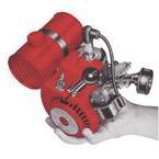
One of the LIFESAVR branded versions of this generator just sold on ePay, sadly missing the pump, but you can see how it would attach, an extra bracket is fitted to the generator housing & the plastic cover removed for fitting the pump to the alternator shaft.
David
-
I'll move the others later tonight, I've sent you my email address for any other manuals you would like adding to the forum, thank you for taking the time to scan them.
Edit: All six Octura brochures are now in Section 4 of the Manuals/Brochures thread;
David
-
That is indeed just the year of the last change to the instructions, at the time your engine was made. The serial number confirms the date of production of the engine as being Jan 1975, 13B is the series of engine & 352 is the engine spec.
It's interesting to see it's branded O&R, the first adverts with the new name of Advanced Engine Products Inc. (AEP) appeared in Dec 1974, it looks like the factory carried on using up parts with the old brand first.
David
-
That's how it was when I bought it, it could be pigmented varnish similar to what we used at work for traction motors, but is probably just lower cost red paint. Rather annoyingly they painted over the wire colours, but this isn't too much of a problem as measuring the resistance confirms which windings are which.
Yours just has lacquer on the coil wire, but it does allow you to see the sleeved connections to the coils better.
The corrosion of the copper is due to chemical reaction to the rubber insulation, copper wire used is normally tinned to prevent this, nothing else on your TT looks rusty/corroded. If you look at mine the socket clamp & diodes were very rusty.
David
-
I've just moved the first one, @Daren89 please let us know if your stored data has gone down.
I always add credit for any contributions to the manuals thread, also just added one for the Wards Digger manual you added.
David
-
It might be screwed down to the crankcase flange which would still work, the wire looks quite short, the later tools often have it mounted on the the cylinder cooling baffle/plate above the coil, needs a longer wire for that though.
I think it is too because of the engine date, but can't confirm the label says that as it's not clear.
BTW there are black labels for both O&R & AEP branded engines.
David
-
These are a little tricky to work on, they come apart & go back together in a certain order, I'm still looking for a manual to add to the forum.
It's quite a bit newer than 1967, engine SN 501xxxx was built in Jan 1975, also the engines weren't called the series 13A or 13B till Sept 1970, does the label on the top of the starter say Ohlsson & Rice or Advanced Engine Products Inc? I reckon it could be the latter.
The later carbs have a brass check valve which often gets stuck with old dried out fuel mix, also they can have the rubber seal for the arm inside the diaphragm assembly, these also go bad. The diaphragm will need changing if it's hard & brittle.
The intermittent spark could be the points needing cleaning or a loose/bad connection somewhere.
David
P.S. nice to see one of these drills that still has the chuck key with it.
-
Those wire nuts aren't used much in the UK and the crimps originally used would need expensive tooling for a reliable connection.
I'm not sure if it shows in the picture, but I make a ring out of solid tinned copper wire to use for the soldered connections, then put the wires in this before soldering, it helps make a much stronger connection, I can take some pictures if needed.
Also they may be a pain to solder if you don't clean the tarnish from the wire ends before soldering.
Two layers of slightly larger heat-shrink sleeving cover the join, use a longer piece for the first layer & fold it back on itself back before sliding the second piece on and this will cover the exposed end.
David
-
John, I'm going to add the brochure pdf's to the manual thread, would it be best if I removed them from the other threads as they have used up all Daren's free storage space a lot quicker than normal.
David
-
Oh dear, the wires with old crumbly perished rubber insulation, the last one I worked on was so bad I ended up sleeving all of the alternator wires with heat-shrink tubing. The wiring for the 110V outlet isn't made from rubber & didn't need sleeving.
David
-
There are gaps in the service bulletins I have, that must be one of the missing ones, also I have none later than SE103.
The only double I've seen so far is the one on Webhead's Orline Chromer chainsaw;
David
-
That's exactly what I'm going to use it for, I have a NOS Tillotson carb from Webhead and the correct induction housing to fit it to the crankcase I just found, it's saved me having to modify one of the complete engines from my collection, I'm going to see if I can build the engine from my spares, I think I have everything apart from the later style starter.
The pictures of your engine are a great help to see which parts are used.
David
-
Well I think I've found why that O&R double diaphragm pump assembly isn't seen, it's part no. #400016 which is shown on some parts list dating from Jan 1970.
It looks to have been quietly dropped from use, as the master price list supplement from Apr 1971 says to use part no. #400175 (no description of the part), but I found a picture of this part I saved from the web and surprise surprise it's a standard diaphragm pump assembly.
David
-
See post #6 on the previous page, it's for the tube going to the fuel pump on the Tillotson carb which uses pulses from the crankcase.
It's possibly also used for the rarely seen O&R carb with the double diaphragm (anyone got one they want to sell?), maybe most got converted back to a standard carb & the hole blocked up.
By the way I found a second crankcase with the same blocked port, at least one of them looks to have come from a chainsaw.
David
-
I've had a TT400 on the back burner for a very long time, the engine got rebuilt but I now can't get to the lathe to machine a new screw for the alternator, it's longer the standard TT uses BTW.
I've been busy with selling & packing things (non-O&R related) since the last cheap listing weekend on ePay.
David
-
The estimate for this engine is early 1963, that is a nice clean engine which has probably not been run very much or possibly never used.
David
-
Is the second digit of the serial number a 5? The date estimate for this one would be sometime around 1963.
After Oct 1963 the engines had needle bearings for the gudgeon pin & should have steel cages for the bearings (but not always), the primer button was introduced at the same time, but these were available as a kit for fitting to older engines so aren't too helpful for the engine date.
Keep the tank bracket if you remove it, also it could be useful to someone else it you don't want it, I can't quite make out the letter stamped into the other side of the crankcase, this would tell you which type of gearbox was originally fitted, the housing is one side of that gearbox.
David
|
|