| |
-
Laser cut replacement diagrams are available from several forum members in the US including @Wallfish & @Webhead and from me in the UK.
If you haven't already seen it check out the carb rebuild thread and don't forget to replace the old crumbly air filter foam, any other questions feel free to ask & we can help.
Have you got any pictures of your Mity Moe?
David
-
The Groomer string trimmers (weed wacker) were made in the late 1970's by Advanced Engine Products Incorporated (formerly known as O&R), this was towards the end of AEP (O&R) as the company was dissolved in 1978. Hopefully someone will find a complete trimmer one day.
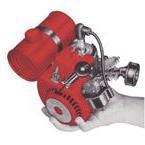
As you've noticed the 13B427 is a constant speed engine using the Tillotson HU38A carb, this is pre-calibrated for constant speed operation only and has no fuel/speed adjustments. The added primer button is for easier starting and the extra tube to the crankcase is to pulse the fuel pump.
I don't recommend looking at a standard parts diagram for the Tillotson carbs as they show all the bits not used on the HU38A, the diagram below is from the book "Small Air-Cooled Engines" 16th edition from Intertec Publishing, which has a small section for O&R/AEP engines, I don't want to add the rest as the current version of this book is still available and I don't want copyright problems.
The air filter would have been on the end of the tubing that made up the pole & handle for these trimmers, the engine stop/kill switch would have been on this handle too. Some models had another tube with handle used as the gas tank and others had a gas tank attached to the starter housing.
The trigger mentioned on the decal is indeed for releasing more cutting line on the trimmer head, they called this a "Touch-n-go" trigger. Other models had a "Bounce-N-Feed" trimmer head, this version released more cutting line when lightly bumped on the ground.
David
-
The keys and the taper are the same. The shaft that was in that engine is for a different style engine and therefore it's longer. Plus it was only one side of a different shaft I believe. The other side was right or at least it works perfectly fine. I believe it's because the engine I have uses the plastic bearing cages and that longer shaft is from and engine with the newer roller bearing and 2 washers on the side. This is exactly where David always shines as he could probably provide exact part #s, exact measurements, which engines, DOM, ect. ect. That guy is incredible!
I've found a possible match for the slightly longer backshaft in the April 1964 parts list, it gives gives 42-12 as the backshaft without keyways (used after SN #006072) and 42-18 as the same backshaft for use with A-131-4 thrust bearing assembly. However this assembly is neither shown on the diagram or given a separate number/entry in the parts list and no mention if any other parts are changed to use the thrust bearing either.
Also the 1971 price list states 42-12 (without keyways) use 42-16, which is the same shaft but with keyways.
Anyone else confused, I certainly am.
David
PS I need to check the 1961 to 1963 info that isn't scanned too.
-
I will need to do more research to check about the thrust washers, adding a picture will help confirm which ones you are thinking of too.
David
-
Looking good, I've been thinking all of these covers need reinforcing with glass fibre matting like that.
Would you like me to change the title to "spring project" and maybe add Aquabug too?
David
-
Actually $365 at current rates, plus the cost of a new chain, the missing vertical gas tank and another donor engine if needed.
David
-
By the way the 1971 price list fails to mention* anything about the A-27-11 main con-rod bearing change to A-20-5-13-7, that must be used with a slotted con-rod and also a change of piston & wrist pin, here is the April 1964 parts list information;
From the August 1964 parts list, the con-rod main bearing was changed to A-20-5-16-7 with 7-25 washers.
David
*Which is why it takes a long time to cross check to find the correct information, also note you will find more bearing differences with engines below SN 006072.
-
A couple of sources (1971 price list & 1965 parts list) give the following bearing changes, of course it all depends on the age of the engine as to which are used, the changes started happening around 1963/64 following the NIAE test report;
Crankshaft main* bearing: A-27-4 use A-27-17.
*When they changed the crankshaft main bearings in August 1964 they used part no A-27-8 for this one, for A-27-8 use A-27-16.
Backshaft (PTO) reed* & induction housing bearings (2 sets): A-27-2 use A-27-18.
*When they changed the PTO shaft reed valve bearings in August 1964 they used part no A-27-4 for this one (1 set), again A-27-4 use A-27-17.
The A-27-3 bearing never changed part number for both the plastic & steel cages, I did note the steel cages are slightly thicker than the plastic ones, this may have been because they were used of course (it was a while ago I checked).
David
-
I thought you had bought a manual some time ago when you first found the Clinton, as there were several available both on ePay & SCamazon at the time I ended up buying one too.
In fact there must be more manuals than surviving outboards.
David
-
£280 if you believe the seller, I don't.
A lot of O&R tools in the UK are in that condition, but because these chainsaws are not common it would have still been worth restoring, even if that meant replacing the engine, FYI mine isn't much better.
David
-
The handle grips are often missing on these drills.
If you haven't seen it I posted the manual a while back here (section 4);
Shame it doesn't give individual part numbers for the bearings & seals.
David
-
Well the bad news is I can't buy it for anyone either, apparently it was sold on Saturday for a silly price.
David
-
-
I wouldn't worry too much, you've probably eaten plenty of food that has been sprayed with these chemicals over the years.
Did it look as bad as mine? Which was also very rusty & corroded too, which may have contributed to the blade being a PITA to remove.
David
-
I'll let you off, Clint mentioned the bearings first.
David
-
You must have done a swap with Clint with the tank & housing.
Decals look very good, it will possibly be the only British branded Aquabug in the US, by the way those Perry decals were stuck straight over the top of the US Aquabug decal.
David
-
Correct torque tightening is very important, we had someone injure themselves when a flywheel came off, not sure what they were doing but I suspect the starter housing was not attached.
They changed the flywheel keys from steel to aluminium for later engines (again the sizes are different) this would allow the key to shear off & prevent keyway damage if the flywheel became loose.
David
-
Already off topic, oh well.
They did use metal bearing cages in the late production model plane engines that preceded the Compact range, must have been a crap cost cutting idea to use the plastic ones, they also seem to swell up which may be the reason they destroy themselves.
David
-
I hope he knows that the shaft seals are different in these early engines.
The carb with the red needle valve, I'm sure I seen that on the Creme Lure generator, mine doesn't use a Type 115 117 though.
David
-
I remember finding a flywheel like that with some parts engines I bought, it would be interesting to see if the crankshaft is different too.
David
-
Both the rubber seal used on the carb diaphragm arm & the brass check valve are commonly found on later production engines, it has very little to do with the application (though one or two later tools did use different carbs).
David
-
It's the standard Compact III 1HP decal as shown below, I can't guarantee it but I may have one I can scan.
David
-
That is very odd, the shaft on my TT Model 400 doesn't look any different from other TT engines as far as I can tell, I need to have a closer look but I think only the tapered part sticks out (on your engine part of the parallel section also sticks out).
Did yours have one of these bodged sections of stud with a nut riveted on, holding the armature on?
This part is longer than the standard Model 300 TT.
David
-
The Type 186 is used on my Turbair sprayers too, sadly the service manual lacks a parts list for it, but does have the type 176 (I have a pump with a type 176), the differences are going to be the type of gas tank supplied, the mounting flange with the extra threaded holes and the carb parts used (they also remove unused parts from these lists).
I also have an engine from a later 13B version, this one is a Type 13B338, the sprayers should have a choke lever label on the large cylinder cooling baffle.
And finally everyone of these sprayers I've seen has the spring removed form the carb idle screw, which is then screwed all the way in, as shown in the manual too.
David
-
The only fuel filter should be in the gas tank, early engines had another fuel filter in the carb, which was found to clog so often that they removed it.
The first one of those check valves I came across was stuck too, all my usual cleaning methods failed, but several KW of ultrasonic cleaning* at work fixed it.
David
*Sadly the ultrasonic cleaner at work was removed a few years ago, as they wanted the space for other work.
|
|