Turning brakes. I was undecided on these. Should I fit them, or not. OK, I'll make a start. Bent up a pair from alloy using photo's and guesswork as a size guide. The levers ? were from 1/8" x 1/4" brass drilled and tapped 8BA. Each lever was made in two parts as attempts to bend as per the full size resulted in a break. Brass too hard. Should have tried heating up first. These levers are probably a bit narrow, 3/8" would have been better but nothing in stock.
It was then decided to leave them for now and carry on with other bits and pieces. Lots of bits and pieces later, Iain slf-uk my head information provider, sent me photo's and measurements of the assembly so a restart was made. My original guesstimated alloy pedals were correct in height and the inside of the bent up lips, much to my surprise, but 1/4" short in length. This 1/4" is the model size measurement. Two new pedals were made and the horizontal brass section extended using a piece of plastic for quickness.
A test assembly.
All these parts were held together with 8BA countersunk bolts. Looks a bit messy on the photo's but all hidden later. A few holes were drilled in the wrong place, but not seen when finished. The pivot bar is brass tube with a plastic insert and a 3mm threaded rod. All bits which just happened to fit together without much work. The lower ends of the uprights were drilled and tapped to suit the rod and the tube notched to take the inner upright. Easier than making the tube in sections as per the full size, and as these pedals won't be working, a bit stronger. The locking bar was also fixed in position. The notch in the tube was later filled and blended in. Various other areas had the same treatment to tidy things up.
The brake pull rods! were from alloy angle , bolted to the underside of the footrest for extra strength with the nearly visible end trimmed down. I had to alter my original footrest support and lay it flat with the alloy angles notched to clear, but as usual after doing all this a better and simpler solution popped up in my head, but leaving as it is. Photo below is before cutting notches for support clearance.
The full size has a steel bar running diagonally under the footrest, from the outer end of the pivot tube to the chassis frame, which helps support the tube. I made up a short alloy bracket which is bolted to the support angle in front of the pedals, and to the front underside of the footrest. Not really visible without effort. Hope all this makes sense.
Grip tape was added to the pedals which finished them off as well as hiding all the bolt heads. The footrests also had a covering of the same. This self adhesive tape was listed on eBay as carpet gripper tape. Similar stuff also used for skate boards. I wanted to use ribbed rubber but nothing suitable found. All too thick. The next photo's show various stages of test fits.
I could have left the cranked ends straight on the brake rods ! by moving them closer together, but had previously drilled the footrest and didn't want to waste the holes. Photo below.
The pins connecting the rods to the uprights were made from a bolt, turned down and drilled, then cut to length. The split pins are 1mm diameter. The threaded end was screwed into the alloy rods after tapping and held with a dab of lock tight. A fiddly job inserting the split pins, especially the inner one resulting in chipped paint, now touched up. Might have been easier before fitting to the tractor. Not too happy with the appearance of these split pins. Need tidying up and the loop made smaller. A job for another time.
A few more photo's of the various parts, mounting brackets, footrest support etc plus the unit finally fitted.
Headlights continued. The mount was from alloy sheet. White border painted on. Will look better with a decal fitted. The two holes were the first attempt at mounting the headlights via a bolt through the original painted reflector. After scrapping this idea holes were cut using a large washer as a guide. Easier than expected using a very fine saw but had to take care not to damage the paint too much. Should have thought of plan 2 before painting.
Next are the lights with plastic retaining rings held onto the rim with very small self tappers.
These three photo's show the lights fitted, then the rings painted. Also showing the bulbs which are just a push fit. These appear to look cross eyed on the front view.
As said previously, these lights were worked on over approx one year on and off, trying different idea's etc.
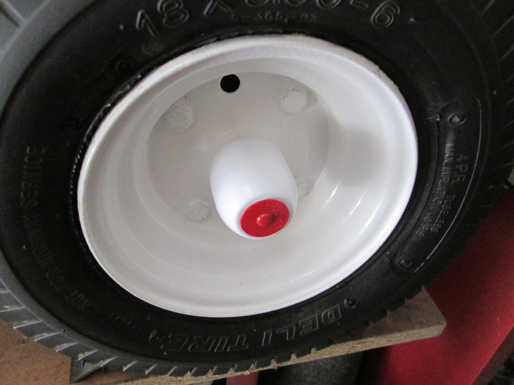
The next photo's show hub caps which were quick and simple and were only made / altered recently. Jumping the gun a bit here but not to worry. Looking around for something suitable the cap from a deoderant bottle was found to be a good fit over the wheel hubs. Black plastic which was painted white. The end didn't have a sharp edge which would have made painting the red easy so plastic discs were cut and fitted using small expanding rivets which I had a stock of.
Three more bottles were obtained which gave the required four. The result, better looking wheel hubs and a nicer smelling wife. OOP's, shouldn't have said that.
The discs mounted on a rod ready for painting.
The four stages and the rivets.
Front and rear wheels with caps. The fronts were a nice push fit but the rears wouldn't go over the hub weld without stretching resulting in chipped paint. A few spots of glue cured this.
J.W. Speaker are a US vehicle light company and made the rubber mounts for standard Par36 units, but I expect you already knew that. Unfortunately they no longer make the originals.
No, didn't know Iain. Reading the posts on Redsquare I had assumed they were surrounds / mounts for noise making speakers. Silly me.
2 hours ago, Stormin said:
Getting there, Alan. Best get a move on though. Only two weeks to go RPT.
All done Norm. Apart from the decals. The above post and others to follow are well behind. I am just bringing the past into the present. Next step the future.
Careful all, don't fall out of your armchairs with shock, I'M BACK. Been a while since I posted but been busy, busy, busy doing lots of little bits, altering other parts, making a trailer plus other non tractor boring jobs.
Now where to start since I stopped. ? More little additions first. The easiest were the lights on the fenders. 2 clear and 2 red were obtained from China, where else, for £6 including post. Hunted everywhere but these were the nearest to the size I wanted. 12/24 volt LED although non working for now. Maybe later. A printed label can be seen though the clear lens which spoils the appearance slightly. Not so obvious through the red. Back and front bonded together so not easy to remove without damage.
The front lights were worked on over approx one year, on and off. Couldn't find anything suitable on the internet. Lots of flat lenses of the right diameter but nothing convex unless I wanted to pay lots of £££'s, which I didn't. Looked at torches, cycle lights etc but again nothing suitable. Tried various ways of moulding them but not happy with the results. Then tried casting in resin using a small quantity which my son had left over from one of his projects.
What to use for a mould. First thought was to make one but looking around my garage the very thing, lots of them, were just sitting there looking at me. Sort of. Spray paint cans. The concave base was almost the correct size. A plastic ring, part of an old magnifier, fitted perfectly into the base of the can and reduced the internal diameter to the required size. The resin was mixed with it's hardener, poured, and left to set. As expected quite a few bubbles were trapped, most close to the outer curved face. These were sanded out with very fine wet and dry paper. Took a long time and finished up with an opaque surface. My son used to buff his castings up with polishing compound but while washing off the sanding sludge I noticed the lens was fairly clear while wet. Opaque again when dry. A coat of clear varnish resulted in a clear lens. Getting somewhere at last. Not perfectly perfect but after all this time, they will do.
The rims were made up from plastic sheet wrapped around a jar lid after increasing the diameter to the required size. Made oversize first then trimmed down. The inside of the outer edge was built up to form a seat for the lens. Still with me ?. The rims on the full size D-series were rubber ? speaker surrounds, probably obtained as the nearest ready made unit. Inspection of these at a show last year showed the word Speaker moulded on the outer surface. This was drawn to my attention by someone on Redsquare who was answering another members query.
Reflectors. Flat plastic discs were tried painted with silver paint. Not bad but wanted something better. More hunting on the internet using all sorts of search words, plus a few of the swearing variety, then up popped these torch reflectors. £2 the pair including post, again from, you guessed it, China. Most small items from China usually take about 14 days to the UK. The larger than required opening at the rear was altered using two plastic discs. One with a tapered edge fitted into the tapered inner edge with the other on the outer face. All bonded together using liquid plastic cement. A 12 volt car bulb fitted a hole drilled through the center. Could be made to work if needed.
The second photo shows the original flat painted reflector disc. The last is of the two discs at the rear clamped together with a nut and bolt while the cement dries. More on these lights next posting.
I used to use Tractol a lot some years back. It's an agricultural enamel. Quick drying and tough. Painted my competition Land Rovers with it. Brush and roller.
Not sure if you can still get it. An alternative is an agricultural enamel called Tor.
Lots of it on eBay, Various colours and quantity's . Approx £20 a litre from most sellers.
Tried bump starting a car with daddy in law years ago. Low battery. Daddy pushing from rear, me pushing next to open door. Jumped in when going fast enough, down with clutch pedal, into gear, pedal released. Nothing. Repeated this a few times then found engine started easily with ignition switched ON.
Pleased that you are on the mend Jonathan. As Norman said, a lot of us are wearing out. Knee's, hips, back ache etc in my case. Just need to look at myself and another bruise appears. I think my next project will be a mobility tractor.
Jonathan (expeatfarmer) and I live about 10-11 miles from each other and are friends from years back.
I'll be exhibiting in the horticultural sections. Wheel Horses. Just ask for Norman. Tall, mature gentleman, Northern accent, white hair and with beard.
Coming soon Norm. Lots of little tractor bits plus a bigger trailer lump.
22 minutes ago, Anglo Traction said:
Can't rush a work of Art Norm . He is probably been beavering away since the workshop warmed up.
Correct Richard. Except that I was also beavering away when the workshop was freezing cold. Were not all softy's down south Norm. Wife did think I was mad though.


") Me, no room to swing a cat.
Me, no room to swing a cat. 
 OK, I'll make a start. Bent up a pair from alloy using photo's and guesswork as a size guide. The levers ? were from 1/8" x 1/4" brass drilled and tapped 8BA. Each lever was made in two parts as attempts to bend as per the full size resulted in a break. Brass too hard. Should have tried heating up first. These levers are probably a bit narrow, 3/8" would have been better but nothing in stock.


 but not seen when finished.
 , bolted to the underside of the footrest for extra strength with the nearly visible end trimmed down. I had to alter my original footrest support and lay it flat with the alloy angles notched to clear, but as usual after doing all this a better and simpler solution popped up in my head, but leaving as it is. Photo below is before cutting notches for support clearance.


 Photo below.


")


 or maybe you can.


 Were not all softy's down south Norm. Wife did think I was mad though.


Rural Past Times, August 11/12
in Upcoming Shows and Events
Posted
Ditto. Except I will be leaving at second light tomorrow morning.") Get the kettle on Chris.
Get the kettle on Chris.