I have just been catching up with your build. Your attention to detail continues to be incredible, love that brake peddle.
Alan if your looking for another job , an option on the D-Series is split wheel brakes with the foot peddles mounted on the other side of the tractor. They would look really cool on your mini-D and they are fitted to my D-200 if you want some pictures, measurments, etc.
Already thinking about this Iajn. Thanks. Have some parts roughed out. Measurements guesstimated from photo's like the other pedal but correct sizes etc would be better. No rush though as working on other parts just now.
2 hours ago, the showman said:
Ha Ha, I think you will need another sheet of paper for your list.
Would a roll of wallpaper be long enough. ? Thought ! If I used a roll of lining paper I could write on both sides.
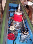
Two little bits this time. The carburetor attachment tube was cut down to about 1/2 length. Left long, the throttle cable was rubbing on the outside of the hood and didn't look good anyway. Cut down, the cable and it's outer spring fitted neatly inside the hood. I expected difficulty cutting the tube down due to the limited room for the hacksaw, but it was a quick and easy job. The tube was softer than thought and a junior hacksaw soon went through it taking care not to mark the paint on the surrounding body panels. The cable is just tucked in out of the way at this stage.
The brake pedal, non working, was made up from alloy, steel washers and plastic. The lettering is 1 mm approx round plastic rod with the curves of the B and R from solder wire. The solder wire was super glued in place with the remainder of the lettering and other parts fused together with liquid plastic cement. The washers, either side of the pivot point, were drilled and tapped then held together with 8BA c/sunk bolts passing through the assembly. The center of the washers, and the plastic/alloy in between, were tapped 5/16 UNF for a mounting bolt which was fixed in place with lock tight. This item was just eyeballed up from various photo's so just a near enough copy. The last photo shows it loosely fixed in place and still waiting final filling and painting.
I'd find that a hard decision to make due to its rarity. Bit big for Chris's lawn, but great for the green and verges I mow.
Bet it will sup the juice though.
Well Norm, if he buys the new and unassembled one too, he needn't make the decision. One for show and one for play. If Pam didn't mind the first, shouldn't be a problem with another.
Like that brake lever / throttle idea even if it does sound like it wants to go and stop at the same time. Could possibly use that arrangement on my Half a Horse / trailer build.
Tried it on the Sears/Roper. The battery on that is slowly losing charge for some reason. After two - th ree weeks standing, will turn engine but not fast enough. Started easily using the pack.
That's what we found too Norm. OK from week to week but needed a boost if left longer. Came off one of John's tractors which he said at the time was a good one. Before that it had a 12 volt 17 amp battery which I used for starting a model boat engine. I think the Roper killed it.
While still at the rear of the tractor, another item which had me head scratching for a long time, was how to provide a support for the steering shaft. As this emerged through the rear panel at an angle due to the differential being in the way, a block of something with an angled hole was required to give more bearing surface than the thin panel.
Could I drill an angled hole in an alloy block without a lot of measuring and setting up. ? NO. I had already looked at various plumb blocks and rose joints on eBay, all being unsuitable for various reasons. Then I remembered some small rose bearings I had found in a box of goodie's while clearing at friend John's. Problem nearly solved.
The first few photo's show an alloy block being bored and the edges milled to tidy it up. The lower inside face was also milled to clear the tow bar. As is often the case, a change of plan meant that I needn't have removed so much metal. Also seen being turned is a reducing bush for the inside of the rose bearing.
The steering shaft is a length of 7mm steel rod. Why 7mm ? Because I had a long length which was originally the drive shaft from an old strimmer I was given years ago. There was already a short 7mm thread on one end, made slightly longer, and a new thread cut on the other end. The bearing block assembly is shown next with the unfinished overlong thread. Overlong to start with as I just eyeballed the squareness of the die to the shaft. If it was out of true after an inch or so, I could cut off and have another go. After a little tweaking of the first few threads and checking at intervals all appeared OK. After threading 3 to 4 inches there was no obvious run out.
I can do small threads using die holders in my Unimat 3 lathe but it would have been a struggle with this especially as the die was not of the split type.
A few nuts were drilled and tapped 7mm.
A 3/8 impact wobble drive socket was obtained to connect the drive shaft to the trailer steering ( when finished ). There appears to be no slop in an impact drive compared to a standard universal joint, but not sure at this stage if there is enough wobble. Time will well. The square plug, drilled and tapped 7mm, was part of the previously scrapped 2 speed drill. Just needed filing down slightly to be a good tight press fit. The front axle end of the shaft uses a 3/8 to 1/4 adaptor with a standard U/J to allow for clearance at the differential.
These last photo's show how little clearance there is between the shaft, axle and gearbox. Approx 3/16th above and below the shaft. Still need to paint the wheels and hubs too.
Don't think Dylan and my great grandson Henry would want to wait for a Mk 2 Chris. Be quicker to build a pair of trailers for them. They both like tractors though, judging by the smiles.
Has Pam seen this photo. ? Chris says he is often out towing, but is he. Could that be just an excuse to visit his new favourite hunting ground. ( Used to be at John's place until recently ) Looks like he is still on the hunt for RED bits.
How to alter the gear lever so that it pointed rearwards instead of to the right as it was when originally fitted to the ride on Bolens mower. The lever was fitted to the top of the box and operated horizontally back and forward but to get the arrangement I needed, ( I had turned the box 90 degrees to line up the input shaft with the engine ) resulting in the selector shaft pointing to the rear. No problem except that the right hand rear wheel and chassis frame would have restricted the lever movement plus access for my hand.
The solution was to cut the lever from it's mounting plate, turn 90 degrees and refix. The idea was to drill and tap the plate, thread the shaft and weld up. Turned out that the plate was extra hard. The center punch lost the fight and I expect the drills would have too. A nut was fitted to the lever to help keep it at right angles to the plate then all welded up. Thanks again Chris.
The first photo shows the original position ( taken after I had cut off and threaded ) followed by the end result.
The long straight of the lever was lined up with the mounting hole in the plate so that when fitted it would be in line with the gearbox shaft. A bit of tweaking was needed later to cancel out slight eccentricity. Hope that sounds right. A photo of the lever fitted in place.
A support bearing was needed in the rear cover plate through which the lever would pass. A long dig for something suitable unearthed the component shown below. Two were found, one with a 3/8 needle bearing although a plain bush would have done. No idea what they were originally for, but after trimming and drilling one it slid nicely over the not quite round and slightly dinged lever.
The end of the lever was dimpled so that the bolt had something to bite into after being threaded through the bush which also has two grub screws for added security. The bolt still needs cutting down for appearance, or something better made, but works well as it is. In reverse gear as shown. Push down for neutral then the other gears. When the tractor and trailer is finished, a suitable gear will be found and probably left with speed being controlled with the throttle and centrifugal clutch.


") , an option on the D-Series is split wheel brakes with the foot peddles mounted on the other side of the tractor. They would look really cool on your mini-D and they are fitted to my D-200 if you want some pictures, measurments, etc.
, an option on the D-Series is split wheel brakes with the foot peddles mounted on the other side of the tractor. They would look really cool on your mini-D and they are fitted to my D-200 if you want some pictures, measurments, etc.


 Could possibly use that arrangement on my Half a Horse / trailer build.
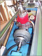

 Before that it had a 12 volt 17 amp battery which I used for starting a model boat engine. I think the Roper killed it.
 Also seen being turned is a reducing bush for the inside of the rose bearing.


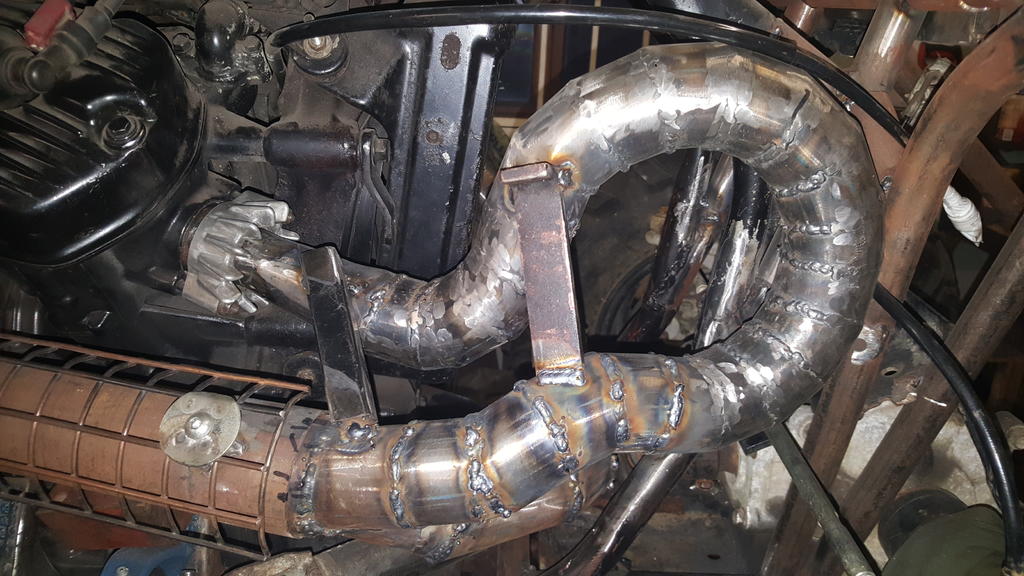
 , its not a crack, its the water level as its coming to the boil

 Is it that time of year AGAIN.
  Same as above. Happy Christmas to all.


Kubota 7100 1978 project
in Ride On's
Posted
100% better looking now Nigel. Did the welding cure the leaking cylinder head. ?