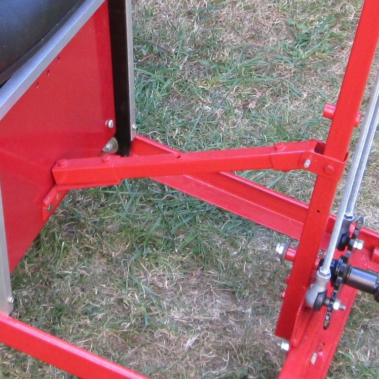
After discarding the chain drive the top sprocket was drilled and tapped 4 BA and an alloy bar bolted to it. This bar was drilled with extra holes for the push / pull rods so that various positions could be tried. The same was done with the bottom sprocket. The threaded rods are M6. These will be changed to round bar later and a better top bar made. All a temporary try out for now.
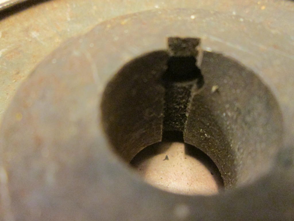
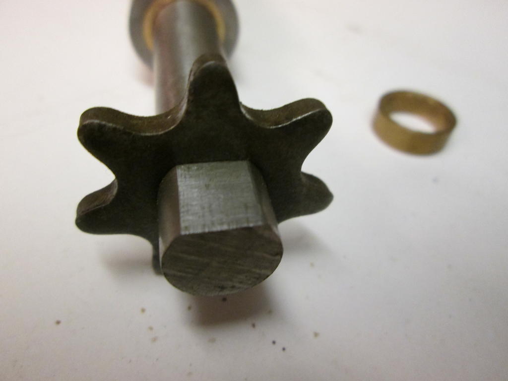
Although this arrangement was better than the chain, there was still a lot of free play. A lot of this was from the various universal joints and male / female connections between the bottom sprocket and the front wheels. Better fitting U/J centers were made and various Male F/M joints drilled and tapped for grub screws which tightened things up but still not enough. The gap between the pin and it's through hole can be seen below. The cavity for the small coil spring didn't help either as a lot of the bearing surface was lost. This was not used in the replacement centers. Probably cheap U/J's found at my usual parts supply location.
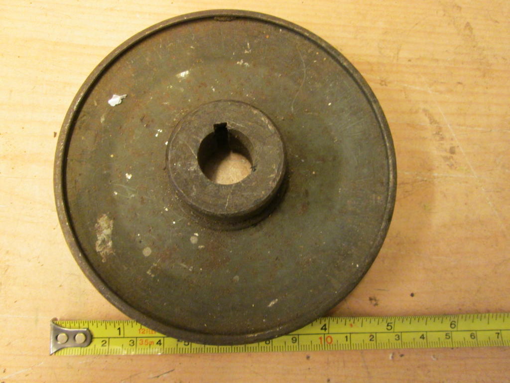
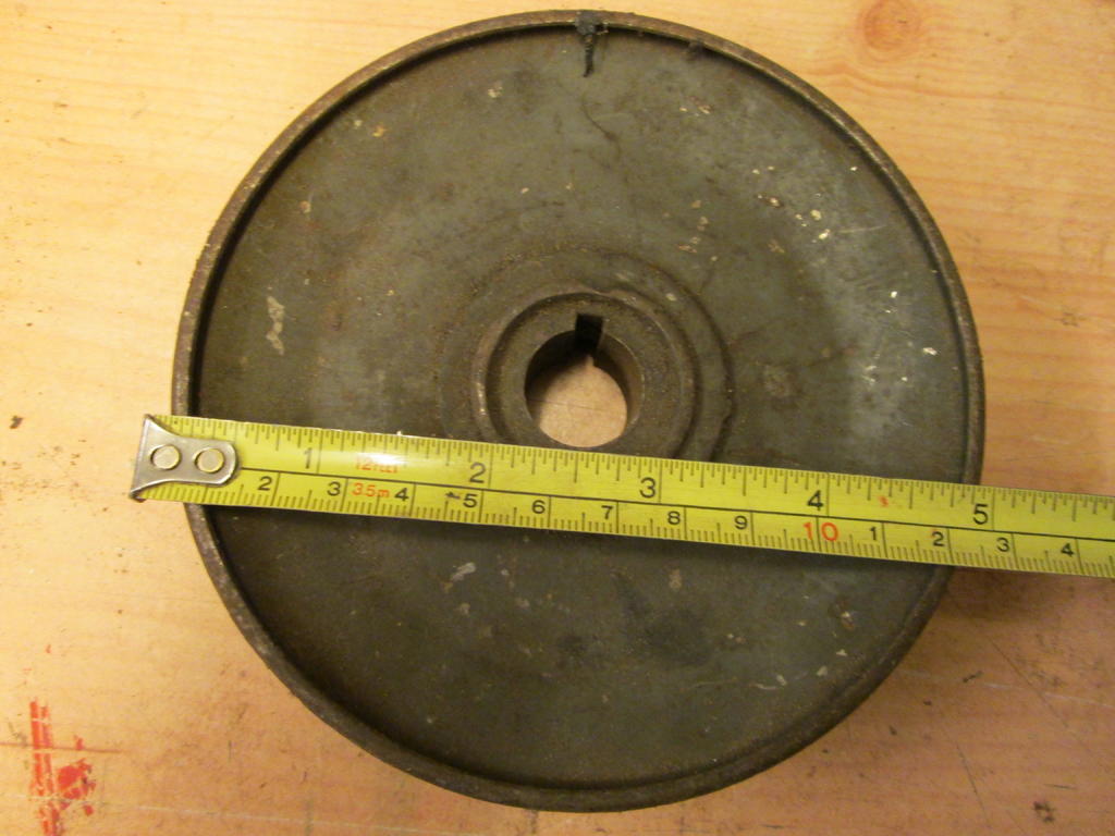
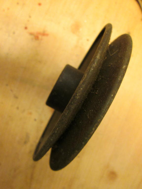
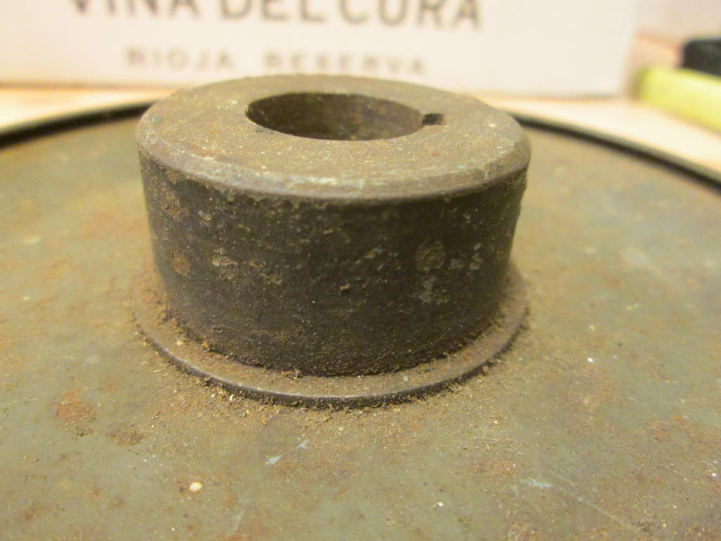
Found another pulley if any good. 5 inch with a 3/4 inch bore. 3/16" key way. Only 1/2" belt size though. Edit. Just seen your post. Looks like you might be sorted.
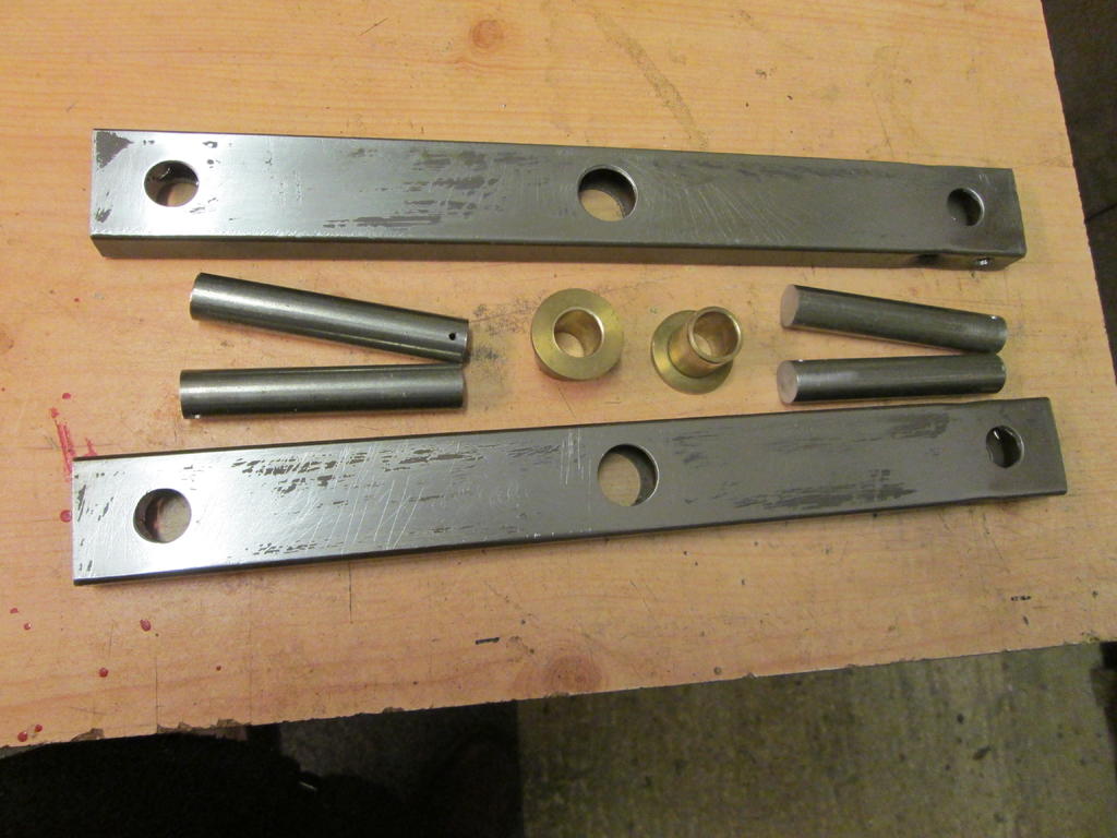
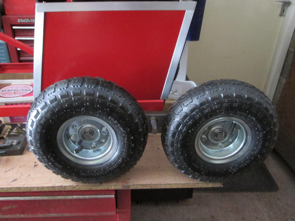
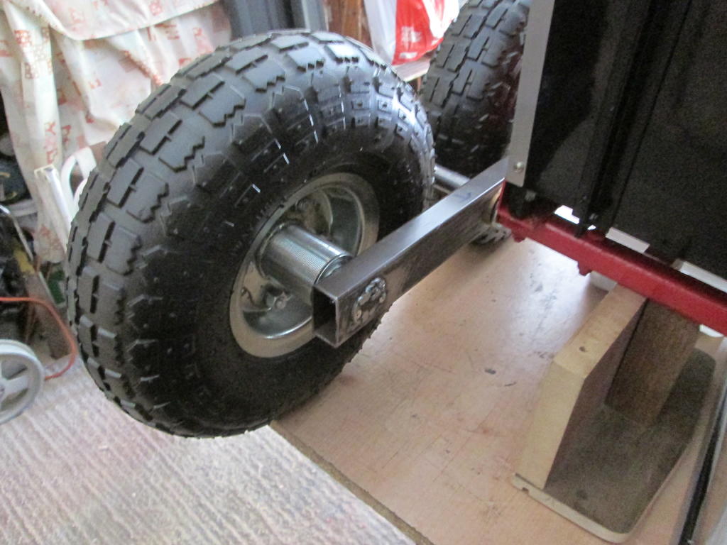
I did think of having four wheels on rocking beams but decided against it for now. I had bought four wheels extra cheap from eBay. The seller bumped the price up soon after, probably realizing his listing mistake. I made and tried the four wheel arrangement which could be easily changed over via quick release R clips. Could even have three wheels, two one side and one the other. The rocking beam parts before assembly and on the trailer.
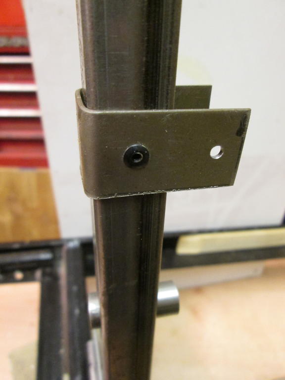
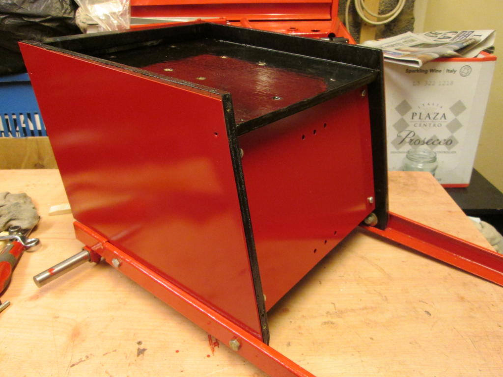
The steering column was made to hinge down for more compact storage but didn't save much space so just left in the upright position. The bracing strut can be fitted as shown, or in a horizontal position which I thought might make the assembly more rigid. Extra bolt holes were drilled in the face of the seat box. Again left as it is as no difference either way.
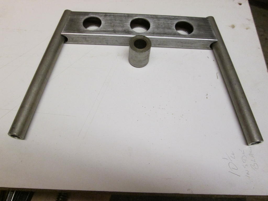
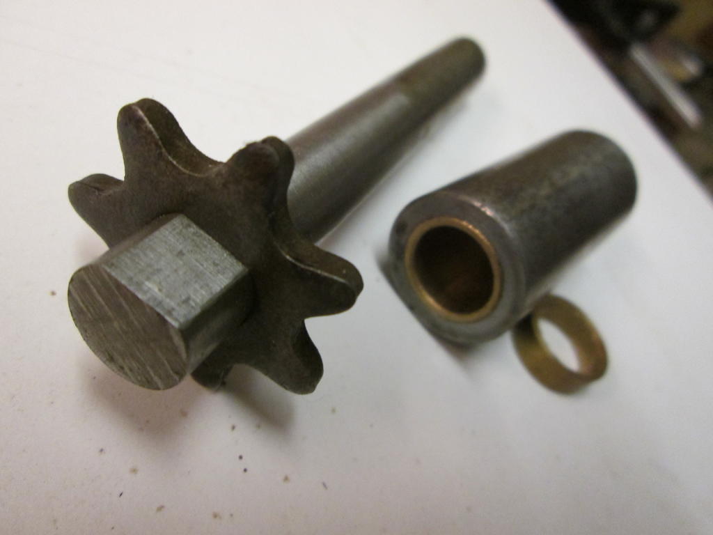
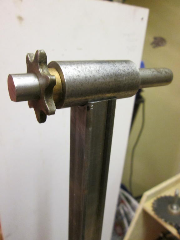
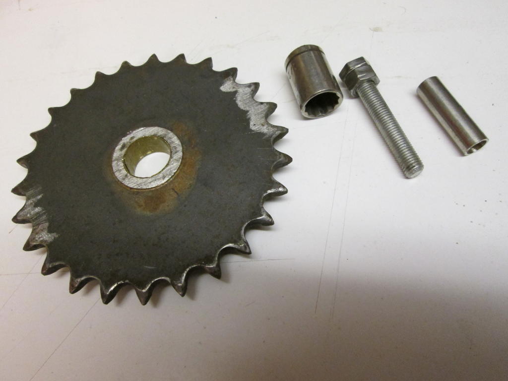
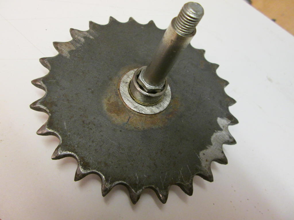
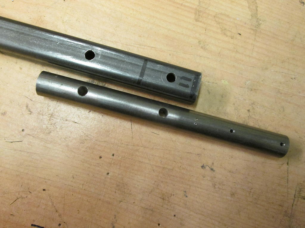
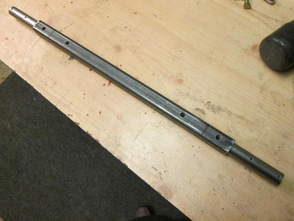
Some of the column and steering parts. I tried a chain and sprocket first, parts from a lawn mower which were heavy and had too much free movement. Later changed to push / pull rods. The top sprocket which had a D shaped hole was pressed onto it's 1/2" shaft after filing the shaft to fit. Was going to be welded but it hasn't moved yet. The yoke is a mixture of box section and tube shown before welding by the Showman, along with the following parts. Thanks Chris.
The bottom sprocket, a 3/8" drive socket, bolt and tube, were all welded together forming the pivot and drive between the trailer and tractor. A piece of shim was inserted to take up the gap around the socket.
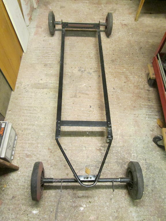
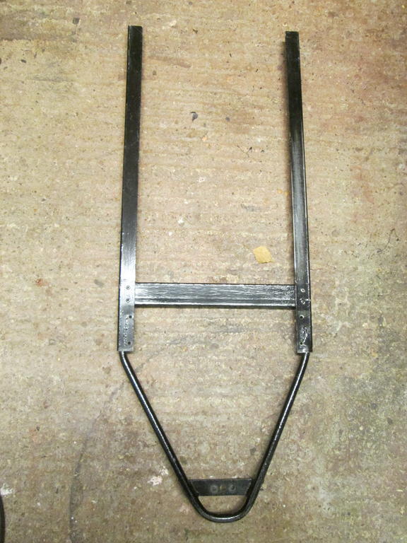
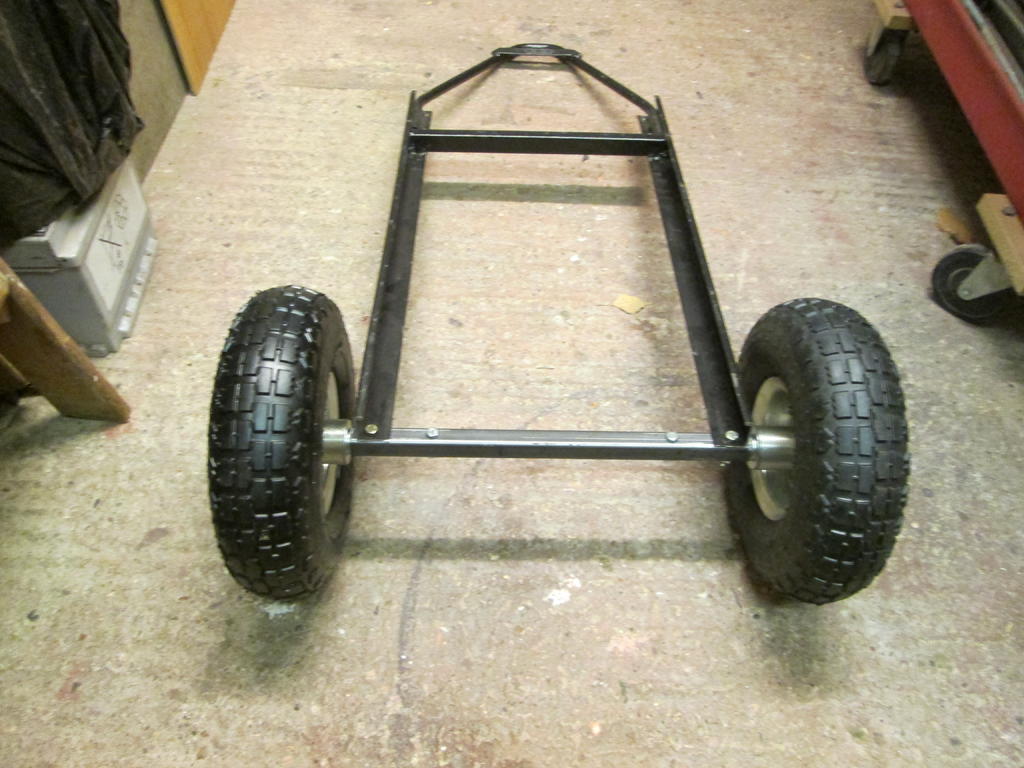
Still bits and pieces to do on the tractor but have also been working on the trailer. Wanted this to be as compact as possible but still big enough to sit in comfort. The chassis started life as a transport frame for motor cycles, shipped in part assembled form to a dealer near where I worked. This was altered to a trolley using wheely bin wheels with a storage box and frame on top so that I could move large model boats from the car to lakeside at the various locations we sailed at. Most lakes did not have access for cars, only footpaths. The trolley frame is shown below minus it's towing handle.
This now out of use frame was cut down and used for my sit on trailer. A new axle was made from box section and 16mm bar bolted together and to the frame, using pneumatic wheels instead of the solid tires used for the boat trolley.
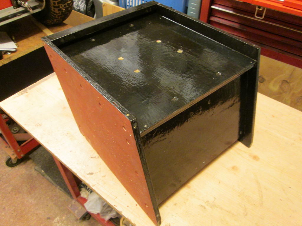
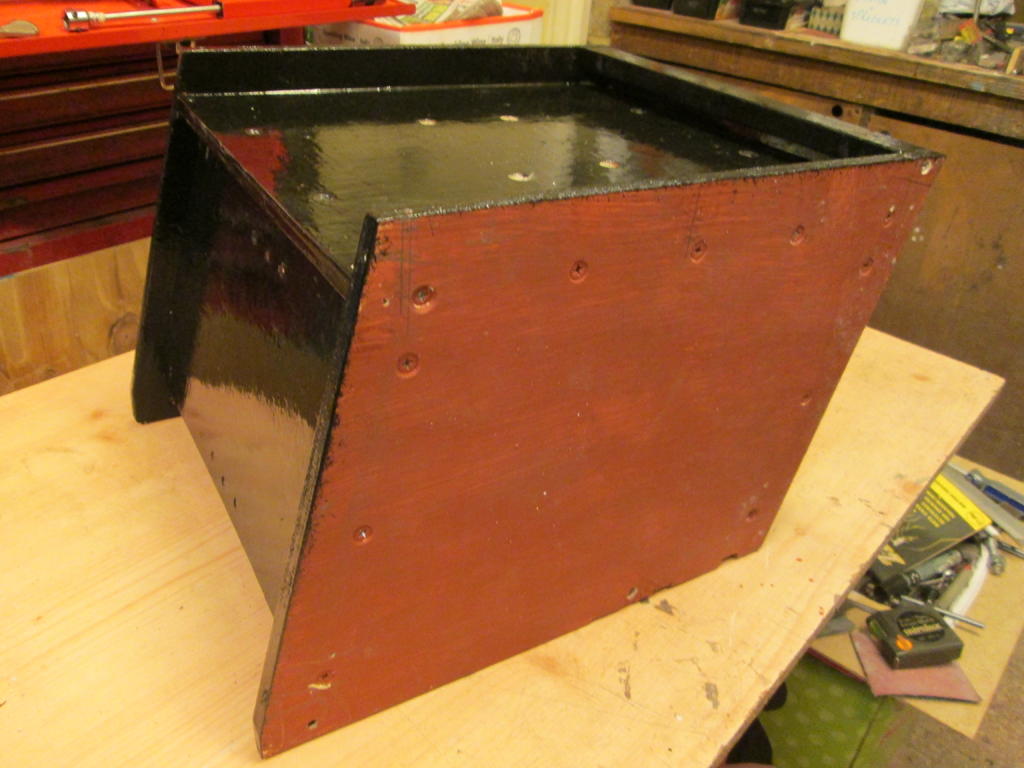
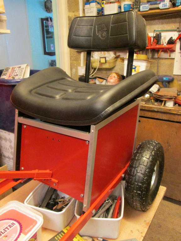
The seat mount was made up from scrap ply with alloy sheet outer panels. The edges were trimmed with alloy angle, more scrap salvaged when clearing my friends land.
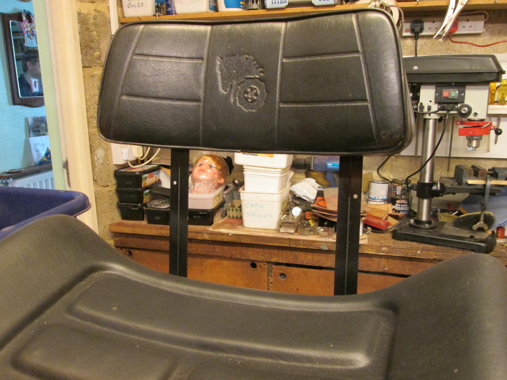
The sit on part of the seat is actually the backrest part of a seat I bought on eBay. The seat section looked too big when fitted so went into storage. Short lengths of studding were fitted into the already welded in mounting nuts and just drop into holes in the box top. Hope this makes sense.
The now proper backrest, complete with it's Wheel Horse motif, was kindly donated by Chris the Showman, and is mounted on doubled up lengths of alloy angle.


") Happy Birthday Paul.
Happy Birthday Paul. 

 The rocking beam parts before assembly and on the trailer.


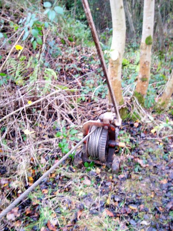
 Camera doesn't always behave. A bit like me.
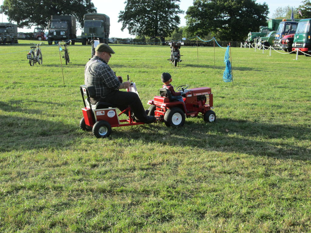
HALF a HORSE.
in Home Built Items
Posted
After discarding the chain drive the top sprocket was drilled and tapped 4 BA and an alloy bar bolted to it. This bar was drilled with extra holes for the push / pull rods so that various positions could be tried. The same was done with the bottom sprocket. The threaded rods are M6. These will be changed to round bar later and a better top bar made. All a temporary try out for now.
Although this arrangement was better than the chain, there was still a lot of free play. A lot of this was from the various universal joints and male / female connections between the bottom sprocket and the front wheels. Better fitting U/J centers were made and various Male F/M joints drilled and tapped for grub screws which tightened things up but still not enough. The gap between the pin and it's through hole can be seen below. The cavity for the small coil spring didn't help either as a lot of the bearing surface was lost. This was not used in the replacement centers. Probably cheap U/J's found at my usual parts supply location.