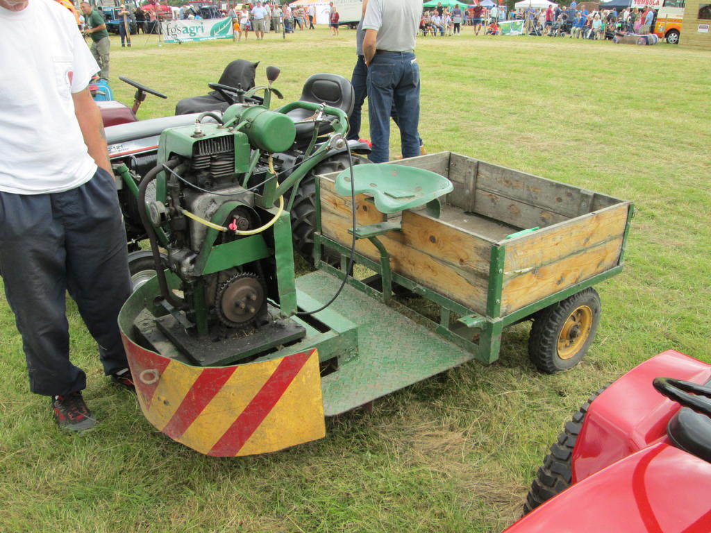
There was a Lawnbug at John's place. Sold it on eBay for £100 long before the big clear out started. Not sure what model but remember it was green with a white engine. Non runner and scruffy condition.
I think the next part I attempted was the dash assembly. Two 3/16" thick alloy panels were cut for the front and rear with a bent up alloy spacer pop riveted on. When first looking at photo's I had thought that both front and rear had an apex on the top surface. It was only after I had build number one well on the way that my man with the camera, tape and notebook, Iain, pointed out my mistake. I made three or four alterations, gradually reducing the front apex and leveling off the rear before it looked about right. These photo's are before any alterations.
The outer shell was originally bent so that it finished on the underside and left oversize back and front for trimming later. The first attempt also looked too long when viewed from the side.
This photo shows the top rear looking more like it should be.
There were a lot of alterations and head scratching before the final result which included brackets bent up to hold front, rear and outer shell together. Also a strong mount for the steering column bush and cross beams for mounting to the upper side panels. Lots of assorted BA nuts and bolts were used which resulted in a very strong assembly.
The brackets set at an angle on the front face are for the spring loaded hood locking catches, more of these later. The Steering column bush is a 1/2" socket cap screw drilled 5/16". I drilled two of these, the second for the steering wheel. This will also be described later.
After the grill and surround was mounted it was thought that additional support would be a good idea. Various ways were thought up and discarded. Some being too unsightly, others not rigid enough. The method finally settled on was simple and strong. Two brackets were bent up which were bolted to the front face of the engine cover and to the underside of the grill surround. 4BA nuts and bolts were used making sure that the holes drilled in the cover were clear of the fuel tank underside and internal deflectors. These photo's are out of focus but show the set up.
The headlamp surround was bent up around a shaped wood former. I don't appear to have photo's of this. The full size was welded to the grill surround but bolted on the model, again using 4BA nuts and bolts. These can just be seen on the grill photo above.
Just found the photo's that I couldn't find. This shows the cross member assembly trial fitted at the front of the chassis. Thought I also had one showing it before fitting but no sign of it.
Should have mentioned earlier that I had a LOT of help from Iain ( slf-uk ) with photo's and measurements. On one of his numerous visits to John's he mentioned that he had a D-160 and 200 and offered to obtain any details I required. This offer was taken up countless times with Iain dropping everything, day and night, and rushing into his workshop with camera, tape, and notebook. Well, not quite rushing but a speedy response. A lot of the photo's found on the internet didn't show details from the correct angle but a request to Iain explaining what I wanted produced the required result. A BIG THANKS Iain.
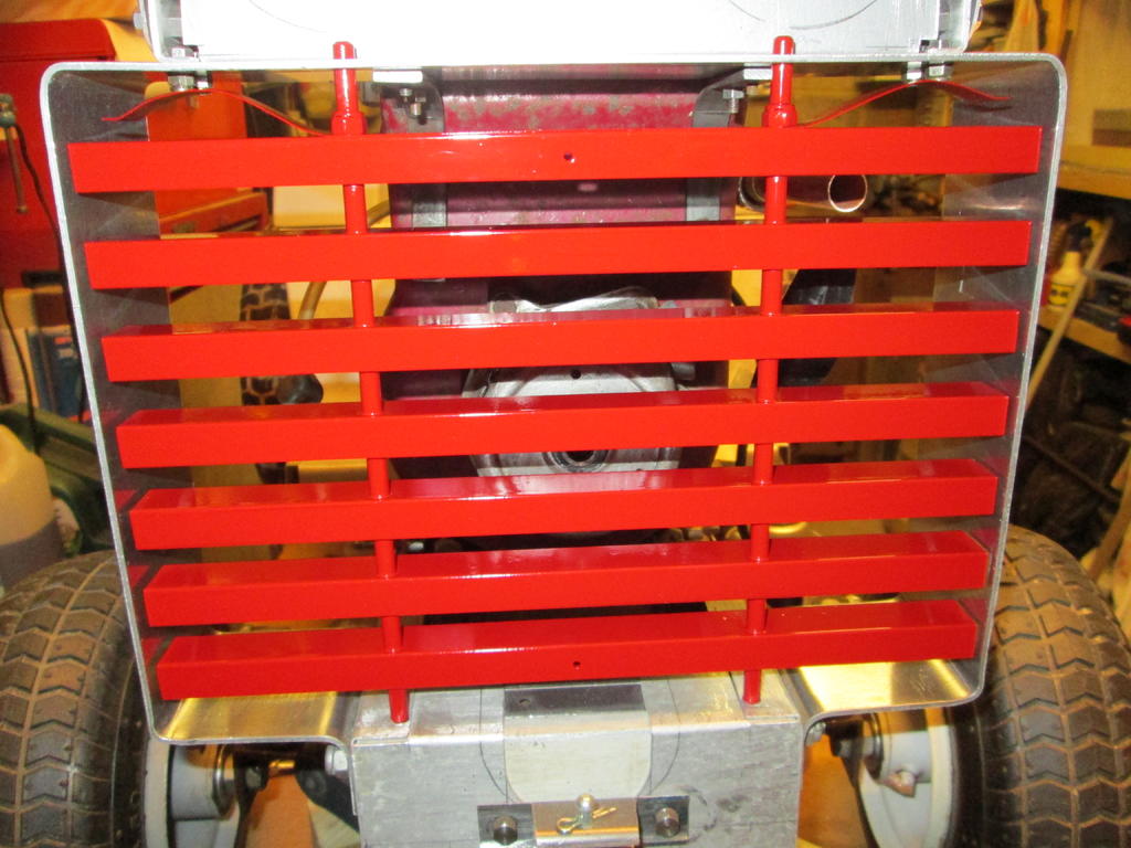
Now that the grill surround was made it needed something to fill the hole. The grill was made from 3/4 x 1/2" alloy angle with 3/16" silver steel uprights, threaded 2BA at the top and drilled 1/16" at the bottom for a wire pin. The spacers were from alloy tube. Using the 1/2" width of the angle as the front face with a 1/2" gap between each plus the same top and bottom looked about right. A lot of careful measuring, cutting and drilling gave a good copy of the original. The anti rattle leaf spring at the top was from steel shim with threaded tubes over the tops of the uprights where they protruded through the grill surround. This alloy angle was from a green house which John and I dismantled years ago for a friend of his, transported back to his land, stored behind his shed and has never moved until recently. I saved a good selection of various sizes.
Finally, I just had to give the grill a coat or two of paint, the first item painted, to see what it looked like.
One of the few pieces of metal which was not found as scrap was the grill and headlamp surround. Nothing of suitable thickness to hand but the Showman came to the rescue and obtained some cut to width alloy from a contact of his. Thanks Chris. A jig was made up from a thick sheet of board and coach bolts. Allowance was made when fitting these bolts for the thickness of the metal, either side and top and bottom, so that the correct outside width and height was obtained. The alloy strip was clamped to the bolts and bent around in stages. Two of the lower bolts not yet fitted in the photo's.
The front chassis cross member was made up from various metal and alloy pieces all bolted together and in turn to the chassis. As the front mounting bolts of the grill passed into a box section with no way of fitting nuts, a length of 1/4" stud was used instead which passed through the total width of the chassis leaving enough either side for nuts and washers. Cannot find photo's of this assembly at this stage.
Thanks Chris. As can be seen, I couldn't get my leg over, I mean over the tiller steering lever. Under it didn't work either so had to let it dangle while leaning to the left to keep balanced. Not very comfortable. I think this is when it was decided that operating from a trailer would be the best option.
Most impressed Alan. A little bench top Brake Press is a nice piece of gear to have (insert green envy emoticon).
Thanks Richard. Chris found it and it went down to the coast in his mobile shed. He let me borrow it back though. We think it came from a deceased friend of John's who restored vintage cars.
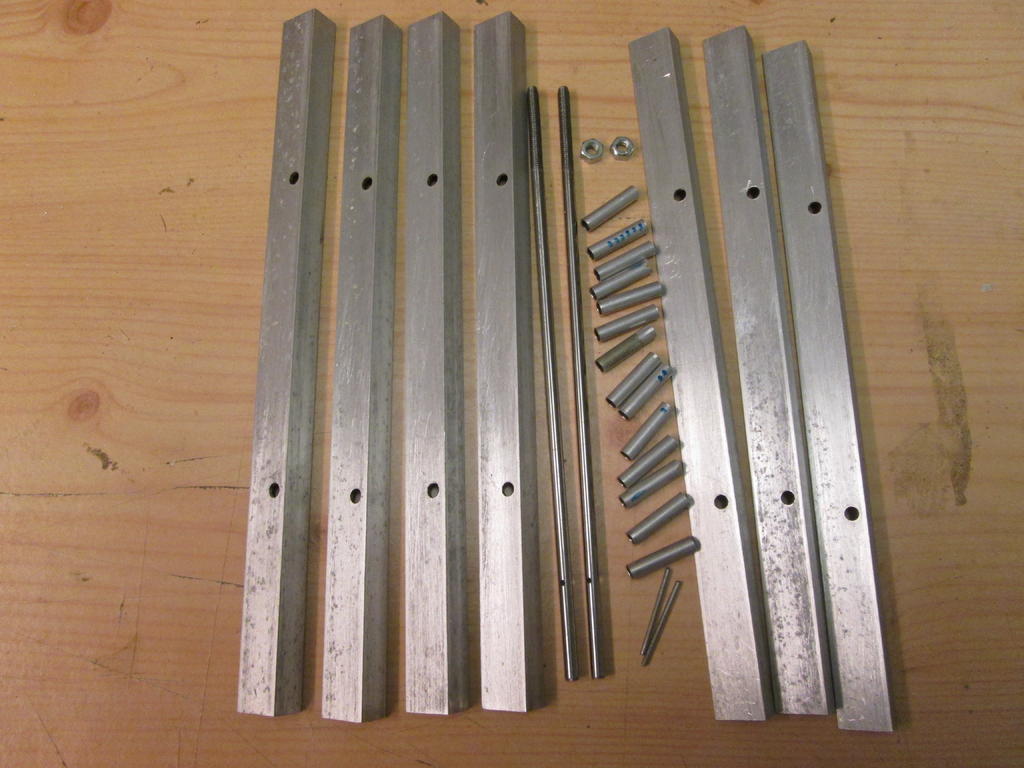
As the Showman has not yet put the other video's on utube, ( he must be extra busy hiding firewood from Pam ) the next stage was to make up the side panels. First were the chassis extensions. These were made 5/8" deeper than the chassis box section, to give scale depth, with an extra 1/2" added top and bottom for folding over.
The bottom fold was to give extra strength and also to help stop the skin of my hands from being attacked by what would have been a sharp edge while constantly reaching under during the build.
This can be seen on the photo's. A right angle bend followed by tapping over then finished by flattening in the brake press.
This brake press, with a capacity of about 24" was found by the Showman during the clear out at friend John's place. He also finds things which are not RED. Old but effective especially with the 1mm approx alloy sheet used for the panels. These panels were, we think, either from old buses or maintenance vehicles. John had a friend who worked for a local bus company. These were large panels with the remains of paint and lettering, some with cut outs which could have been vents. Whatever they were they were recycled and put to good use.
The chassis side extensions were followed by the wider upper panels, two long next with the shorter top two having a slightly angled rear edge. These top two, marked out and bent up as a pair, overlap the lower ones like the full size and are folded over at the rear. All shown just loosely fitted along with the upper rear panel.
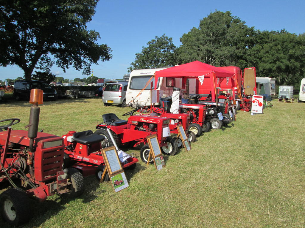
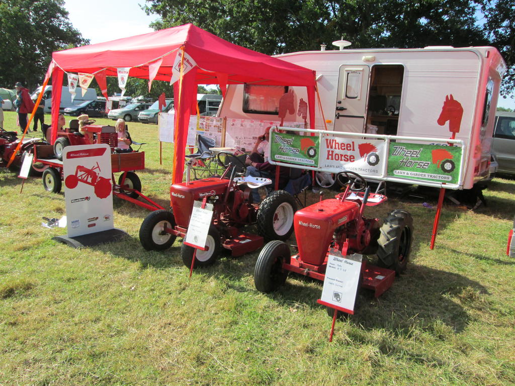
A GREAT show Kev. One of the best I have attended. My first visit and I hope to be there next year too. Lots of variety and plenty to see. Thanks to you and your team for all your hard work.
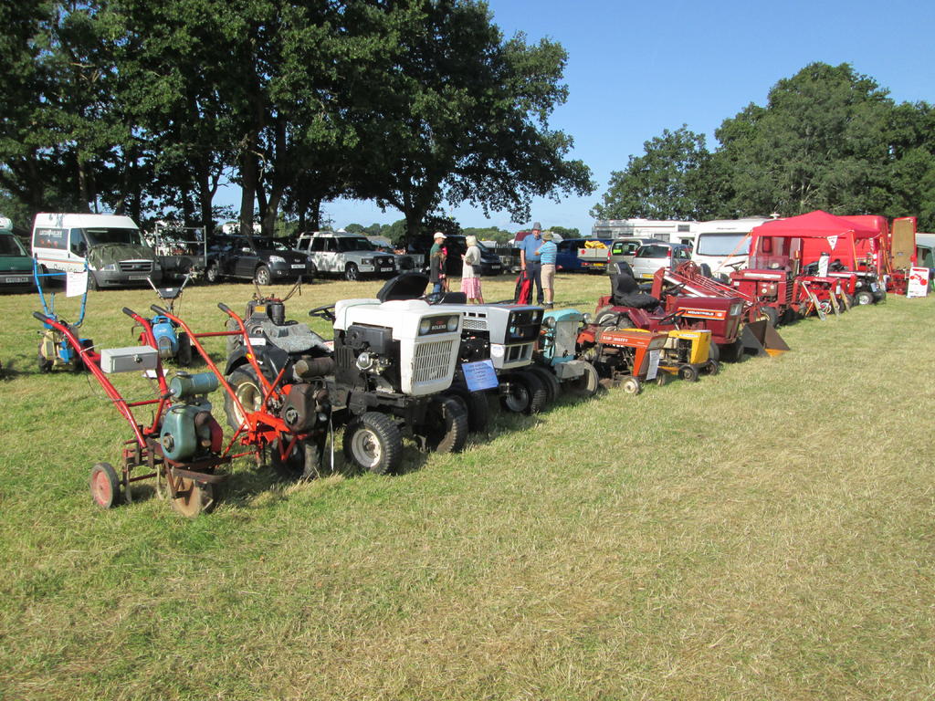
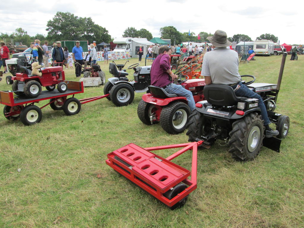
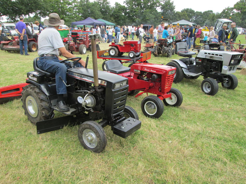
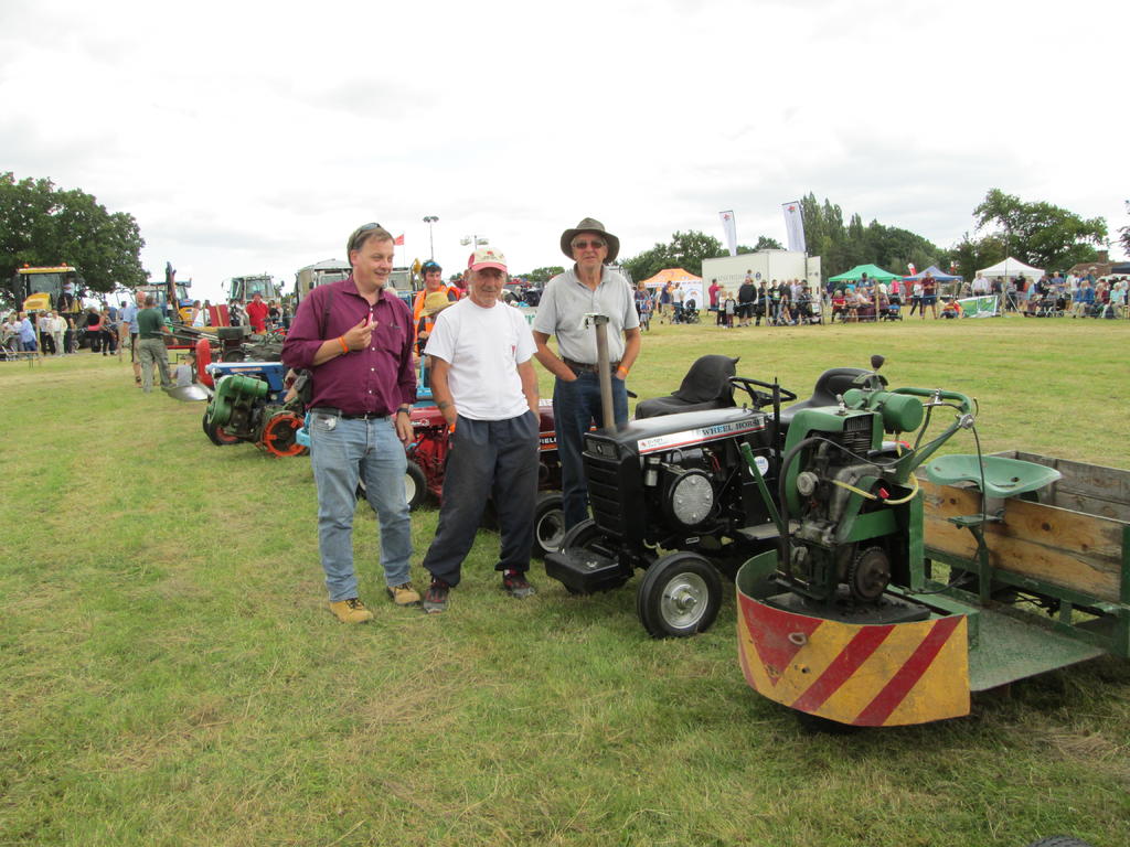
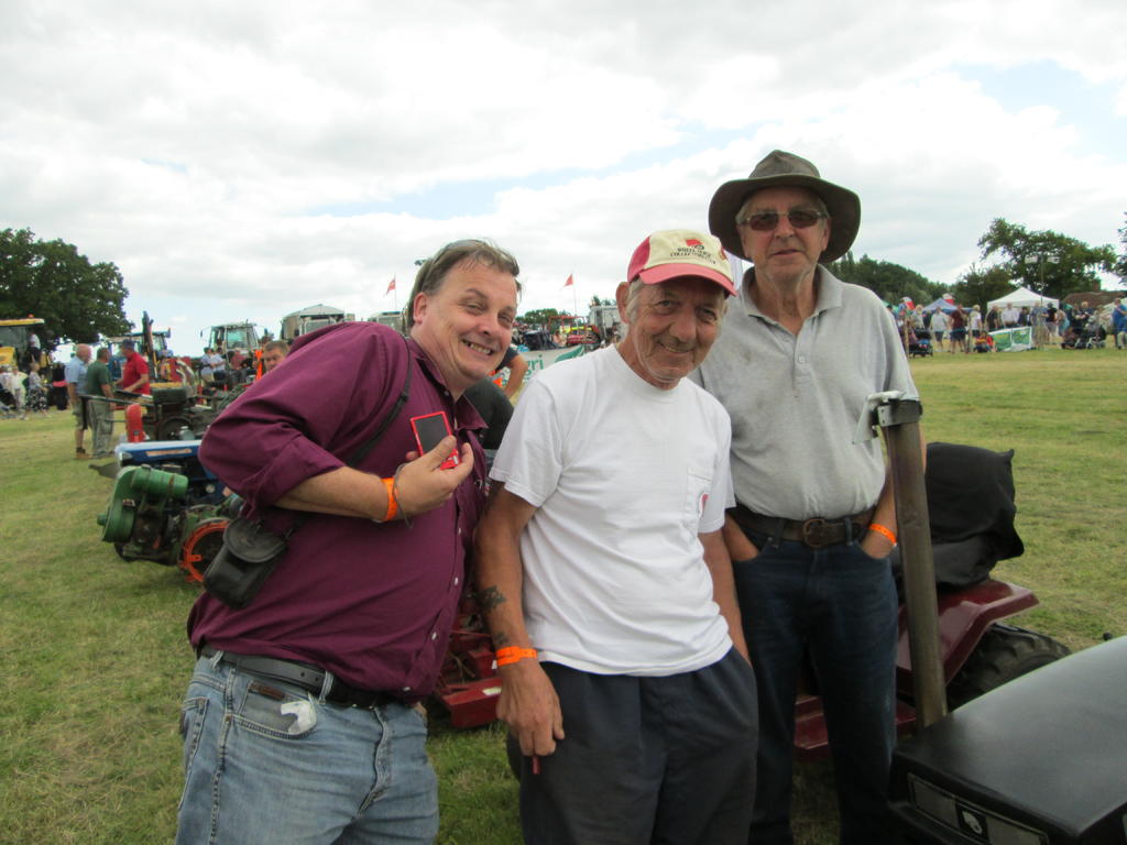
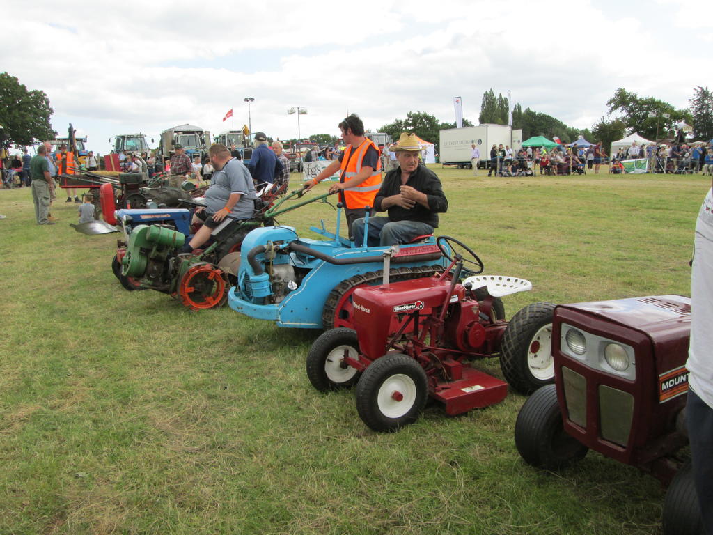
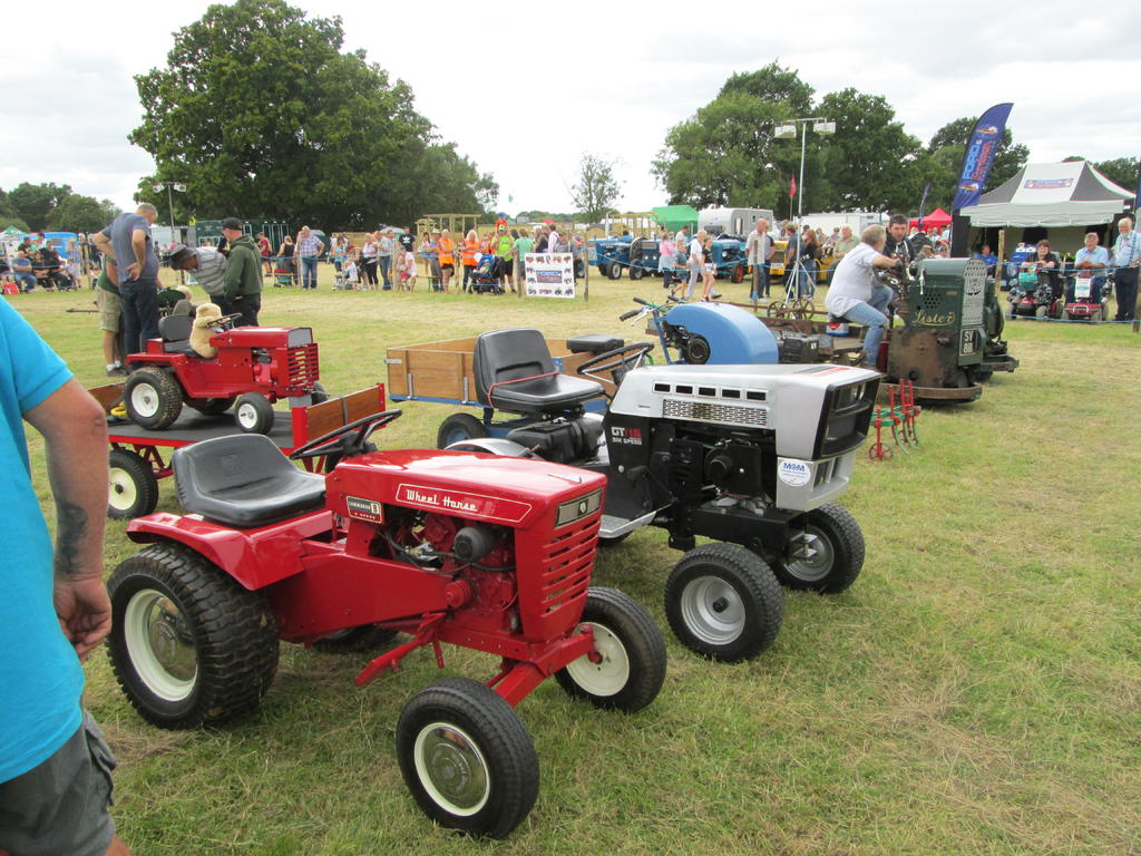
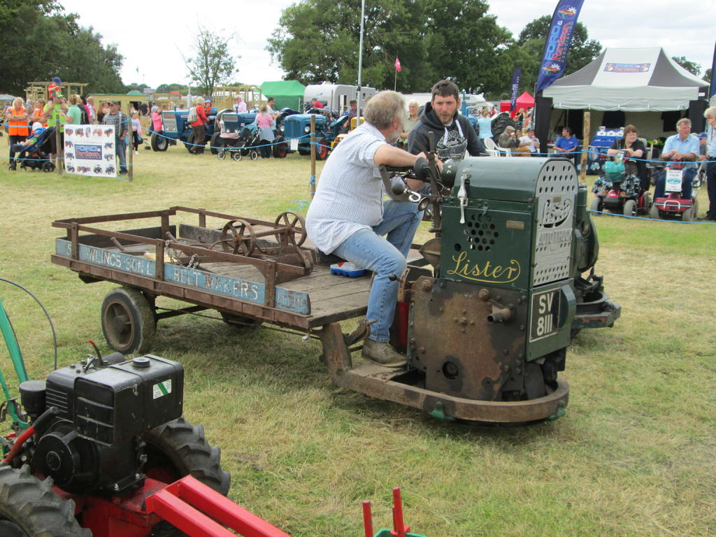
Thanks Chris for all your work, the tea, coffee, banter etc. I expect there will be more comments about my suspenders from a certain American friend. A few more photo's of mine.
Pam said she wanted more twigs for her wood store, so Chris was wondering how to get this lot home.


")


 As if you didn't know.


 Looks too good to use.


 I mean over the tiller steering lever. Under it didn't work either so had to let it dangle while leaning to the left to keep balanced. Not very comfortable. I think this is when it was decided that operating from a trailer would be the best option.
 Most impressed Alan. A little bench top Brake Press is a nice piece of gear to have (insert green envy emoticon).
 We think it came from a deceased friend of John's who restored vintage cars.
 ( he must be extra busy hiding firewood from Pam ) the next stage was to make up the side panels. First were the chassis extensions. These were made 5/8" deeper than the chassis box section, to give scale depth, with an extra 1/2" added top and bottom for folding over.


 You have been listening to a certain R/S member too much.

Happy birthday DougC
in Off-Topic Discussion
Posted
Happy Birthday Doug.") Hope all your 64 burning
Hope all your 64 burning 
candlestelegraph poles fit on your cake.