Leaderboard

Popular Content
Showing content with the highest reputation on 12/16/2018 in all areas
-
2 points

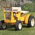
Slumbering Westwood
WestwoodW8Gazelle and one other reacted to mattblack for a post in a topic
This lives at work, it hasn't moved in the 9 1/2 years that I've been there. I'm not sure if the deck is still around or went in a scrap clearout. -
2 points
HALF a HORSE.
Cub Cadet and one other reacted to Alan for a post in a topic
Another update. The telescopic steering shaft was made from square box section tube, welded to the U/J which in turn plugged into the lower sprocket on the trailer. The inner sliding part was a length of 1/2" square bar filed to a nice sliding fit. This was drilled and threaded then screwed tightly onto the round rod which formed the other half of the shaft. A pin through the square bar and rod made sure nothing moved. A short extra piece was added later to give a bit more bearing surface although probably not needed. A bit of surface rust showing since it's last use. The large threaded hole is a left over from it's last life. The second photo shows it in it's storage position, held in place with the throttle cable. The trailer is disconnected by removing the throttle lever from the steering yoke, one screw, pulling the coupling pin and moving the trailer back which slides the two shaft sections apart. Coupling all together is just as simple. The throttle cable had to be extended to approx twice it's length. Think it was originally fitted to a lawn mower. Couldn't find anything suitable on the internet. The inner was 1mm. Most others found were 1.25 or 1.5mm. I could have opened up the cable slot in the carb piston but decided against this as after a bit of hunting found 1mm inner cable was available from China. A 5 metre length for £1 25 including postage. A 2 metre length of outer sleeve was found in the UK but couldn't find this to match the inner in China. Strange. After careful measurement the inner was cut to length and a short piece of brass tube soldered on one end. The carb top, outer sleeve etc was assembled followed by the lever end nipple being soldered in place. After connecting to the trailer everything was found to operate smoothly and with approx the same amount of movement as the original cable. This photo shows the new inner and brass tube nipple alongside the old. -
1 pointThought I would share my latest edition. Picked up this Strikemaster Icemaster today. Runs ok but need a thorough cleaning and tune up.
-
1 pointTake George up on his offer, Alain. He gave me a lot of good advice.
-
1 point
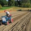
Weekend ploughing
HeadExam reacted to The Fife Plooman for a post in a topic
Hi can you put up some pictures of your setup may be able to guide you , keep well -
1 pointAwesome job! looks mint
-
1 point
HALF a HORSE.
pmackellow reacted to Alan for a post in a topic
After discarding the chain drive the top sprocket was drilled and tapped 4 BA and an alloy bar bolted to it. This bar was drilled with extra holes for the push / pull rods so that various positions could be tried. The same was done with the bottom sprocket. The threaded rods are M6. These will be changed to round bar later and a better top bar made. All a temporary try out for now. Although this arrangement was better than the chain, there was still a lot of free play. A lot of this was from the various universal joints and male / female connections between the bottom sprocket and the front wheels. Better fitting U/J centers were made and various Male F/M joints drilled and tapped for grub screws which tightened things up but still not enough. The gap between the pin and it's through hole can be seen below. The cavity for the small coil spring didn't help either as a lot of the bearing surface was lost. This was not used in the replacement centers. Probably cheap U/J's found at my usual parts supply location. -
1 point
HALF a HORSE.
pmackellow reacted to Alan for a post in a topic
I did think of having four wheels on rocking beams but decided against it for now. I had bought four wheels extra cheap from eBay. The seller bumped the price up soon after, probably realizing his listing mistake. I made and tried the four wheel arrangement which could be easily changed over via quick release R clips. Could even have three wheels, two one side and one the other. The rocking beam parts before assembly and on the trailer. The steering column was made to hinge down for more compact storage but didn't save much space so just left in the upright position. The bracing strut can be fitted as shown, or in a horizontal position which I thought might make the assembly more rigid. Extra bolt holes were drilled in the face of the seat box. Again left as it is as no difference either way. Some of the column and steering parts. I tried a chain and sprocket first, parts from a lawn mower which were heavy and had too much free movement. Later changed to push / pull rods. The top sprocket which had a D shaped hole was pressed onto it's 1/2" shaft after filing the shaft to fit. Was going to be welded but it hasn't moved yet. The yoke is a mixture of box section and tube shown before welding by the Showman, along with the following parts. Thanks Chris. The bottom sprocket, a 3/8" drive socket, bolt and tube, were all welded together forming the pivot and drive between the trailer and tractor. A piece of shim was inserted to take up the gap around the socket. -
1 point
HALF a HORSE.
pmackellow reacted to Alan for a post in a topic
Still bits and pieces to do on the tractor but have also been working on the trailer. Wanted this to be as compact as possible but still big enough to sit in comfort. The chassis started life as a transport frame for motor cycles, shipped in part assembled form to a dealer near where I worked. This was altered to a trolley using wheely bin wheels with a storage box and frame on top so that I could move large model boats from the car to lakeside at the various locations we sailed at. Most lakes did not have access for cars, only footpaths. The trolley frame is shown below minus it's towing handle. This now out of use frame was cut down and used for my sit on trailer. A new axle was made from box section and 16mm bar bolted together and to the frame, using pneumatic wheels instead of the solid tires used for the boat trolley. The seat mount was made up from scrap ply with alloy sheet outer panels. The edges were trimmed with alloy angle, more scrap salvaged when clearing my friends land. The sit on part of the seat is actually the backrest part of a seat I bought on eBay. The seat section looked too big when fitted so went into storage. Short lengths of studding were fitted into the already welded in mounting nuts and just drop into holes in the box top. Hope this makes sense. The now proper backrest, complete with it's Wheel Horse motif, was kindly donated by Chris the Showman, and is mounted on doubled up lengths of alloy angle. -
1 point
HALF a HORSE.
pmackellow reacted to Alan for a post in a topic
Another little update after another delay. Too many things to do. Who said retired people have plenty of spare time. The hood catches which started off as 3/16" diameter car brake pad pins. An alloy sleeve pressed on, drilled 1/16" for a short piece of wire, then the domed head turned off. 1/2" ID alloy box section was pop rivited to the inside of the hood after drilling for the pins. A nut and bolt held it in place while drilling for the rivits. Another 1/16" hole was drilled for the retaining R clip after careful measurement to make sure it was in the correct place. It was. More measurement and head scratching then the excess was cut from the pins and the ends chamfered. When closing the hood the pins slide down slightly angled plates before popping into holes near the base. These plates can be seen on this earlier photo of the dash panel. The pins are sprung into place by springs, what else, taken from AA size battery boxes. These were inserted into the alloy box first, then compressed with special tool which I carefully designed then made, allowing room for the pin to pass through. OK, a piece of scrap alloy with a slot filed in it did the job. It was a pig of a job to hold the compressed spring, hold the pin steady, and insert the R clip, while trying avoid it pinging off into the distance. If the R clip had been long enough to protude outside the alloy box it would have been easier. The clip can be seen to the left, the rivits to the right. A washer between the clip and spring would have been better but I gave up trying to fit one. Kept going awol. The parts almost ready to be fitted. Works as intended although just as easy to pull the bottom corners of the hood out slightly which releases the pins. -
1 point
HALF a HORSE.
pmackellow reacted to Alan for a post in a topic
Turning brakes. I was undecided on these. Should I fit them, or not. OK, I'll make a start. Bent up a pair from alloy using photo's and guesswork as a size guide. The levers ? were from 1/8" x 1/4" brass drilled and tapped 8BA. Each lever was made in two parts as attempts to bend as per the full size resulted in a break. Brass too hard. Should have tried heating up first. These levers are probably a bit narrow, 3/8" would have been better but nothing in stock. It was then decided to leave them for now and carry on with other bits and pieces. Lots of bits and pieces later, Iain slf-uk my head information provider, sent me photo's and measurements of the assembly so a restart was made. My original guesstimated alloy pedals were correct in height and the inside of the bent up lips, much to my surprise, but 1/4" short in length. This 1/4" is the model size measurement. Two new pedals were made and the horizontal brass section extended using a piece of plastic for quickness. A test assembly. All these parts were held together with 8BA countersunk bolts. Looks a bit messy on the photo's but all hidden later. A few holes were drilled in the wrong place, but not seen when finished. The pivot bar is brass tube with a plastic insert and a 3mm threaded rod. All bits which just happened to fit together without much work. The lower ends of the uprights were drilled and tapped to suit the rod and the tube notched to take the inner upright. Easier than making the tube in sections as per the full size, and as these pedals won't be working, a bit stronger. The locking bar was also fixed in position. The notch in the tube was later filled and blended in. Various other areas had the same treatment to tidy things up. The brake pull rods! were from alloy angle , bolted to the underside of the footrest for extra strength with the nearly visible end trimmed down. I had to alter my original footrest support and lay it flat with the alloy angles notched to clear, but as usual after doing all this a better and simpler solution popped up in my head, but leaving as it is. Photo below is before cutting notches for support clearance. The full size has a steel bar running diagonally under the footrest, from the outer end of the pivot tube to the chassis frame, which helps support the tube. I made up a short alloy bracket which is bolted to the support angle in front of the pedals, and to the front underside of the footrest. Not really visible without effort. Hope all this makes sense. Grip tape was added to the pedals which finished them off as well as hiding all the bolt heads. The footrests also had a covering of the same. This self adhesive tape was listed on eBay as carpet gripper tape. Similar stuff also used for skate boards. I wanted to use ribbed rubber but nothing suitable found. All too thick. The next photo's show various stages of test fits. I could have left the cranked ends straight on the brake rods ! by moving them closer together, but had previously drilled the footrest and didn't want to waste the holes. Photo below. The pins connecting the rods to the uprights were made from a bolt, turned down and drilled, then cut to length. The split pins are 1mm diameter. The threaded end was screwed into the alloy rods after tapping and held with a dab of lock tight. A fiddly job inserting the split pins, especially the inner one resulting in chipped paint, now touched up. Might have been easier before fitting to the tractor. Not too happy with the appearance of these split pins. Need tidying up and the loop made smaller. A job for another time. A few more photo's of the various parts, mounting brackets, footrest support etc plus the unit finally fitted.