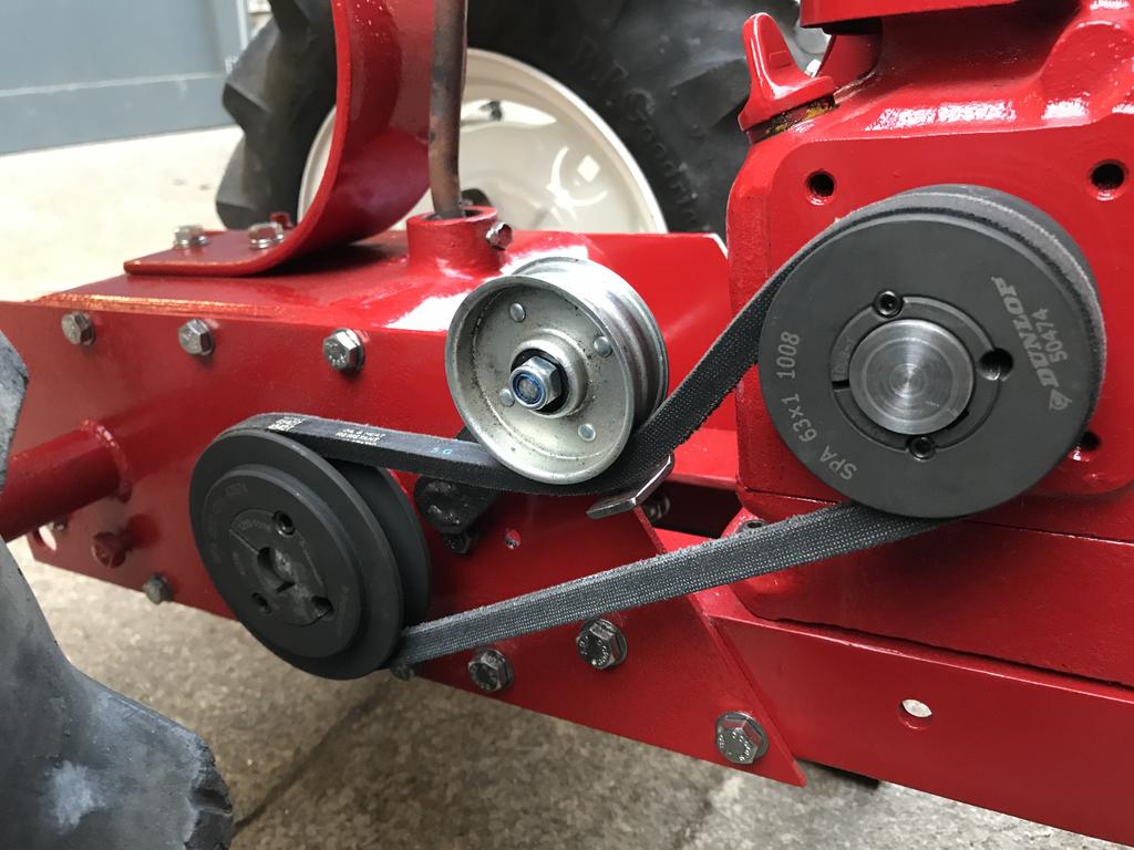
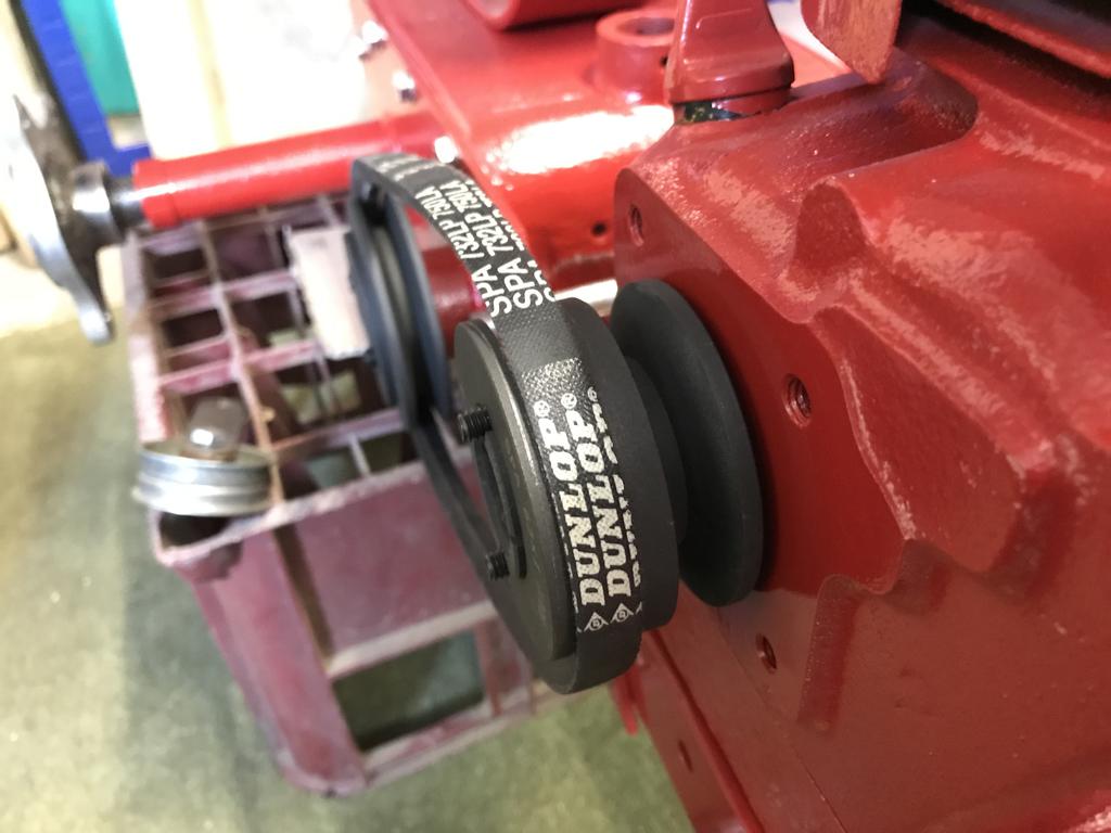
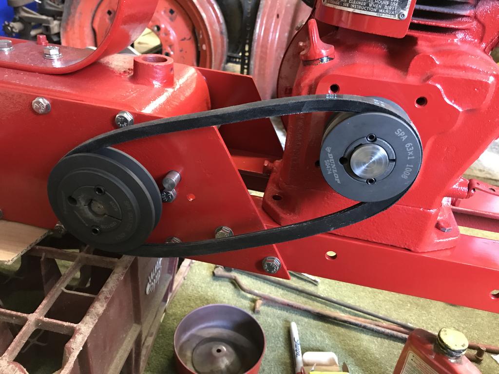
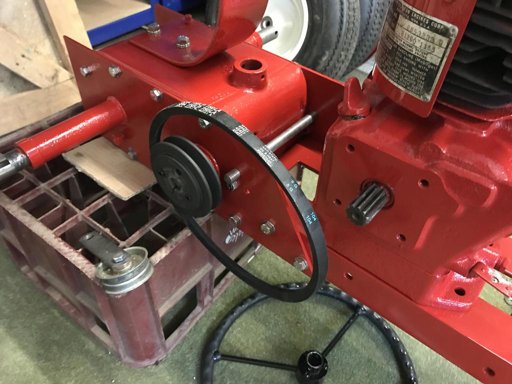
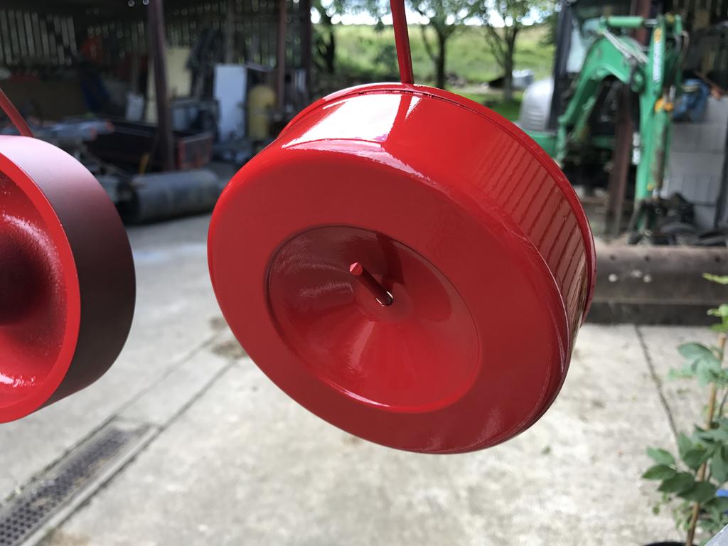
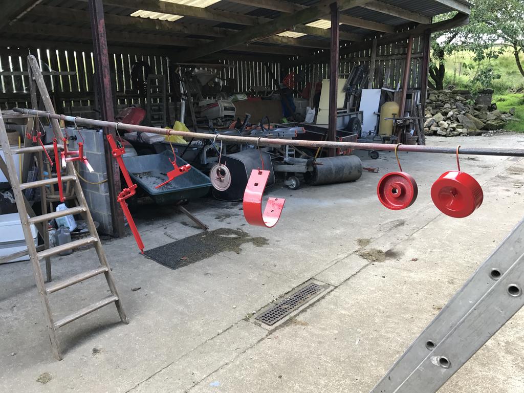
Just been out in the shed to look at mine, you've got the belt right , ive had them play up if the cover's not on. the cover stops the belt sagging at bottom and as Norm said the pulleys need to be shiney
Thanks Chris, I did read that the cover helped with the belt, thats next on the list of parts to make I think I may take the pulleys off and give them a polish next.
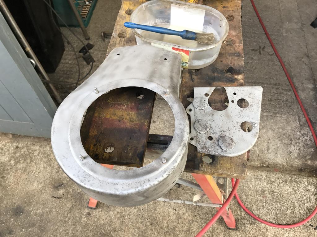
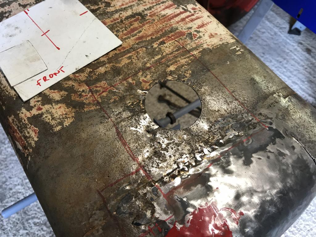
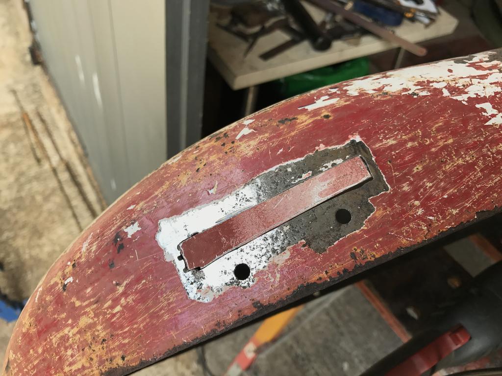
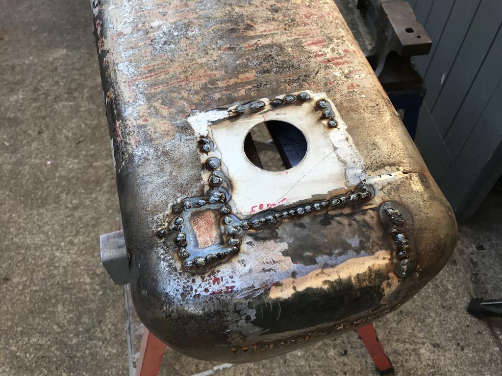
More replacement of the rusty metal and holes were next on the list.
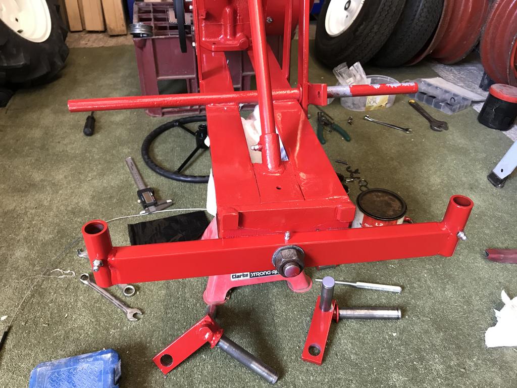
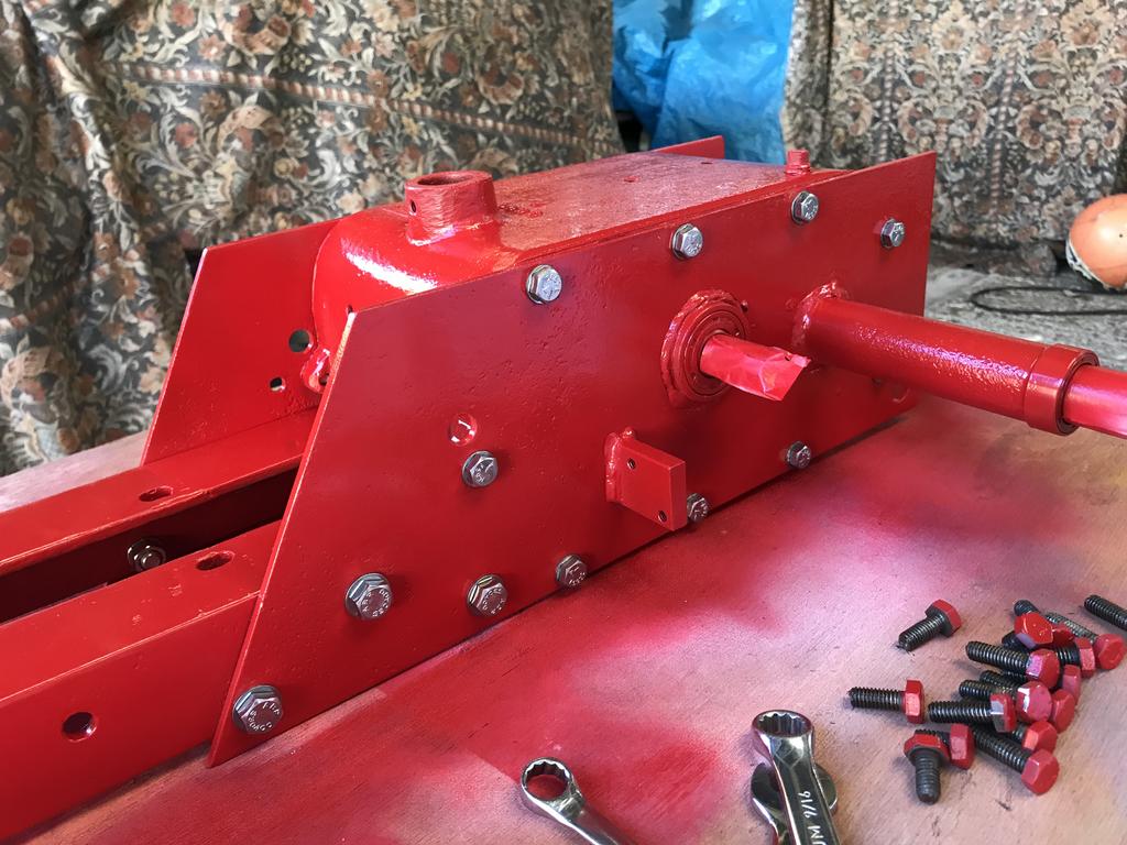
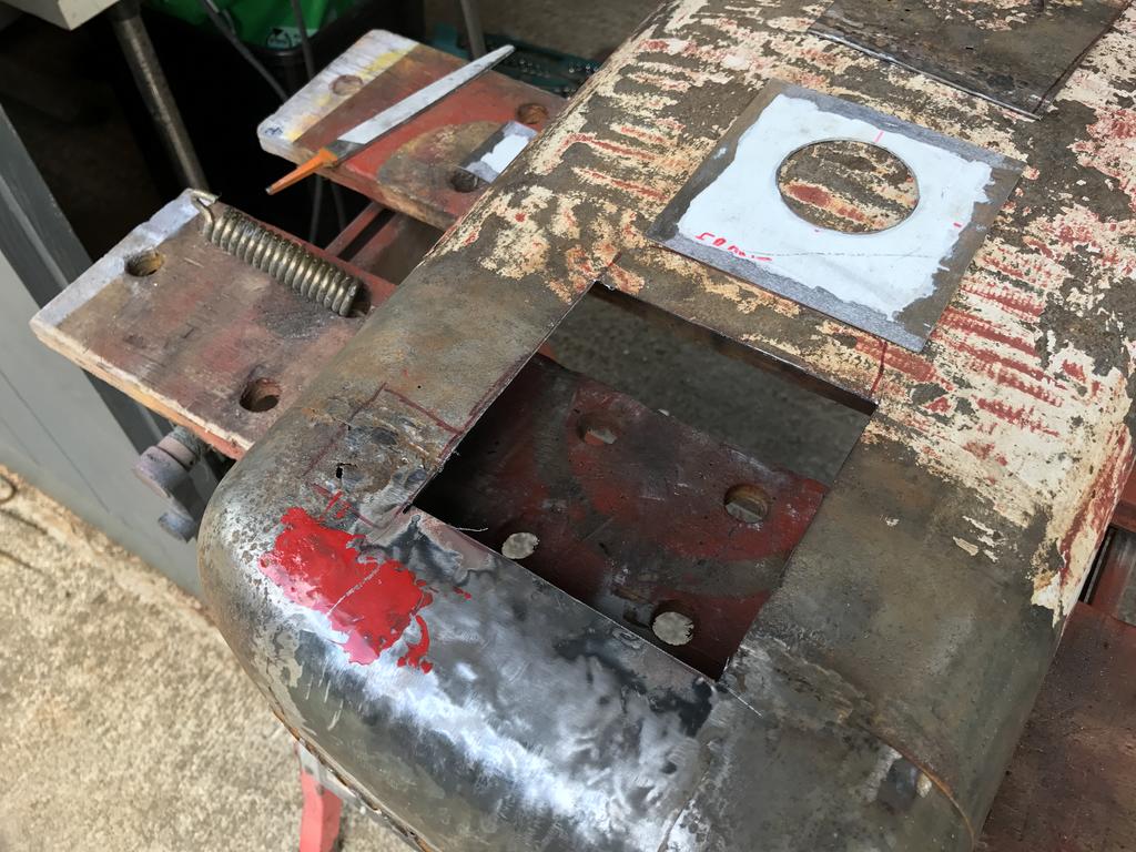
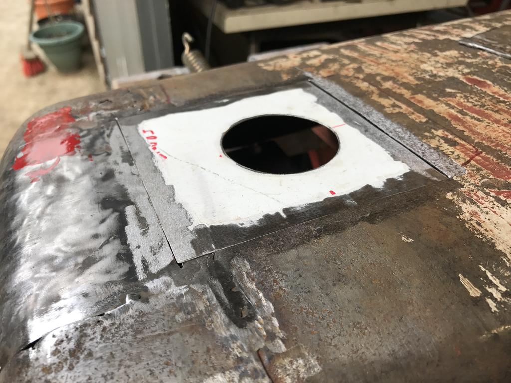
Checking everything lines up as it should.
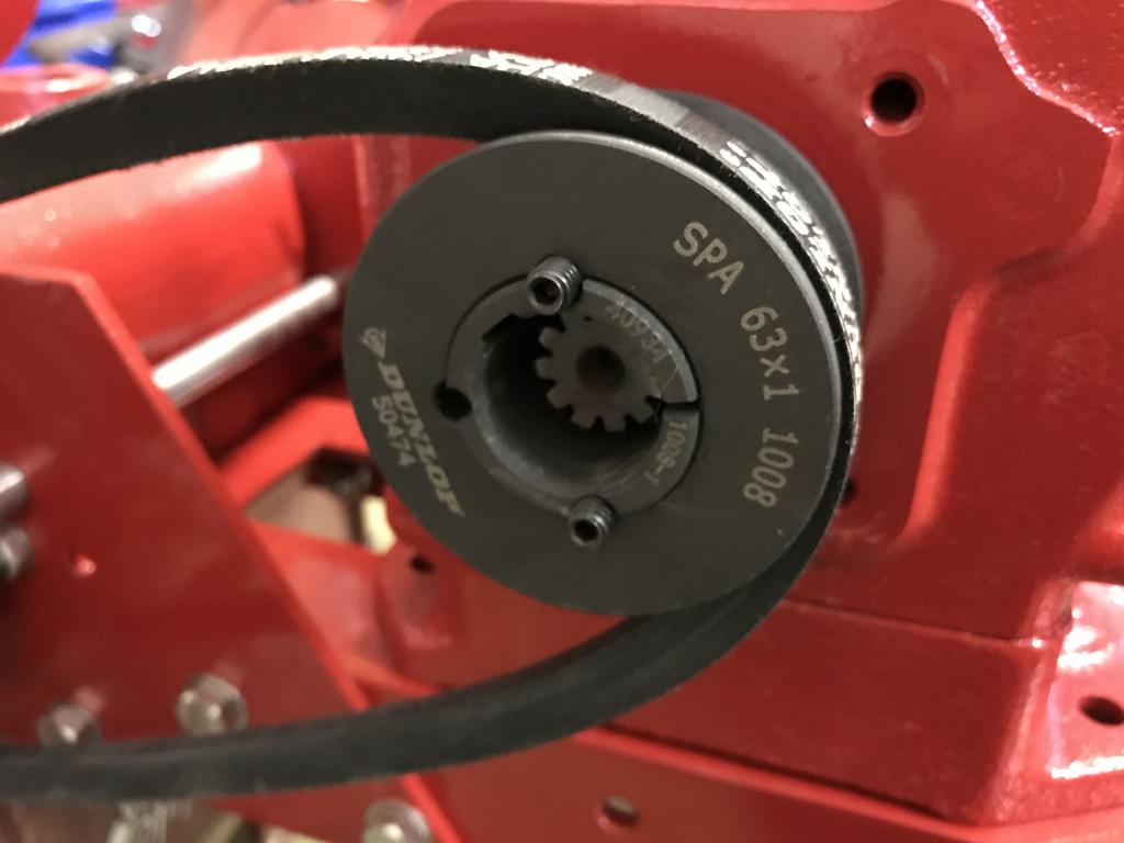
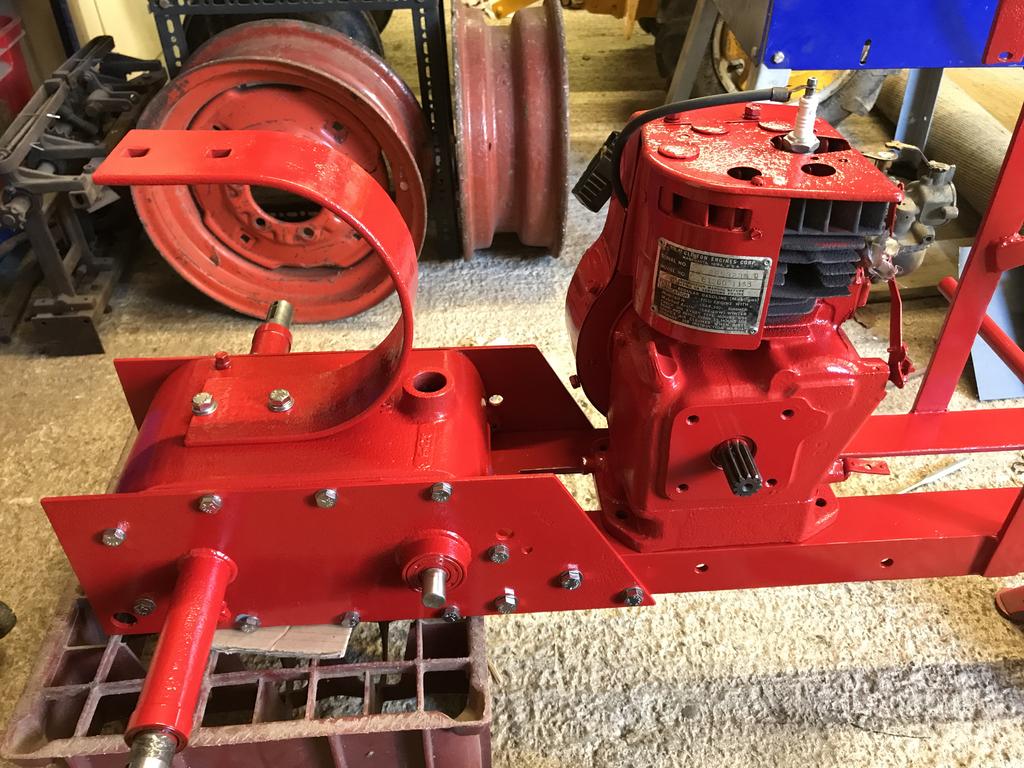
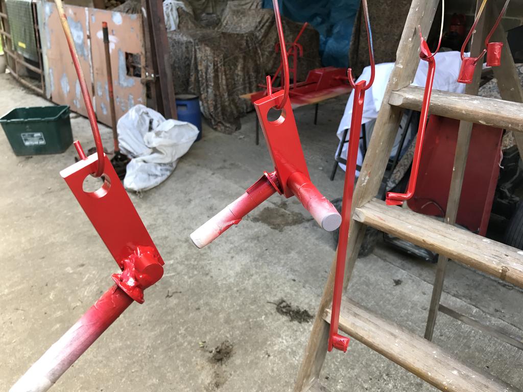
The idler set up that we made, one problem we have had is getting the belt to stop spinning when the pedal is pressed. So far we have not been successful
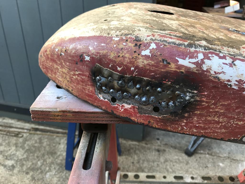
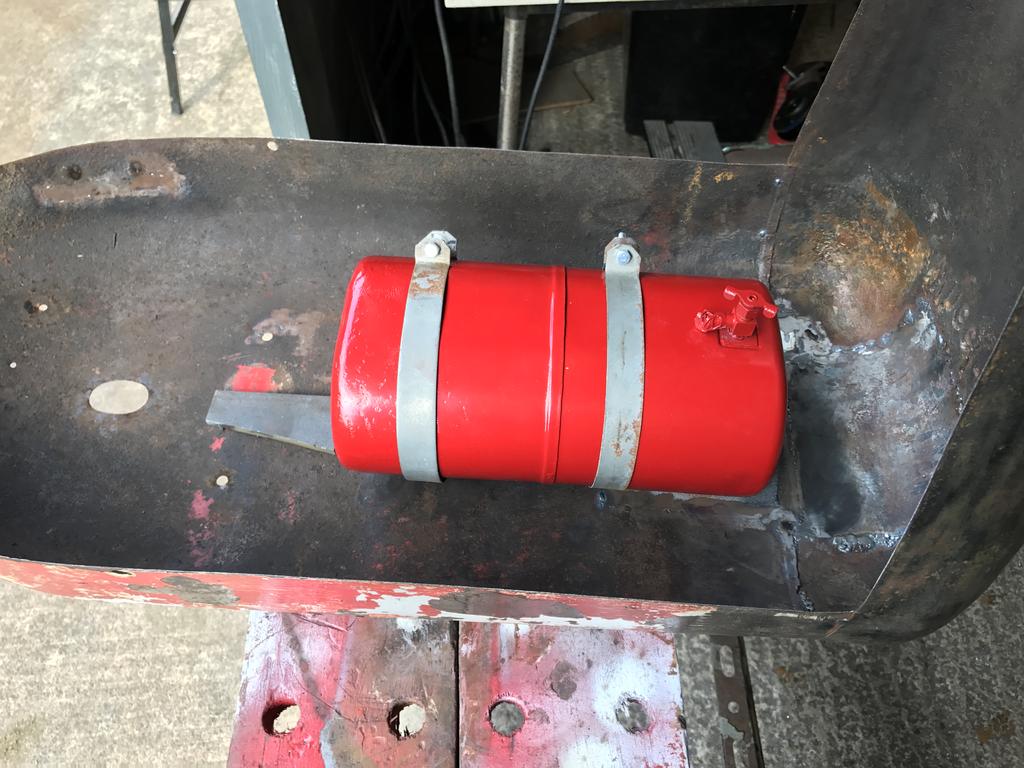
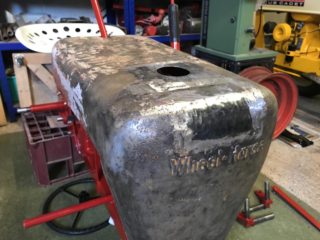
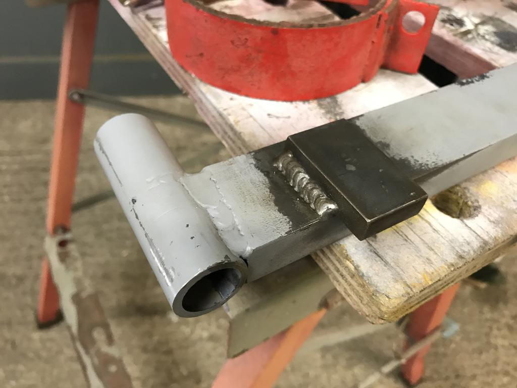
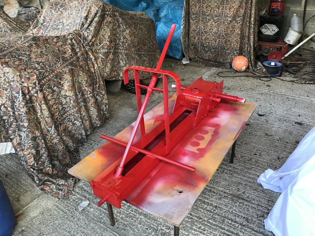
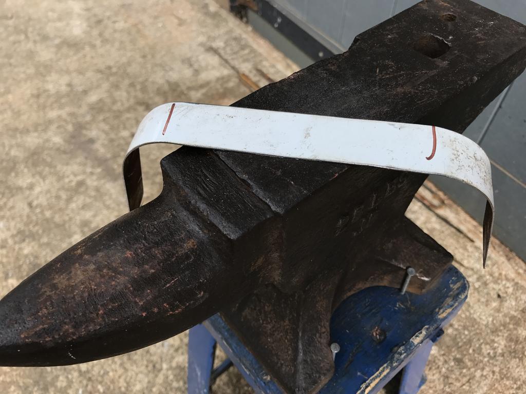
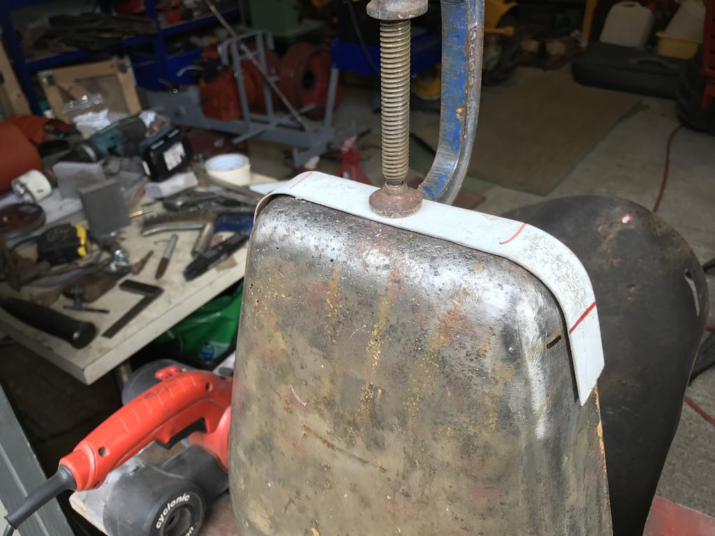
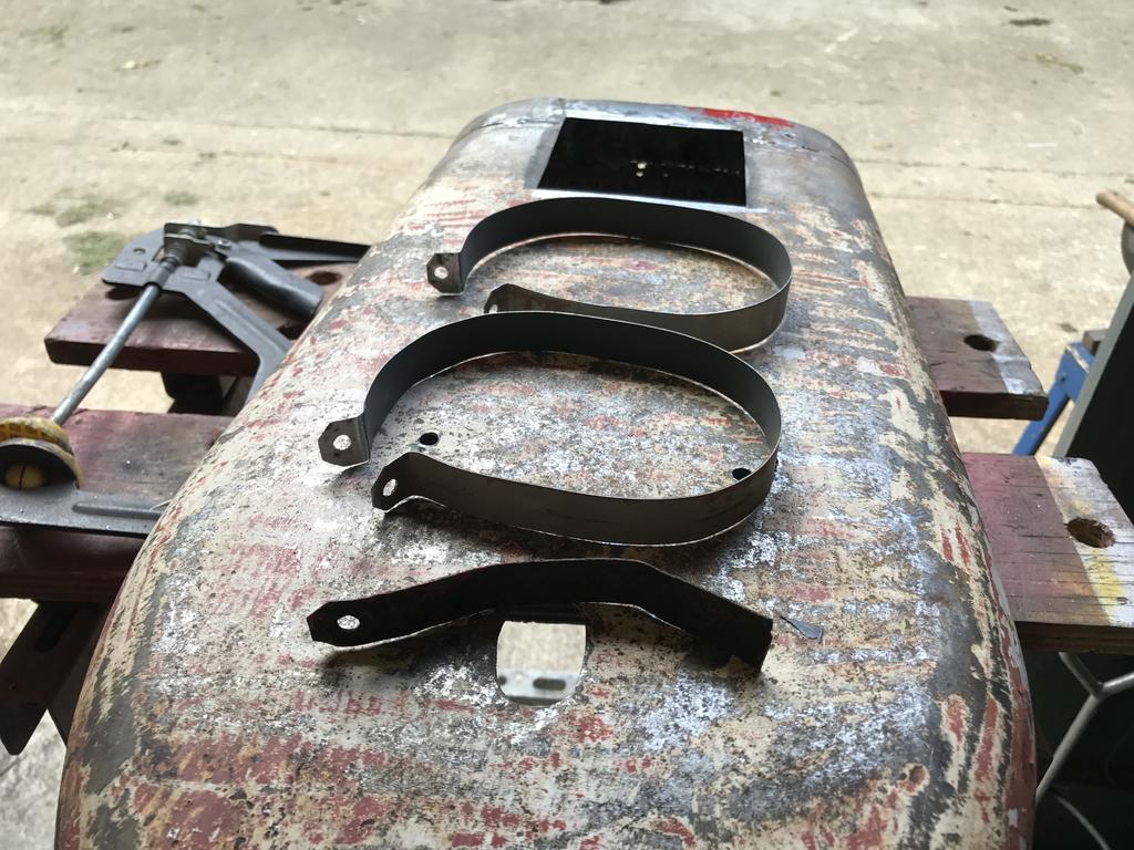
Newly made tank straps welded on and working.
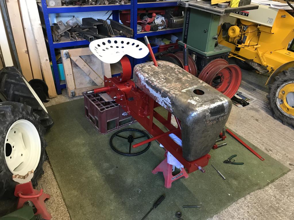
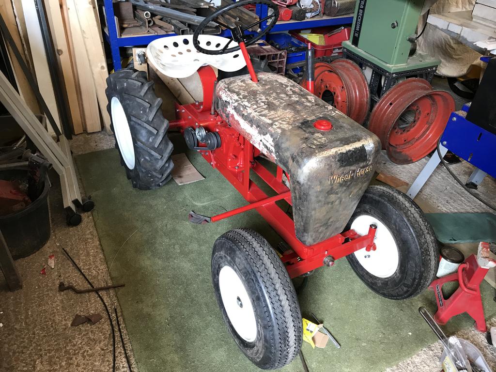
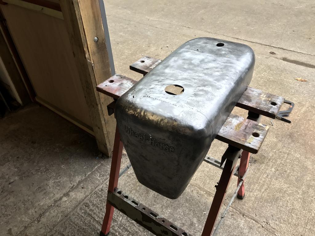
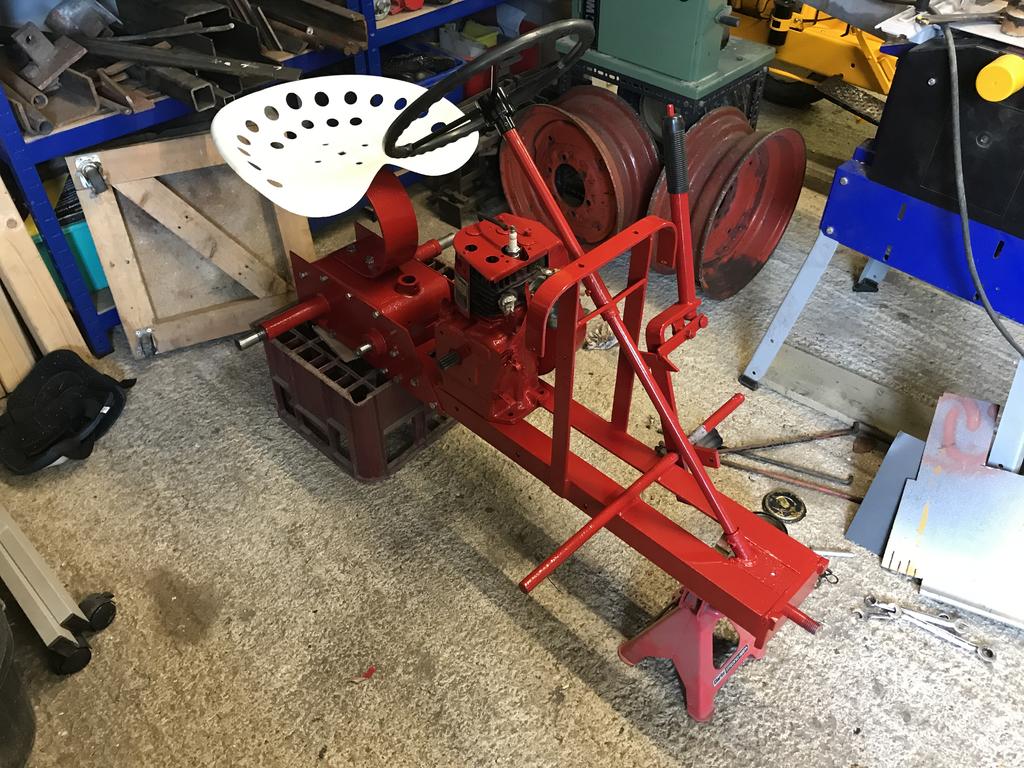
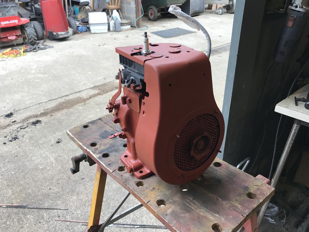
Looks more like a tractor now
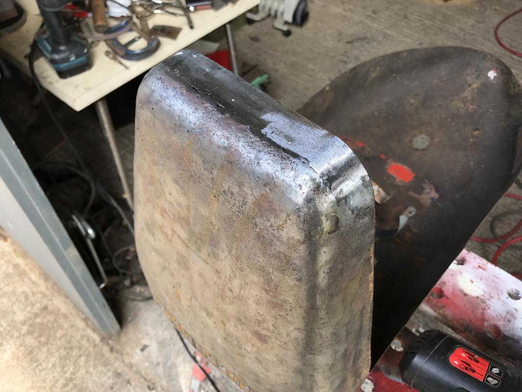
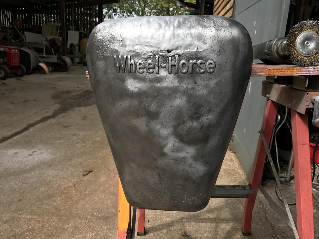
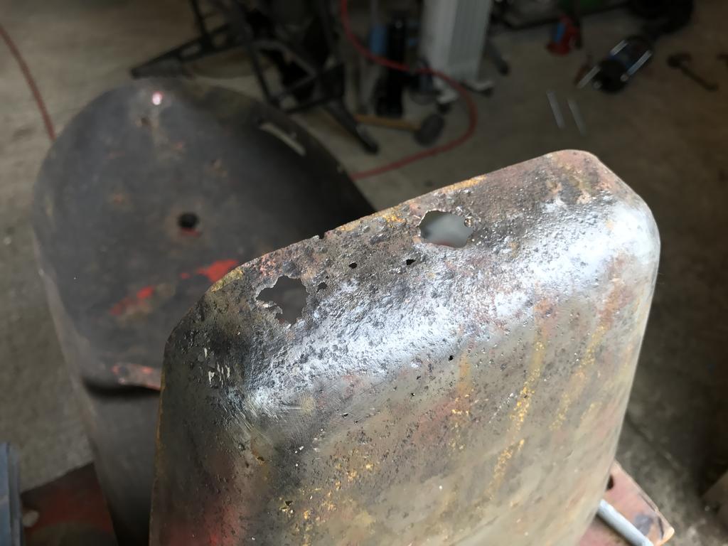
The hood is now rust free and after lots of panel beating its fairly straight.
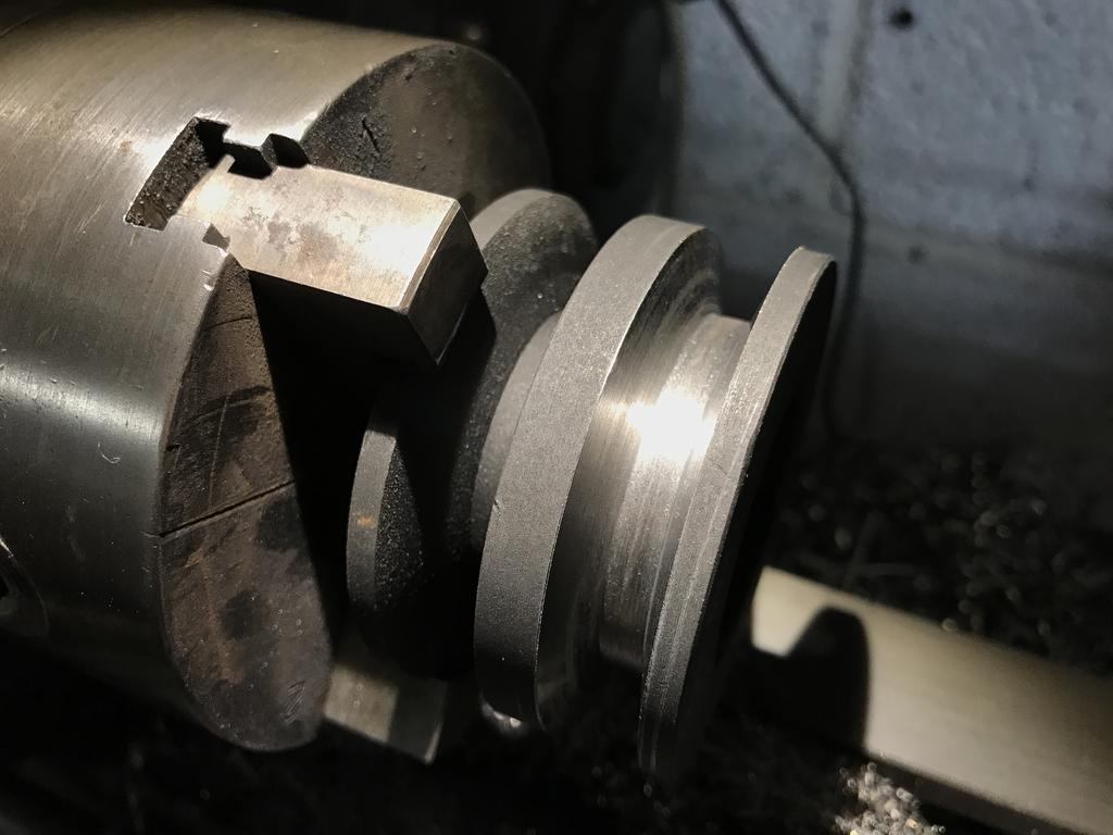
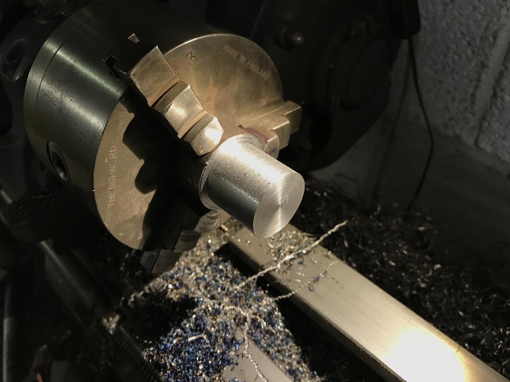
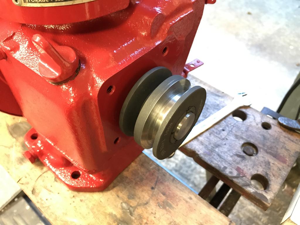
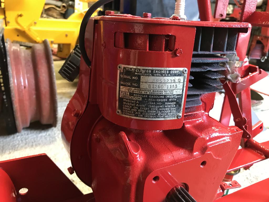
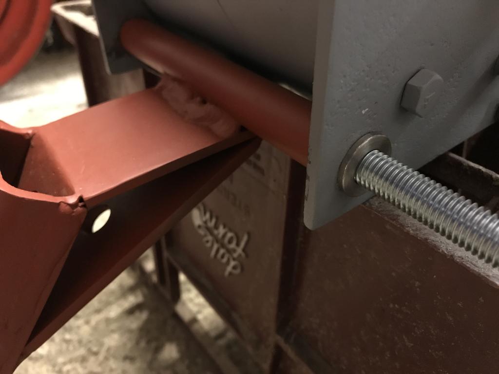
The engine pulley was next on the list, i bought a taper lock one but this came with a few problems, The engine shaft was geared and it was also not long enough the slide the pulley out to line up with the transmission pulley. I turned a new belt groove first
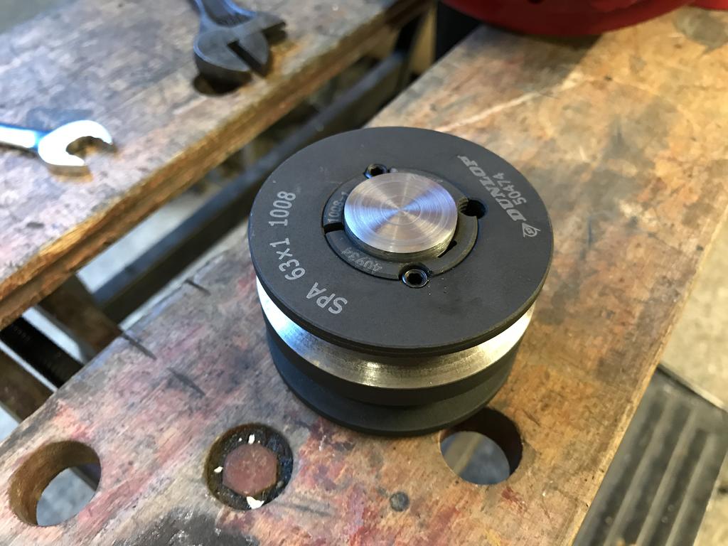
A small test for alignment.
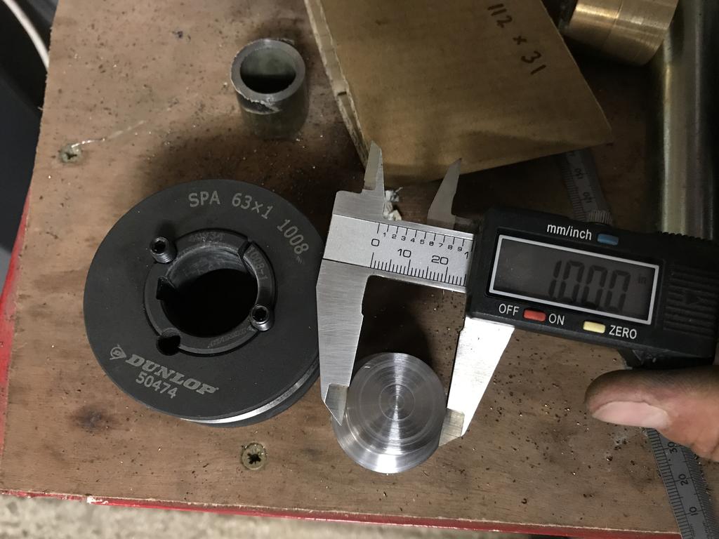
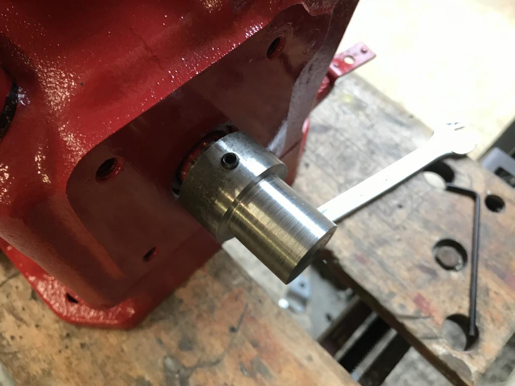
The above image shows the issue. the taperlock bush is an 1'' ID but the shaft was about 11/16" so I made a bush.
The first bit turned to 1"
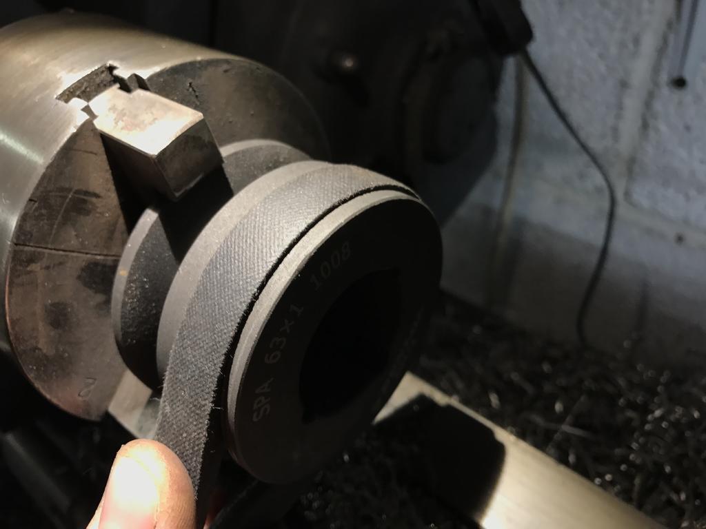
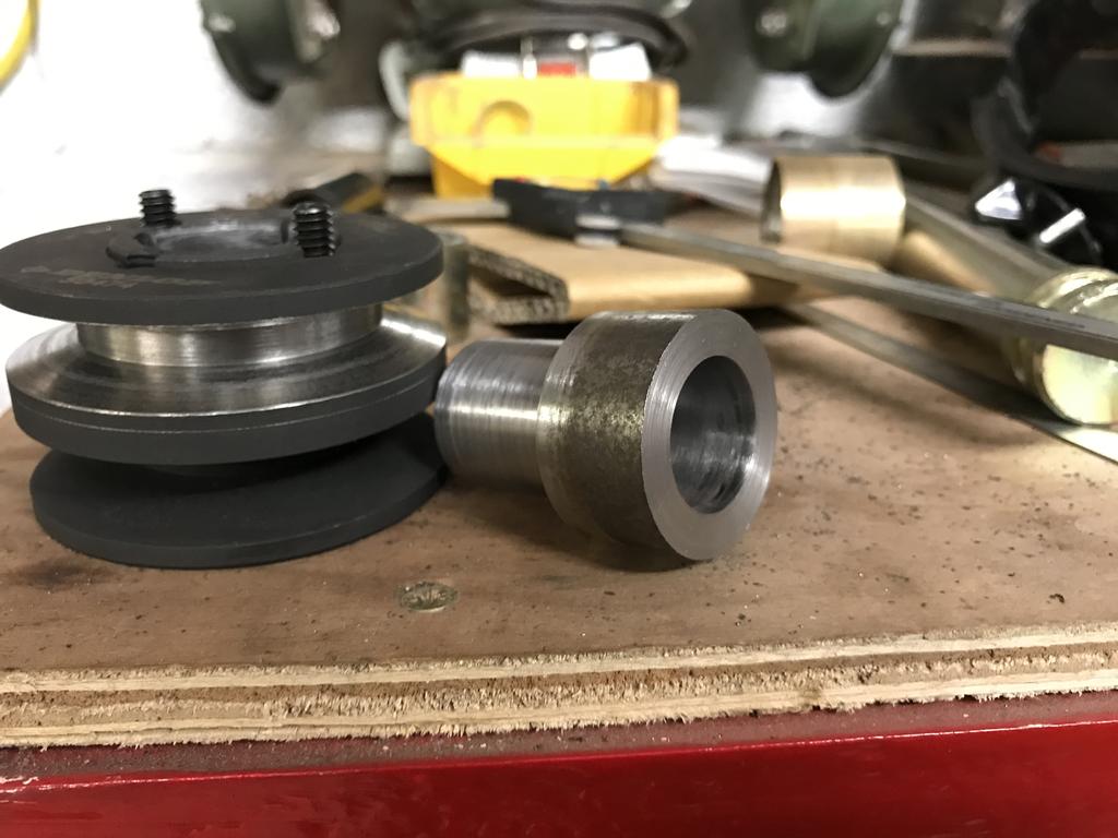
Then I bored the inside out to fit tightly over the engine shaft.
A couple of grub screws with tapered ends screwed to clamp the bush.
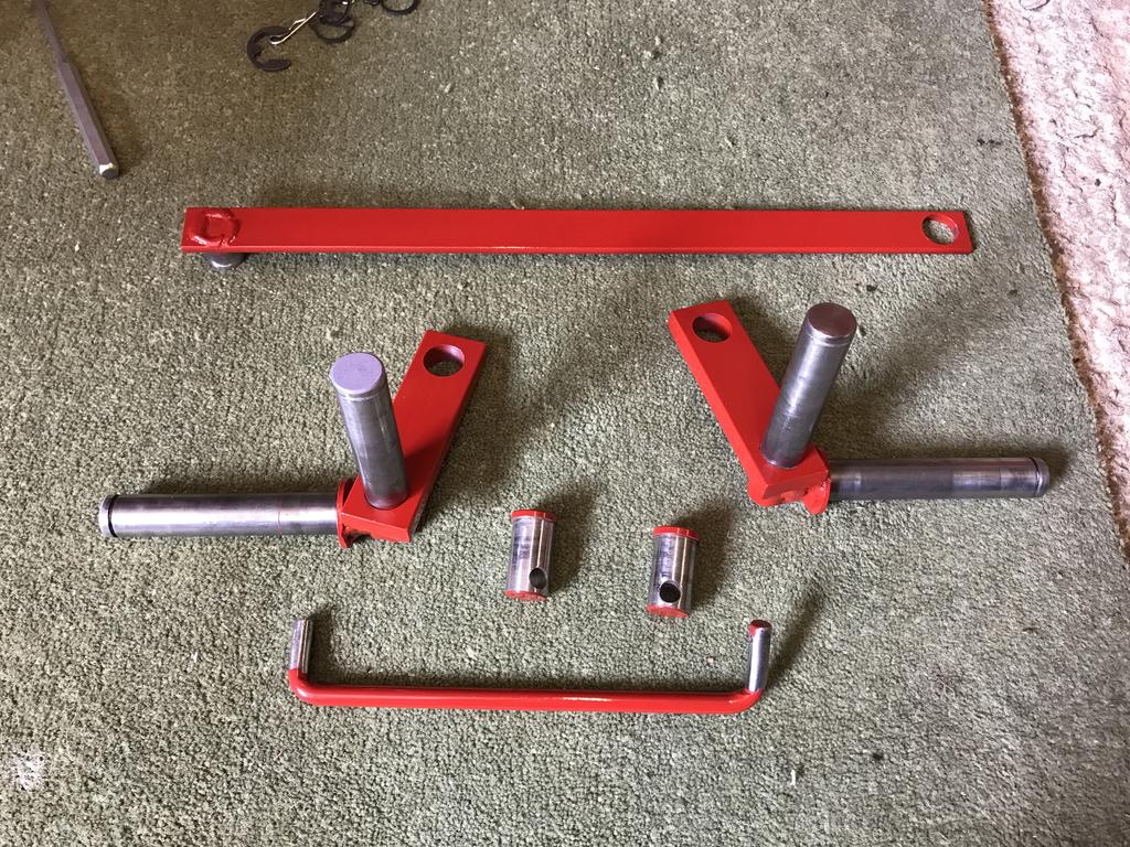
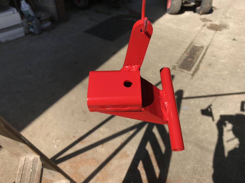
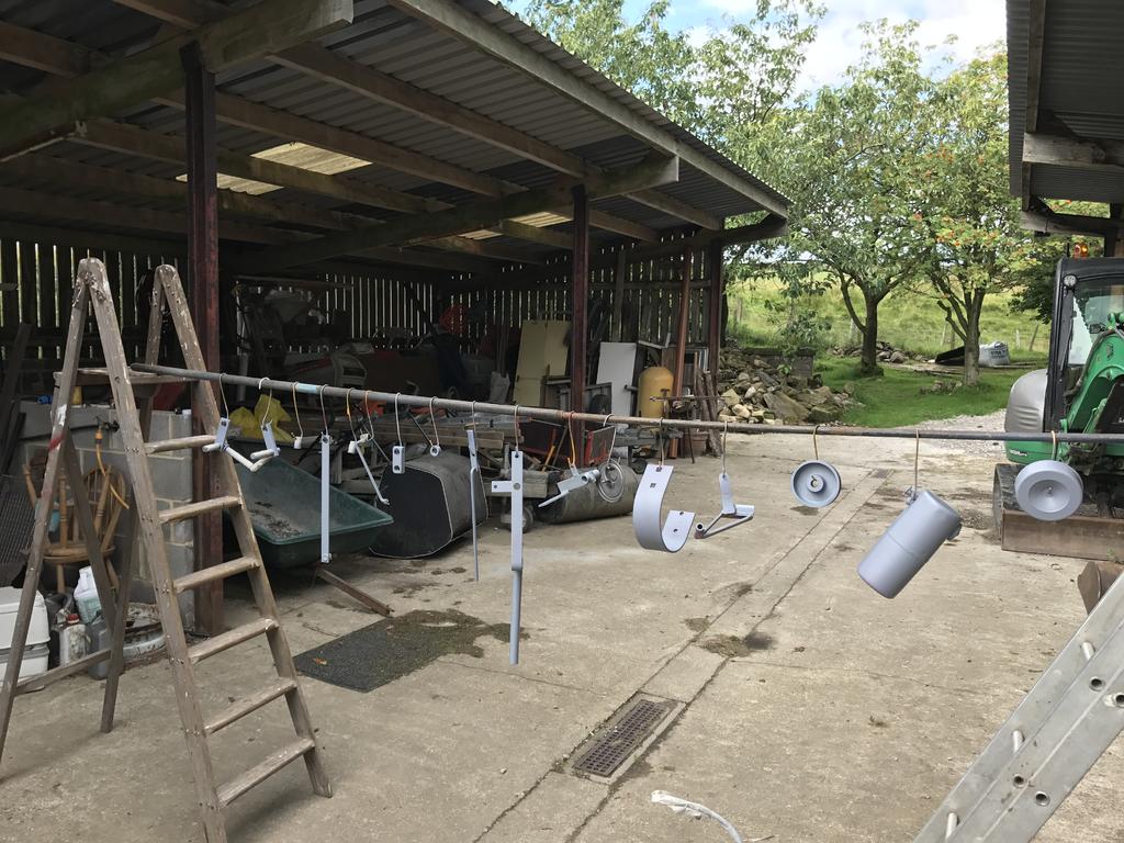
Due to the lack of large round bar I decided to use smaller round stock on the slot hitch, to get around this I turned some bushes for the transmission and used some M12 threaded bar.
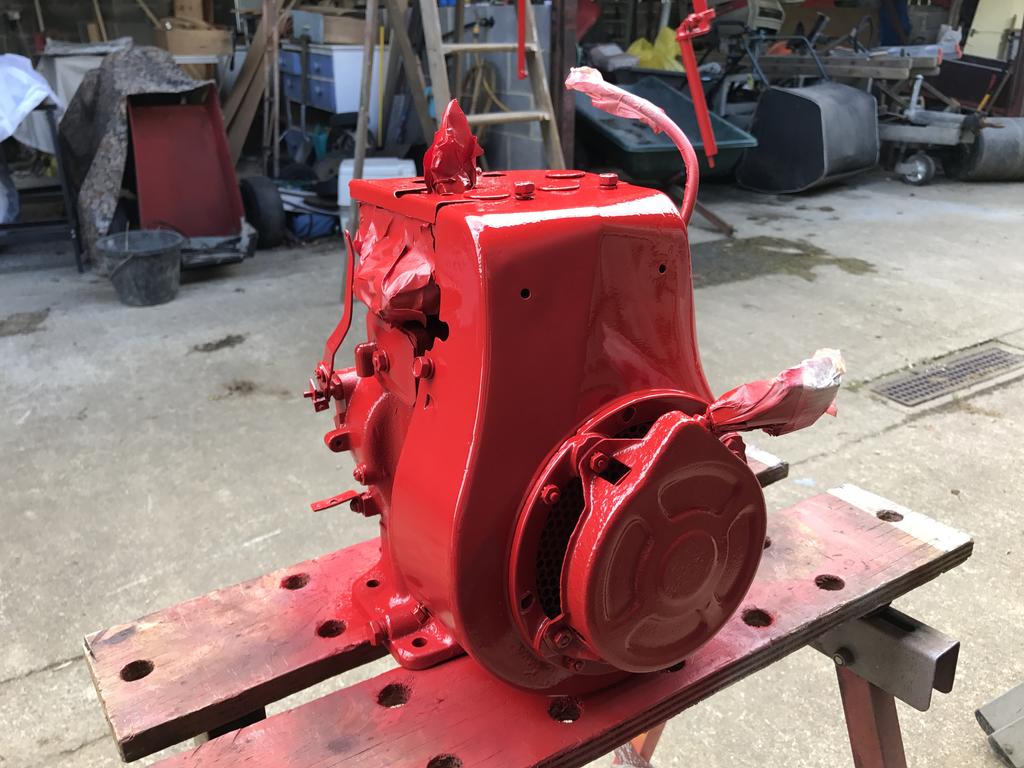
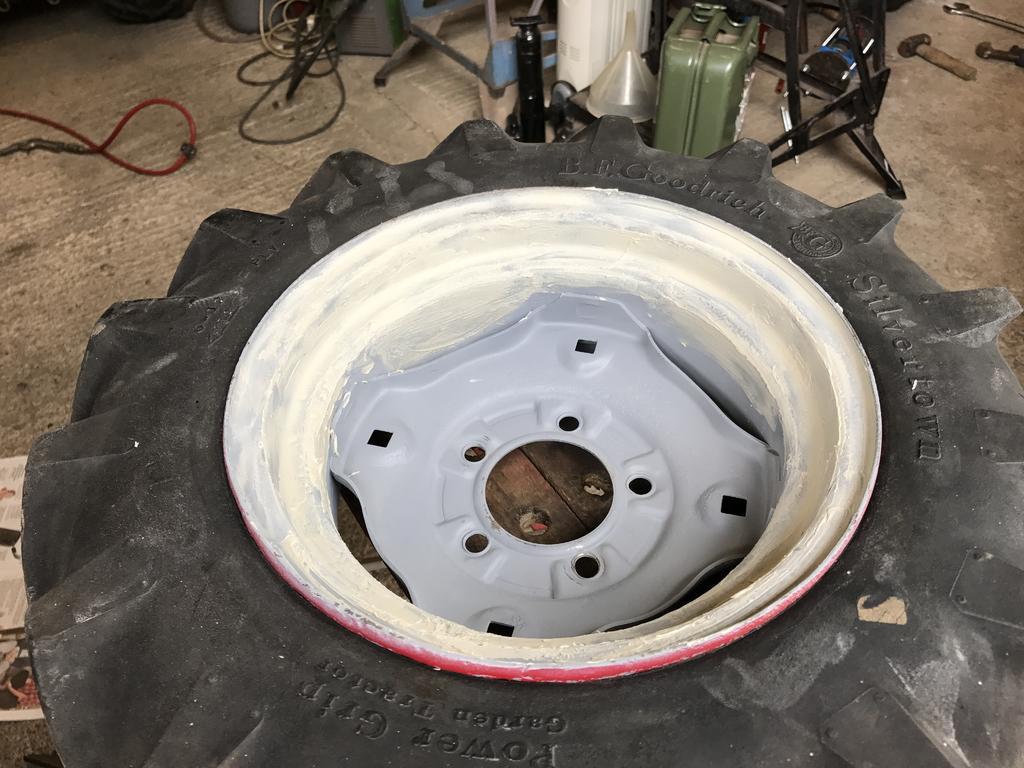
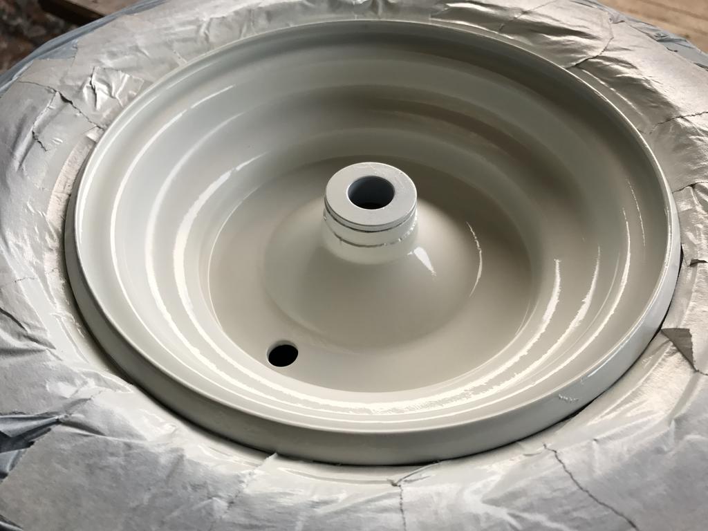
parts primed
And started the final coats. I opted to use cellulose paint and proper top coat thinners instead of enamel and standard thinners like I used on my cub.
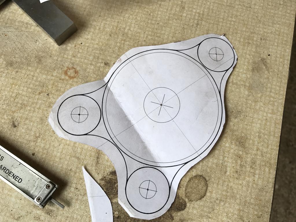
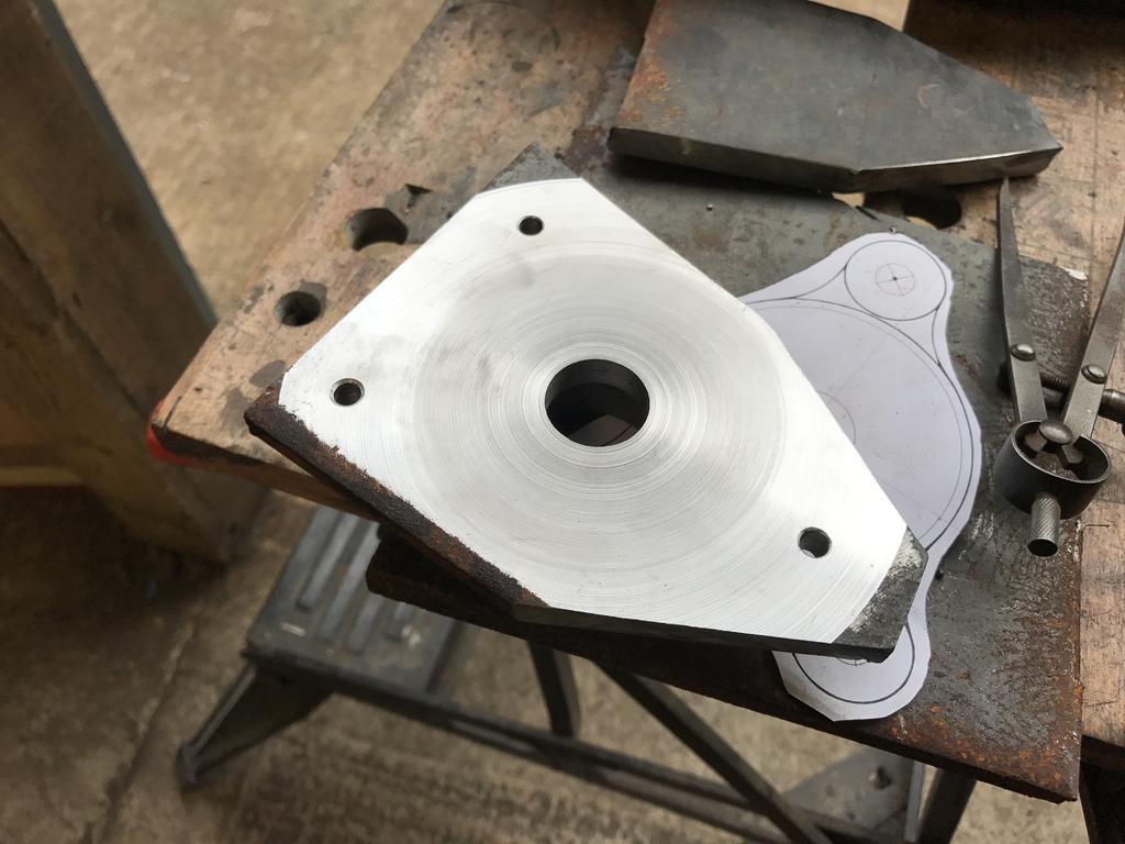
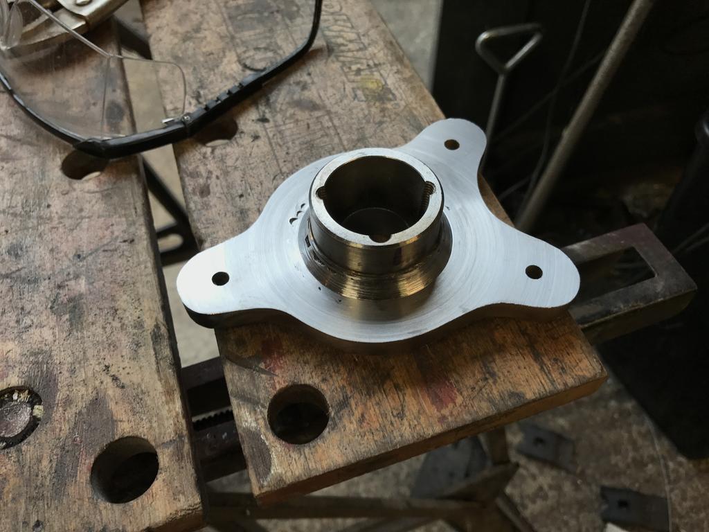
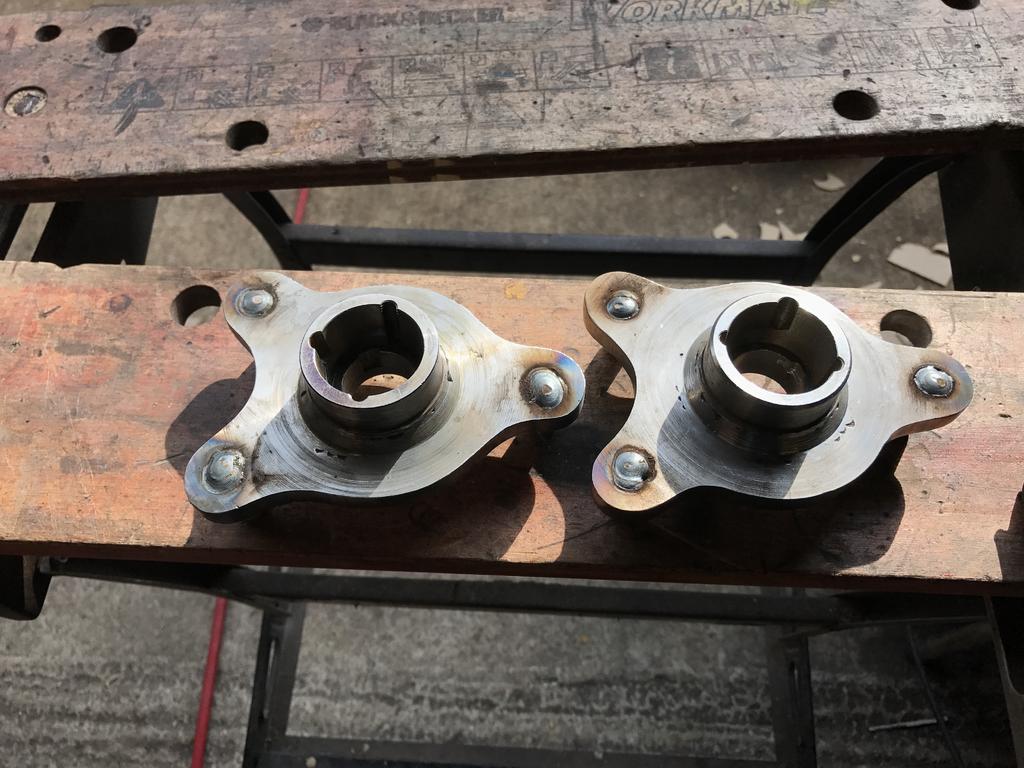
Now due to not been able to source any hubs, the old style or the newer ones we had to think long and hard about what to do. In typical fashion we decided it was probably easier and quicker to make our own
Heres how we started
My dad made a template on the computer of the original shape of the hubs
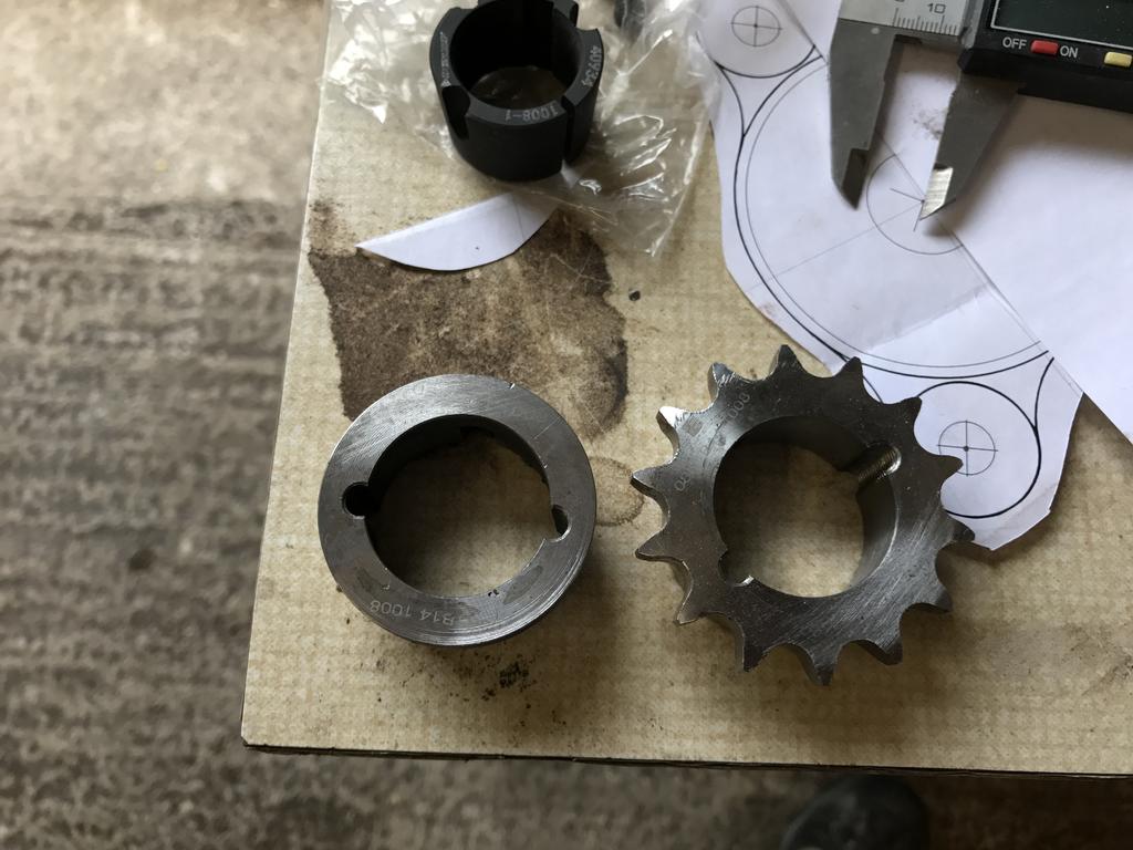
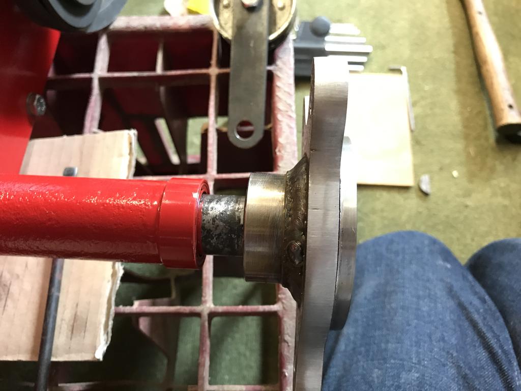
We opted to use taperlock bushes and sprockets, the first job was turning off the teeth.
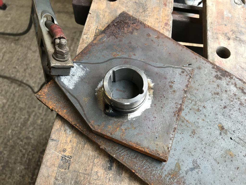
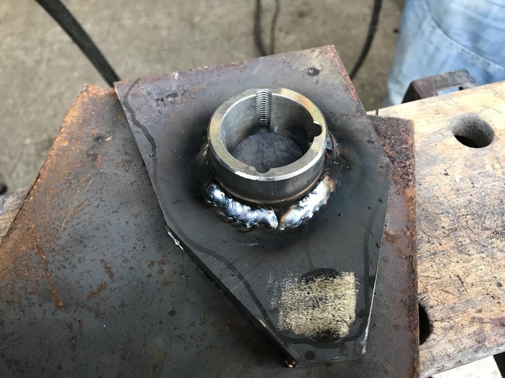
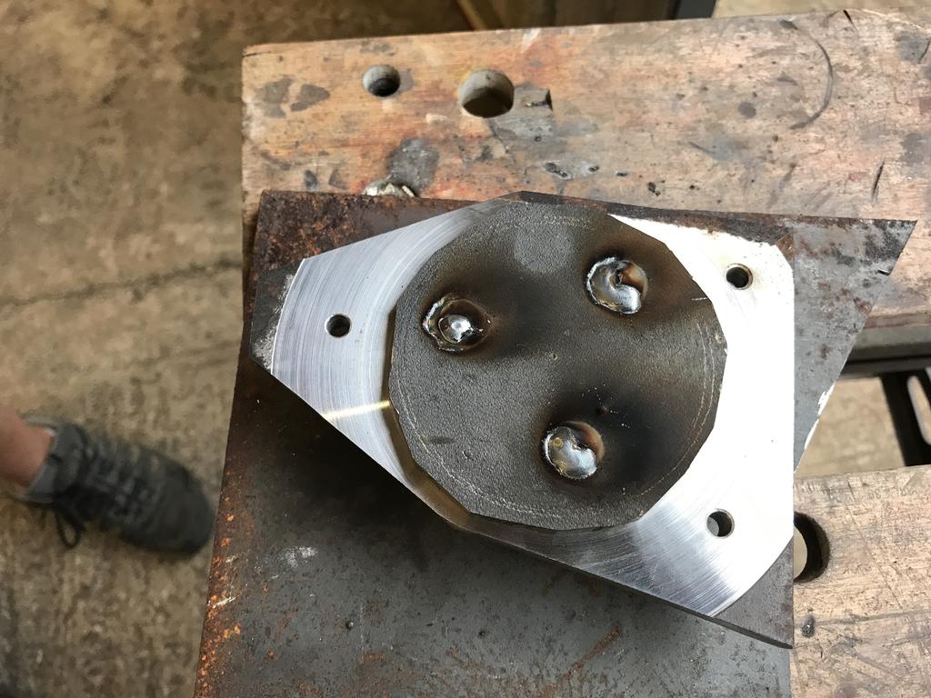
the rough shape was cut out of 1/2" plate and the 'sprocket' welded on.
Next I turned the face true, bored the centre hole to 1" and drilled the bolt holes.
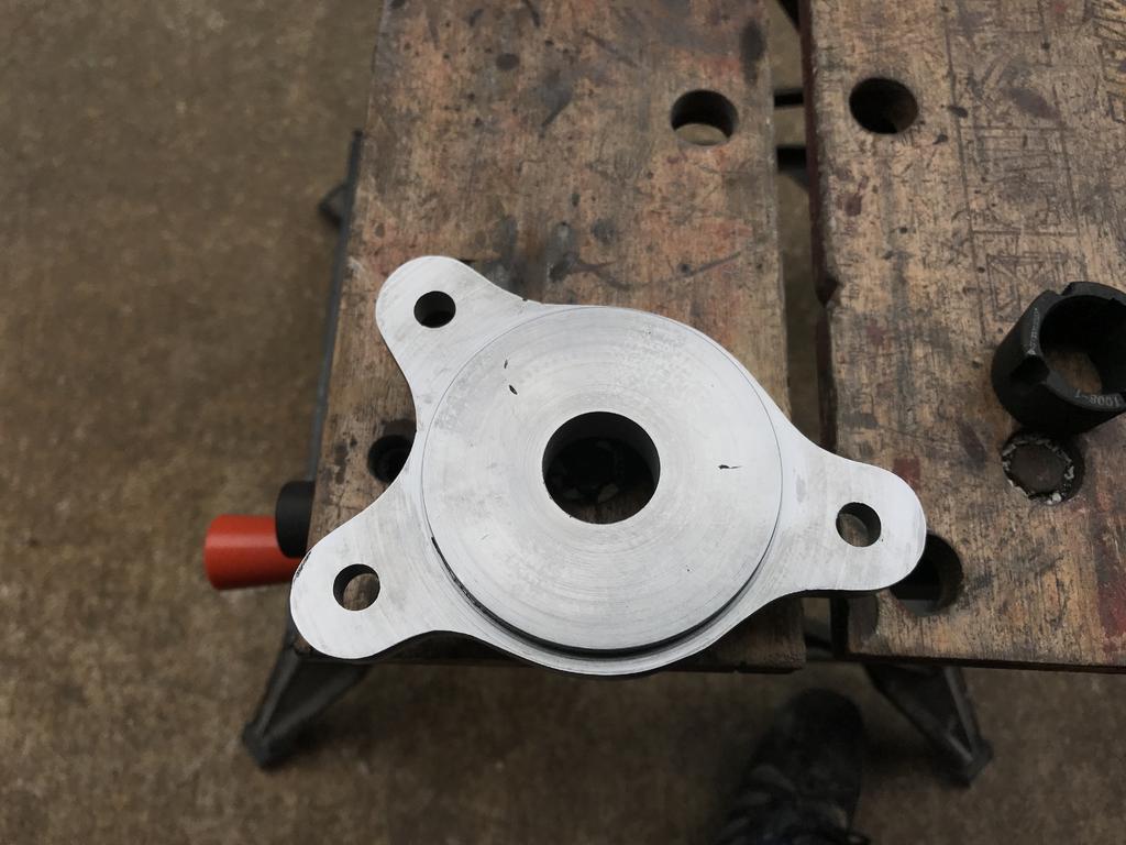
Then using a thinner piece of plate we welded the piece onto the hub, this is for the wheel to balance onto.
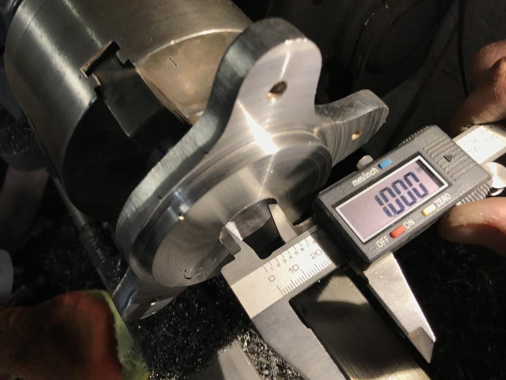
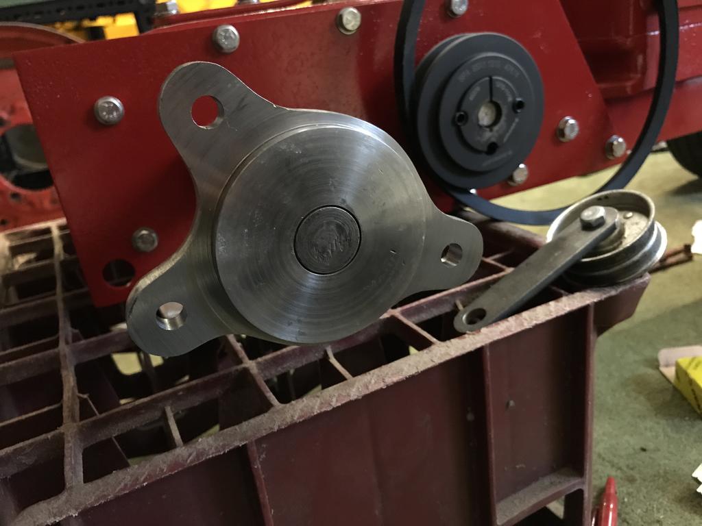
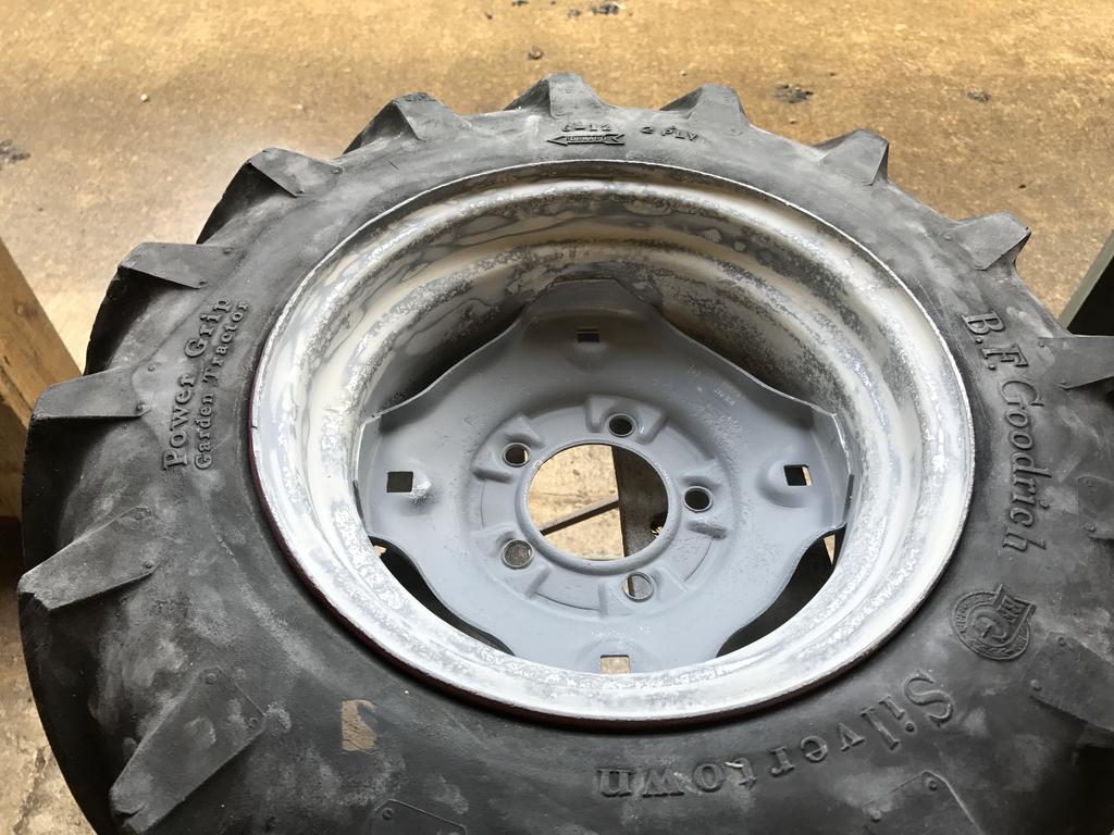
Next i turned the piece round and spent hours grinding and filing the hub to shape.
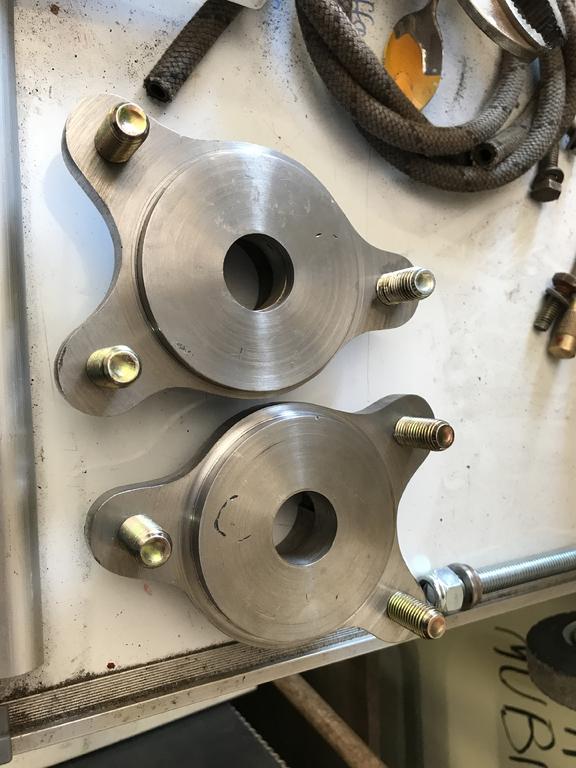
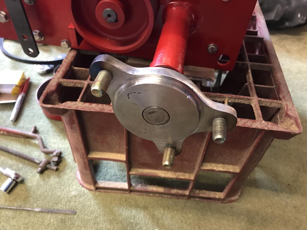
Its always been a pain trying to balance a wheel while screwing the lug bolts in so I opted to make my life easier and welded bolts onto the hubs instead and use wheel nuts.
How'd you get on with these, Paul. Just happens I've to go and see a couple of Wheel Horses. One sounds as if it is an R26. Got a B&S engine though. Non runner I think.
Could be an A-81/ A-51, they had a B&S engine. I think someone in the UK on RS was looking for one of those
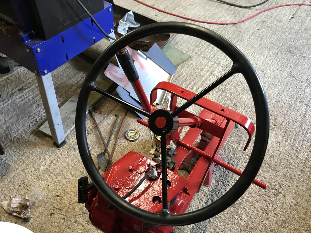
I like the way you've adapted the steering wheel. Neat job. And the making of the seals even better.
28 minutes ago, Alan said:
Good job on the tank Ewan. I have one of similar construction from a lawnmower which would fit under the hood of Half a Horse if unsoldered and the non stepped end shortened in length. Might need a long range tank for the rally fields.
We often did seal mods at work if the original size was not available. Usually a thin steel sleeve pressed into a bore with the nearest standard size seal inserted. Sometimes went the other way and opened out the bore to take a larger seal. Depended on the job and what was available. Keep up the good work.
Cheers Alan, I was lucky that the engine I sourced from Chris had a tank with it as I would've struggled to find one that would've fit under the hood of the RJ.
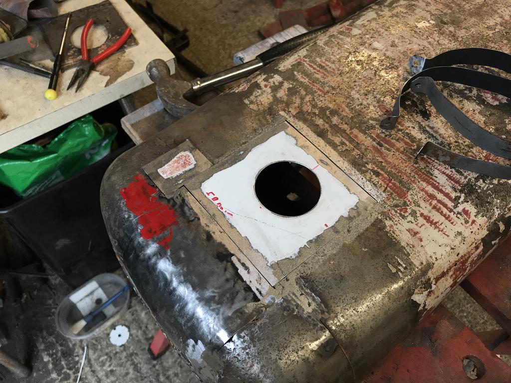
I tackled the fuel tank next which is a small size so harder to find.
As you can see the tank was gunked up, nothing was working to clean it so the only option to salvage it was to unsolder it and clean it properly.
In two halves.
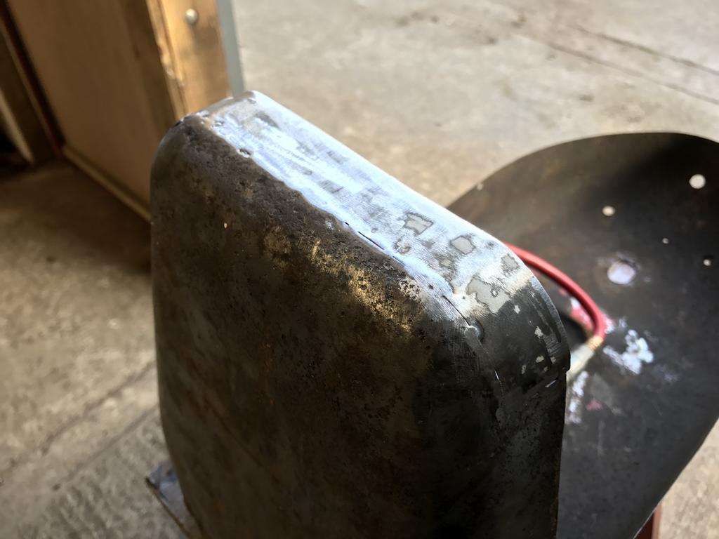
Immaculate now, ready to solder both halves back together, I also found some small pin prick holes which needed fixing.
I thought i'd try using silver solder for the first time, I had to get it red hot in order for the flux and solder to do its job, the solder flowed into the overlap perfectly so i'm happy that its sealed properly.
The cap had a tab missing so I fabricated a new one and soldered it on, Has anyone got an idea about what the seal would've been like and where I can buy one?
Plenty of stainless bought for the reassembly.
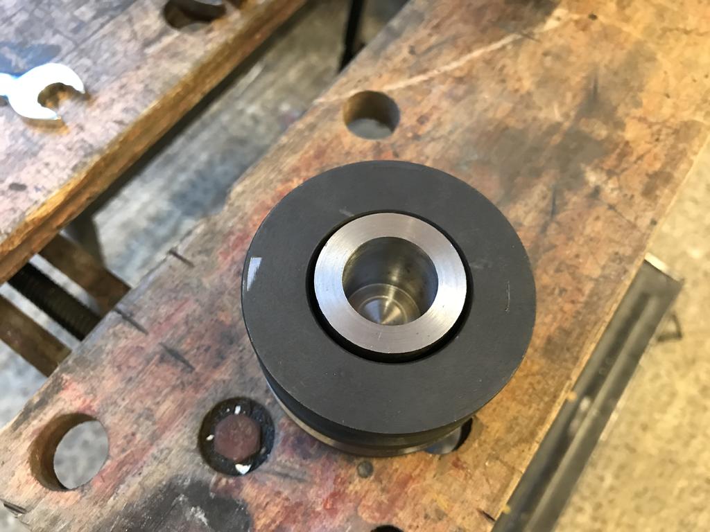
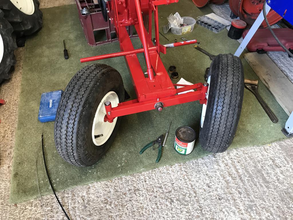
The original axle seals were missing and you can still buy them at $20 a piece, that wasn't going to happen so I turned some steel tube down to the correct dimensions and bough some seals to push into them. They fit snugly over the axle so hopefully they'll work


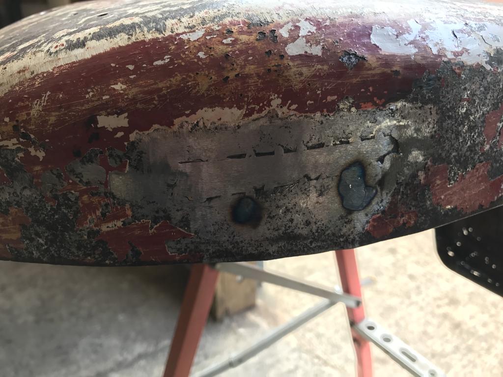

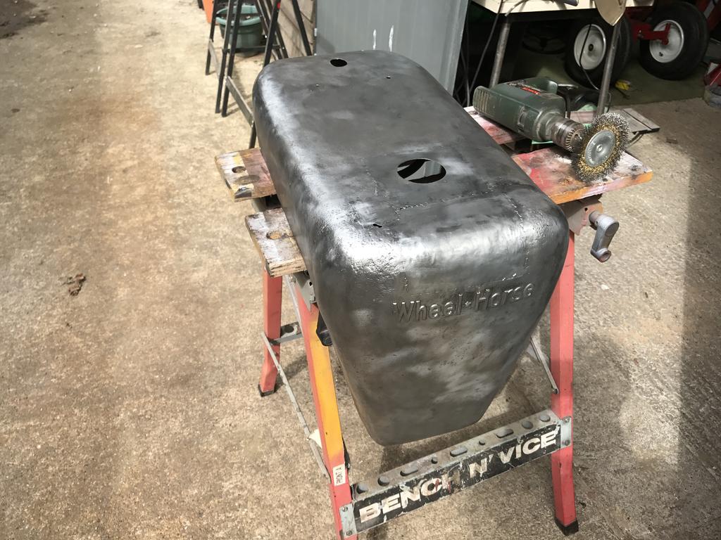


 A hood with that many holes would usually finish up in the skip.
") If they were easier to source this sure would've been in the skip, but it shall be saved
If they were easier to source this sure would've been in the skip, but it shall be saved 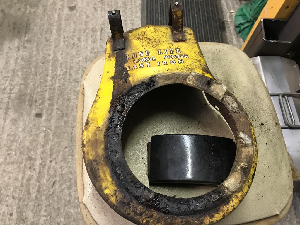


")


Wheel Horse RJ-58 Restoration
in Step by Step restoration
Posted
Thanks Chris, I did read that the cover helped with the belt, thats next on the list of parts to make") I think I may take the pulleys off and give them a polish next.
I think I may take the pulleys off and give them a polish next.