Here's a manual. Comes as a folded booklet so some views are upside down an sideways but it can be printed and folded if you want one to go with your engine
I was trying to post the ENTIRE thread but it would not allow me to do it with ALL the pics and gifs copied into it. At least we have the vitals posted!
And Thanks Again to Laserscottman for doing this in the first place. It was by far, the most viewed thread on our old forum.
Testing check valve
Once it's all back together use a piece of fuel line connected to the inlet and try to blow in it. It should only allow air to pass when the primer button is pushed. If it's allowing air to pass otherwise it's not sealing and therefore not check valving.
Some carbs allow the cover to push down on the little arm ever so slightly too. I typically don't use a paper gasket along with the diaphragm but I do add one when this condition occurs. It's an easy solve compared to trying to bend that little arm.
I had one of these shipped over the pond and thought I'd might never see another.
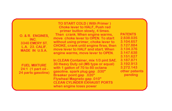
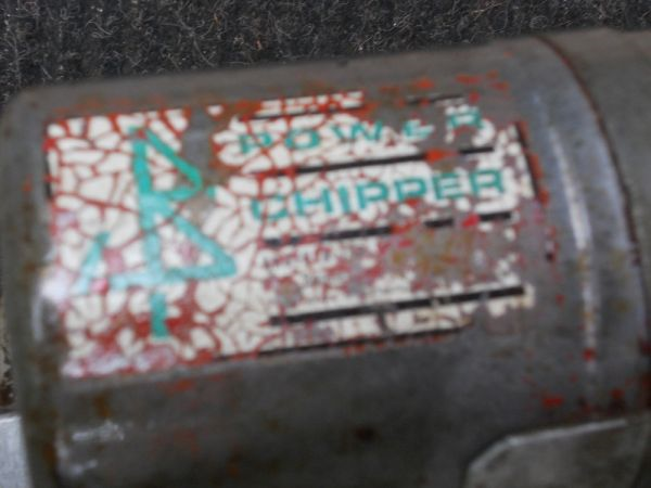
I also started to try and remake the labels for when ever I get around to painting it. Here are some that were made using Microsoft paint program so the edges are not as crisp as I'd like but should work if you want to get someone to make them for you.
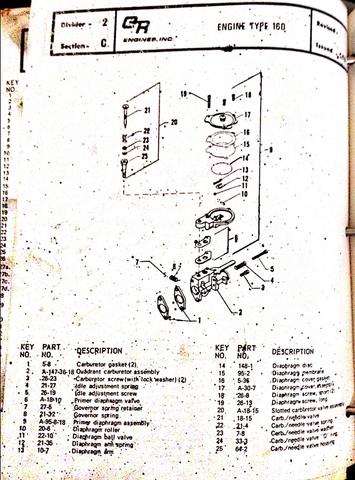
Yes, the disc sits directly on the arm. The clear check valve gasket sits against the diaphragm body so it valves the little hole going to the carb body. Here's a carb drawing showing all the parts.
The little bearing ball is a must have so check your carb to make sure it is still in there if you think it might be missing.
No worries on ANY questions, that's why we're here!
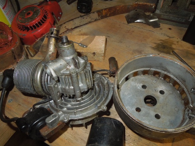
Now the last cover for the generator can be removed from the engine.
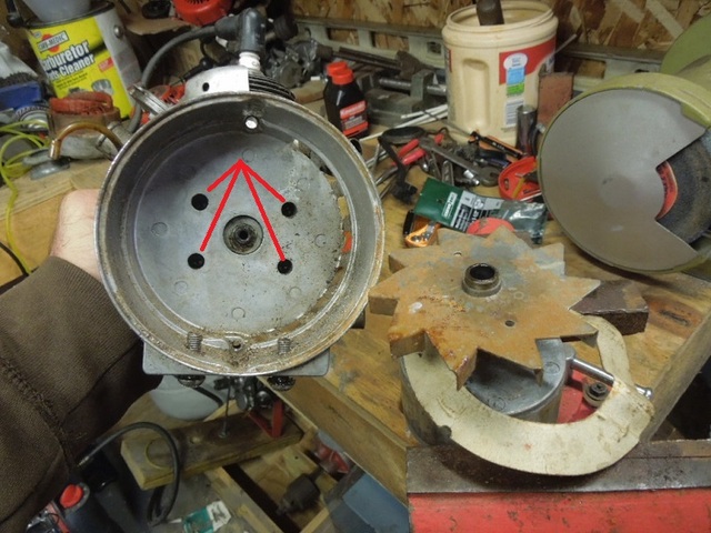
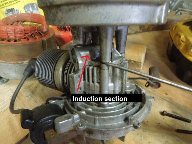
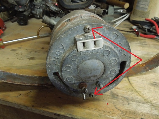
Remove the 4 screws holding the cover to the engine. Be careful after removing those screws! The induction section of the engine is also held on by these screws and can easily separate from the engine. There are roller bearings inside that can easily fall all over when that section of the engine is removed. Not usually a problem if you're ready for them but a real pain searching for them when they fly out and you're not ready.
I used a small screwdriver to separate the pieces without removing the induction section from the engine.
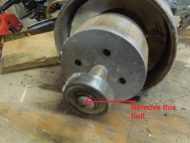
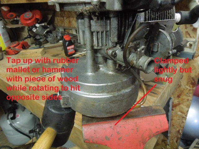
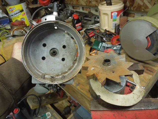
Now the magnet core which spins inside the windings needs to be separated from the engine. First remove the bolt holding them together
I clamped the core lightly in a vice and taped the edge of the generator cover with a RUBBER mallet while holding the engine and spinning it from side to side to hit opposite sides until it came loose.
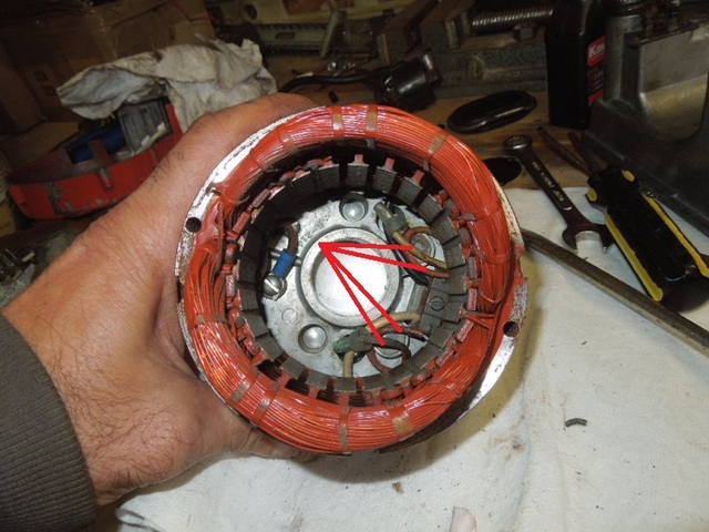
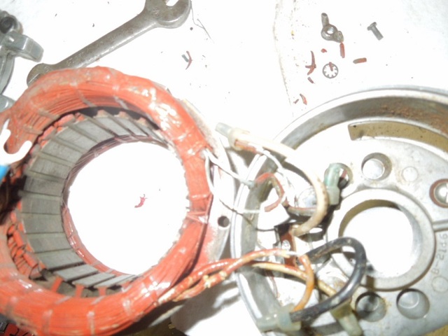
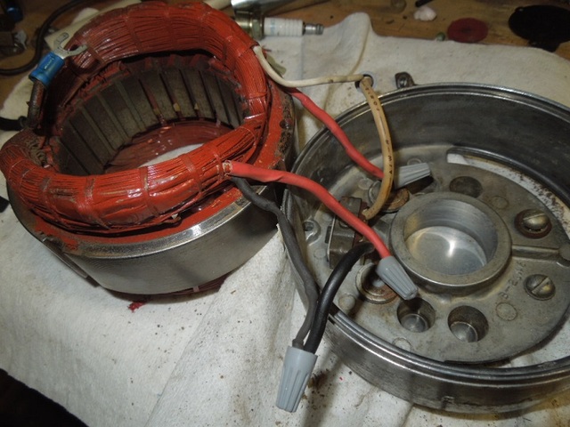
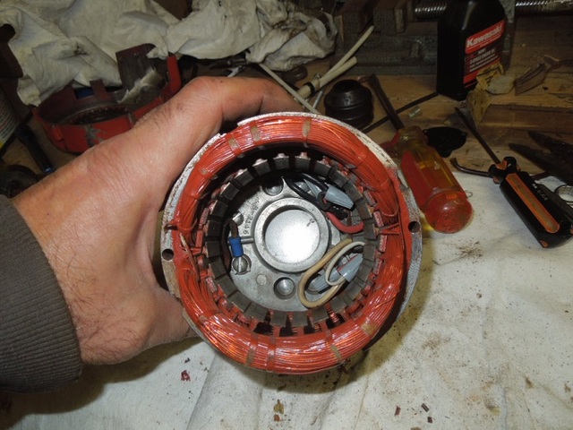
After separating the parts, I noticed that the wire insulation was dried, cracked and parts missing. This will get even worse if the components are pulled apart but they can be fixed.
Here is a better view of the cracked insulation
Using heat shrink tube, the wires were repaired and connected back together using small grey wire nuts
All back together and wires tucked down and out of the way
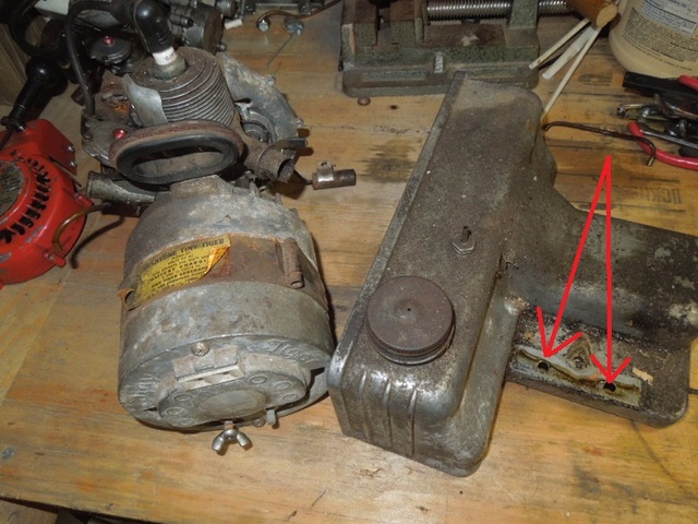
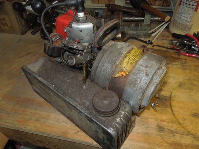
2 screws on the bottom are taken out to remove the generator and engine from the tank.
To separate the generator from the engine remove the 2 screws which hold the generator parts together.
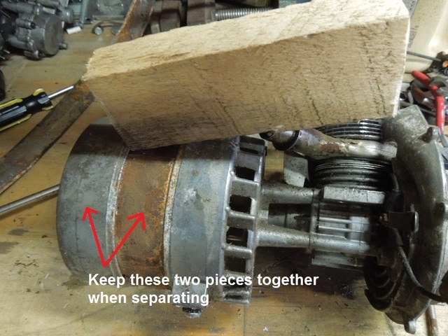
First remove the band if there is one which just clips on and off. You can see the band in the first pic.
Be careful when separating the components. The winding section (middle) and the outer section with the AC plug need to be removed together since they are wired together. I used a piece of wood that was near by to tap the sections loose.
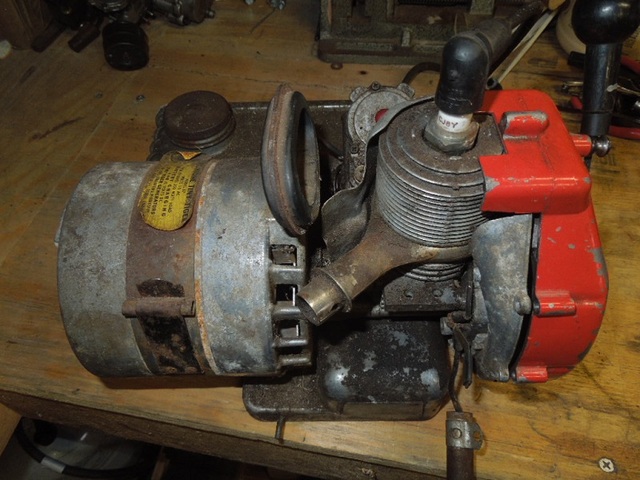
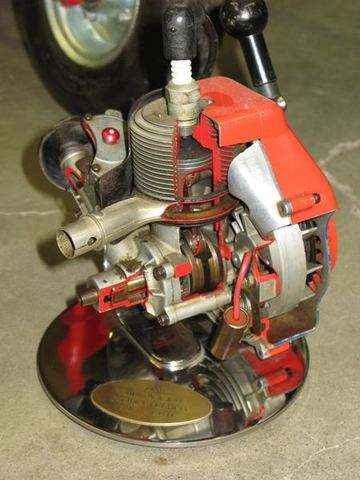
Had thiis TT 350 around for a while and decided it was time to clean her up. Took some pics through the process to show a tutorial on how to take the components apart, what to look for and how I repaired it.
Same process for the 300 model which seems to be a more common unit compared to the 350
The one I posted is not mine either, just a web pic but definitely thought about doing one of these myself. Shouldn't be too hard using a band saw and a Dremel cutoff tool.
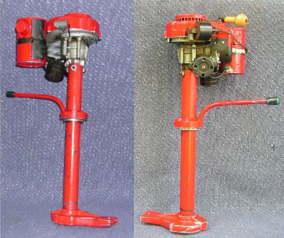
Very nice job saving another piece of O&R history. Your Power Pole has the removable powerhead to be used with other attachments. The only other one I'm aware of at this time is the outboard but hopefully we'll find others too. Some of these have a different engine mount and are only used as snow throwers. If you search "Power Pole" you can see Webhead's version is like that. You'll also find a video of mine throwing snow, they actually work very well
I do have a spare cover like you can see on the water pump. Just hate to cut it. The manufacturer cut the bottom off to mount them on the chainsaws since the tilt of the engine does not leave enough room for it.
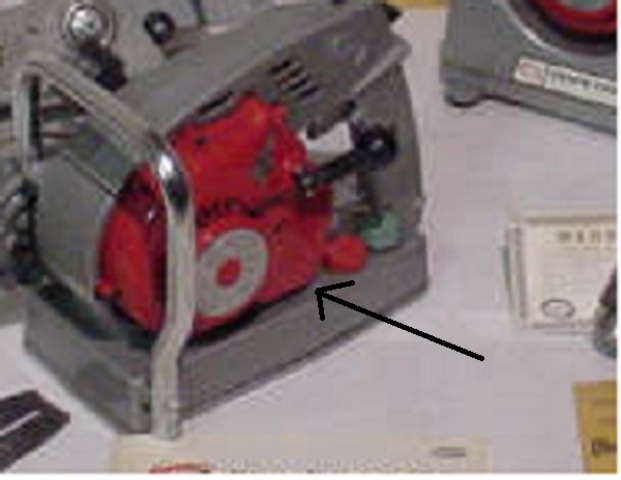
The saw has been done for a while but I'm still undecided about cutting a cover to fit. I do like the finished look of the covers but doesn't look too bad without it. Here's a blow up pic of the chainsaw cover
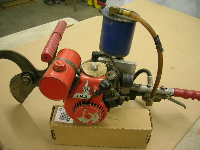
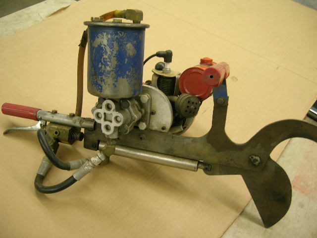
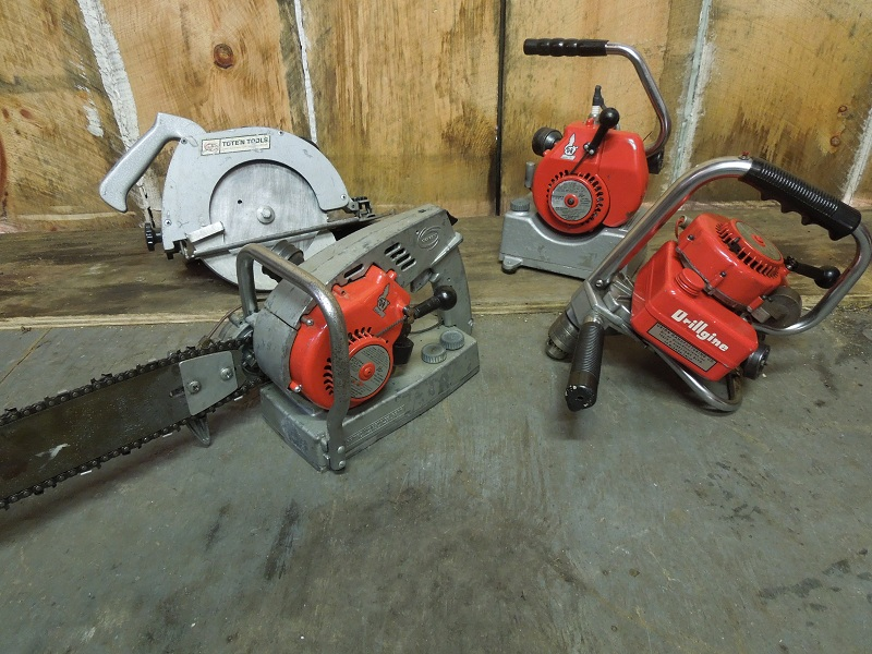
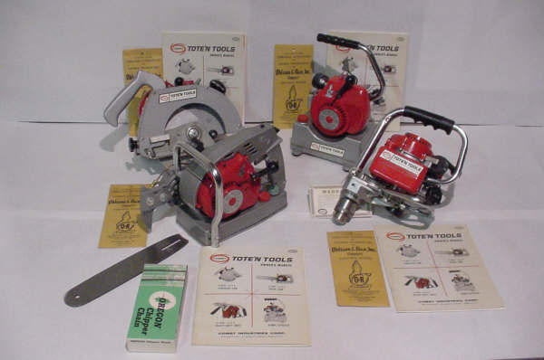
Joe posted a display pic of the 4 Comet Tote'N Tools a while back so I put mine together for a similar pic. The drill is the same but tagged as Drillgine instead of Tote'N Tools. I've been debating on whether or not to cut a coil cover to fit the chainsaw. Maybe when it's painted I'll decide.
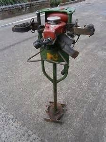
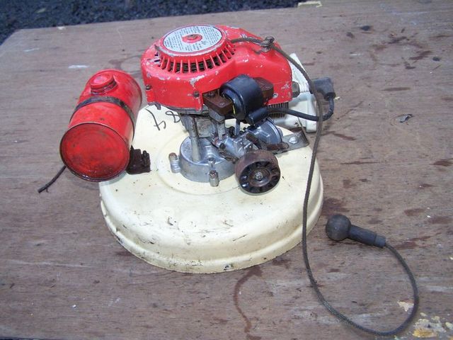
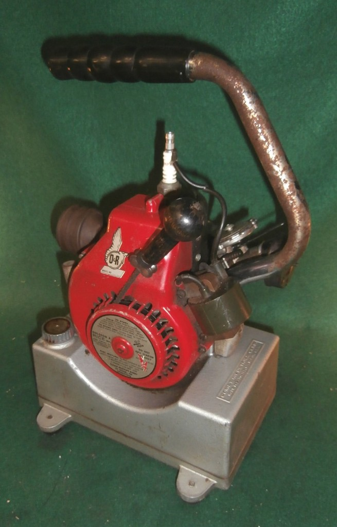
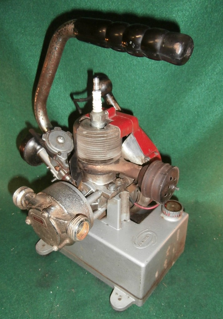
I acquired a Comet Pump at the Dublin NH engine show this weekend. It appears to be an early unit. It has the older style coil, a round governor rod, 10mm spark plug, a blued steel air deflector and a carb with a side mounted needle. The tank is painted with the same aluminum hammertone as the Comet saw. The attached pictures show it in the "as found" condition. Haven't even dusted it off yet.
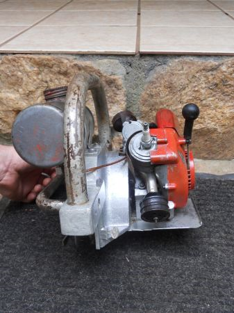
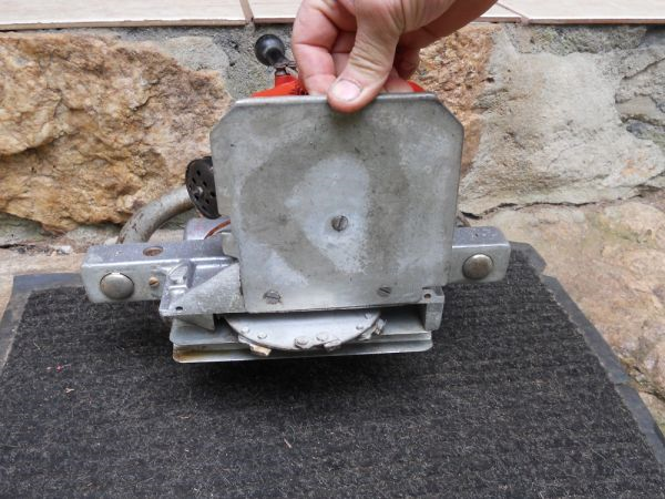
This strange saw uses a blade with teeth on it which are like a chainsaw. Cuts about a 3/4 inch size dado joint into lumber and is believed to be used for lumber framing. 2 passes will make a groove to fit a 2 x 4 standard US stud
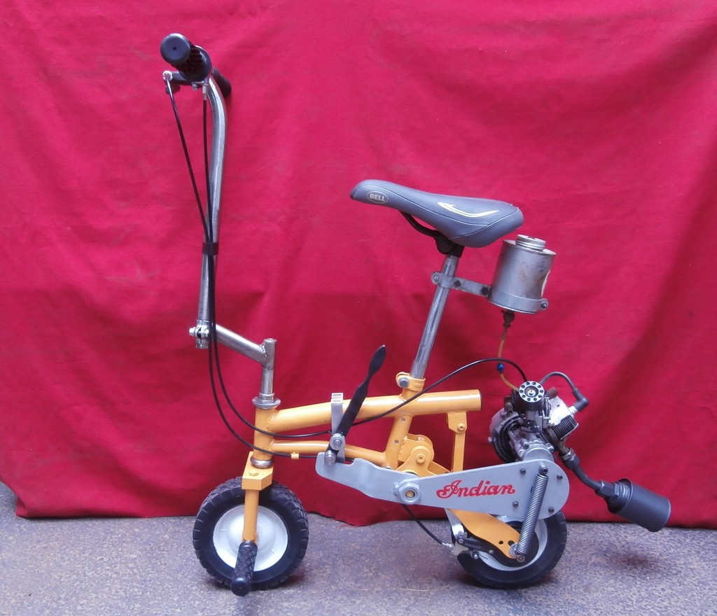
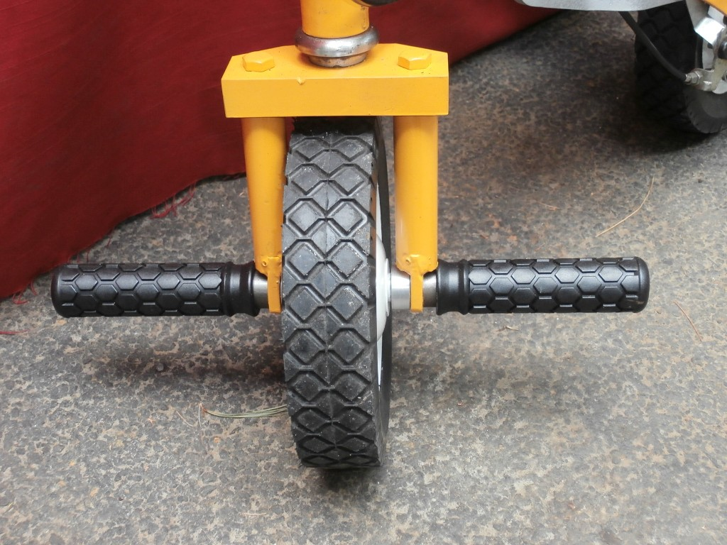
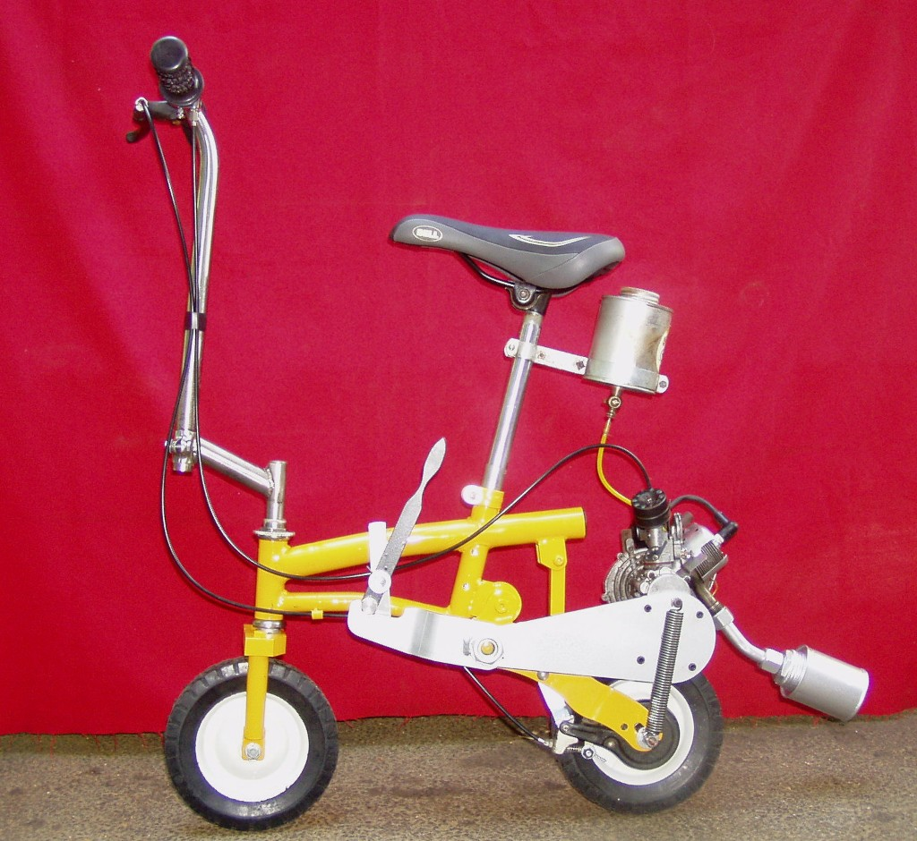
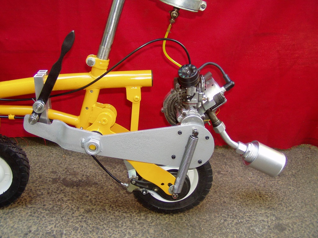
I finally finished the project. Got the foot pegs added and got the engine squared away. I rode it last night. It was a once in a lifetime experience. Believe me, once was enough for someone my age!! It is fast and the steering is quick.
At the Bernardston show last Memorial Day, a friend gave me a beat up mini bicycle. At the same show I bought an iffy Chickenpower engine for $50.00. Here they are today. For reference, the tires are 8" diameter. I figured that I would take pictures before the first test drive - just in case.









Chicken Power manual
in Ohlsson and Rice
Posted
Here's a manual. Comes as a folded booklet so some views are upside down an sideways but it can be printed and folded if you want one to go with your engine
ChickenPowermanual.pdf