Yes Norm, very handy and will have a fair bit of work for them on this.
Not made great progress, but have machine cut/threads on several short rods and finshed the 8 brass nuts from the 1inch A/F (25.4mm) Hex stubs which are shown in the very first image on this.
Threaded 1/2" BSF and single chamfer . These represent pre-war A/F (across flats) dimension of the 9/16' Whitworth fixings-
Starting on the copper beating now the cushion is filled with sand.
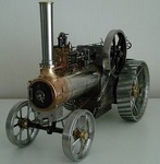
Trying to make progress while I have a reprieve from the dreaded R/Arthritis in the wrists. Just to give you an idea of this setup, here is a pic of the rough plan/layout of the working bits-
So left - right there is the water pump - speed reduction unit, then the engine. A 1954 Villiers Midget Mk2 98cc. Fully overhauled with a rebore +0.030" and new rings etc.
Being static, the engine will need additional cooling, which will require a cowling and cooling fan. The Mk3 Midget has this built in, but blows the air from the flywheel side.
I want it the other way, so have to make the shrouds , fan and drive etc.
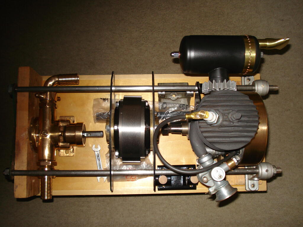
Keeping the sort of Victorian 'Jules Verne' style, I'm using copper sheet from an old hot water cylinder for the shrouds, riveting where necessary and maybe some embelishment?
The first pattern from my drawings marked out/cut from the sheet and began rolling to the diameter of 4.5 inches (114mm approx) -
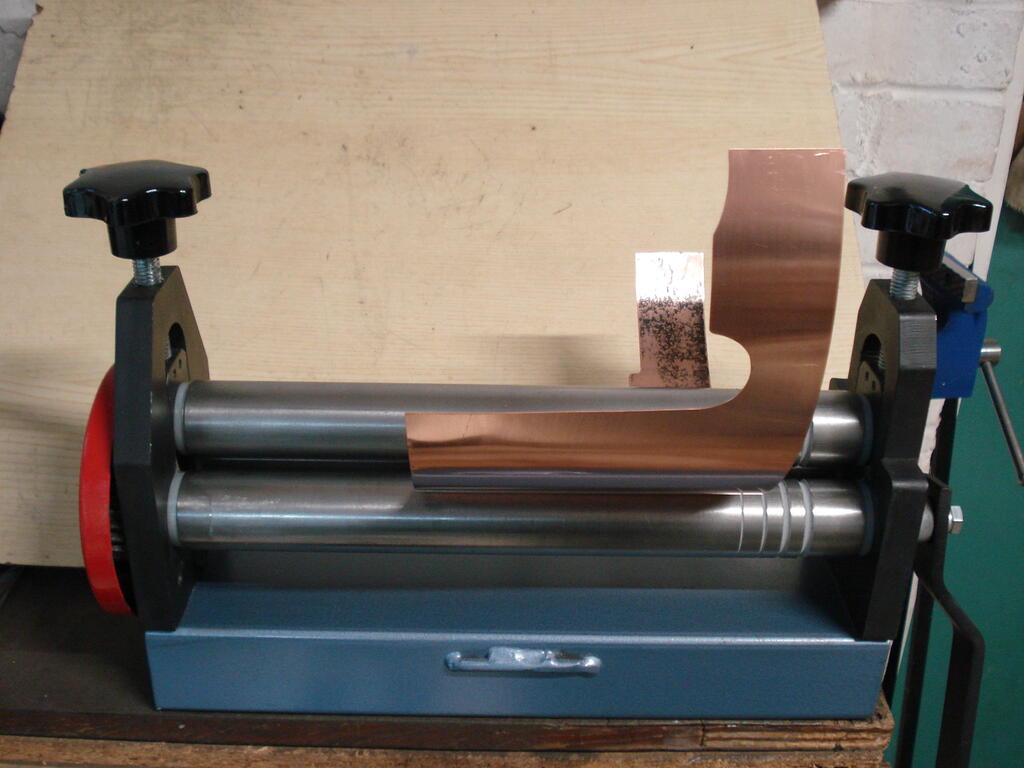
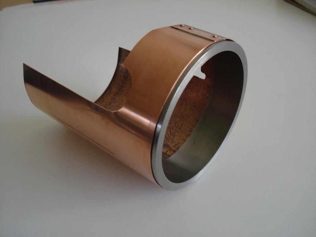
Fortunately, I have a piece of thick steel tube of the same diameter which allowed me to tightly form the intake area and rivet/solder the joint-
This is now ready for shaping (bossing) to fit the contours of the cylinder etc. A first time challenge for me.
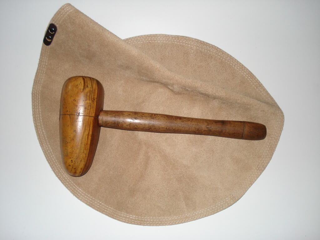
I obtained an old Lignum Vitae Bossing Hammer in need of some considerable attention, so I refurbished it back to good condition and purchased a large 15" dia H/duty leather cushion-
Will have several jobs for these tools on this project and the washed Silver Sand is currently being dried, ready for filling the cushion.....meanwhile-
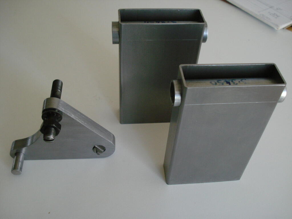
I had to redesign the engine mounting plates to position the engine inline so I can use direct couplings. I spent the last 3 days marking out, hacksawing and filing the 4 plates after drilling/reaming the holes.
Also made the reduction unit mounts ready for welding up, along with the engine ones at the same time-
With these parts all assembled in place, the shafts will line up and I can make the direct drive couplings with an allowance for any small misalignment, rather than use chains and sprockets etc.
Pitting or pips on the points faces indicate either over, or under capacitance. Depends which side of the circuit they are.
Check for any possible short to earth/ground point in the circuit. Is your Spark plug good?. Check for spark with the lead wire end.
Suggest you obtain a copy of a parts list for your specific Techy engine version.
Once you have the correct part numbers for the Coil, Points and Condenser, you can search places like this. -LINK- .
Maybe check the Tecumseh Manual listed in the 'Downloads' tab on the header line on Home page here for a start. if no good, search online for your engine version.
Provided the Magnets in the flywheel can attract a large screwdriver flat end from about 19mm away, it should be ok to produce a good spark.
Replace the points and condenser with new ones together.
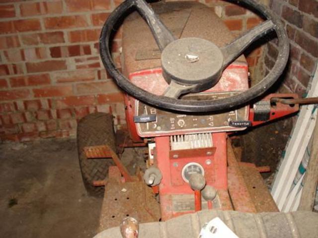
Tidy machine Norm!. Good find. The steering wheel is a WH Belgium Factory fit (made in Britain). Yours is missing the Centre Boss and had a chrome self adhesive WH decal in the centre.
I gave Roly the spare original S/Wheel & Boss from my C-120 project when I sold him the Tractor. I have a spare decal still if you can/want to find a centre Boss to fit that one.
My 72 Raider 12 when I first found it in 2008 shows the same S/wheel you have-
Drawn up engine mounting plate design and need to obtain steel sheet to make 4.
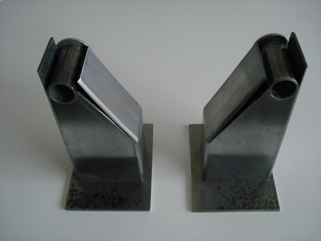
The 2 stanchions from 60 x 40 mild steel box are taking shape ready for welding up -
Had been searching for a genuine Villiers vintage exhaust, but realised they want too much money for not much style. I decided to make my own to suit the design I wanted
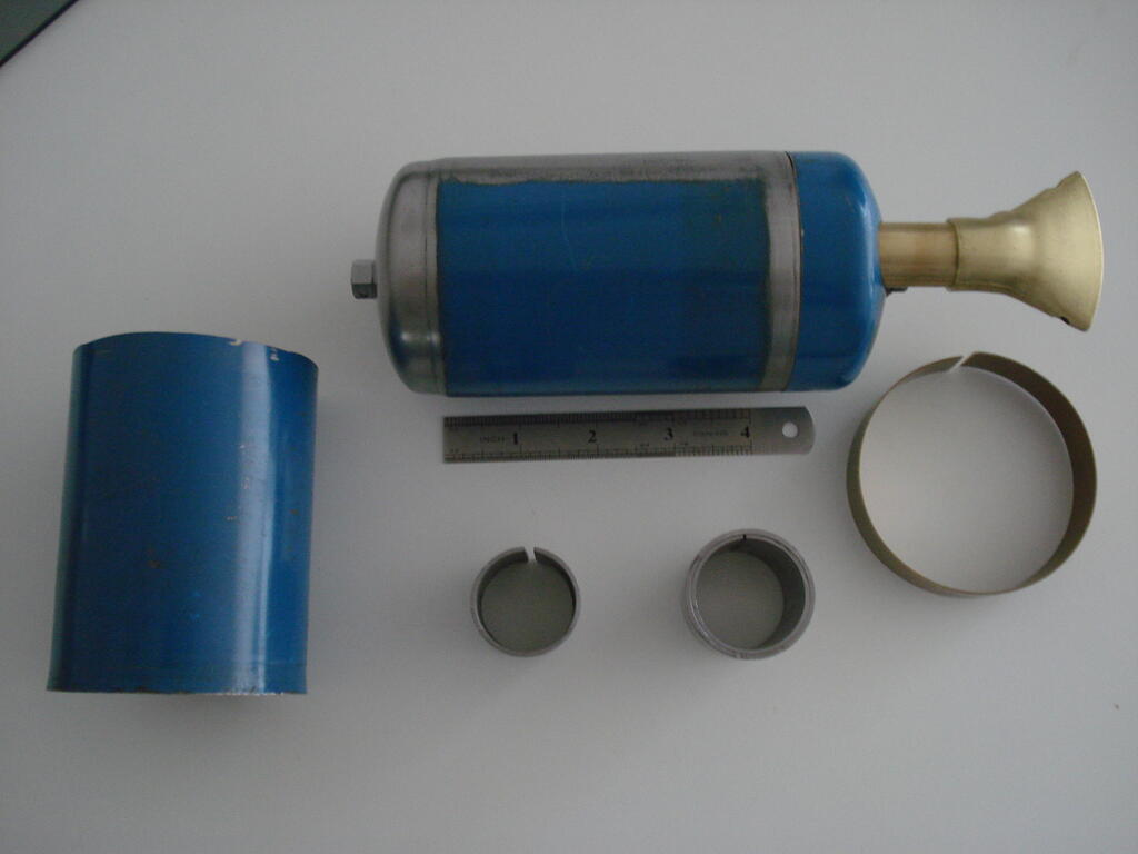
An empty disposable propane cylinder became the victim after getting the picture in my mind of how I want it. Constituent parts after much searching of materials, measuring, cutting & machining-
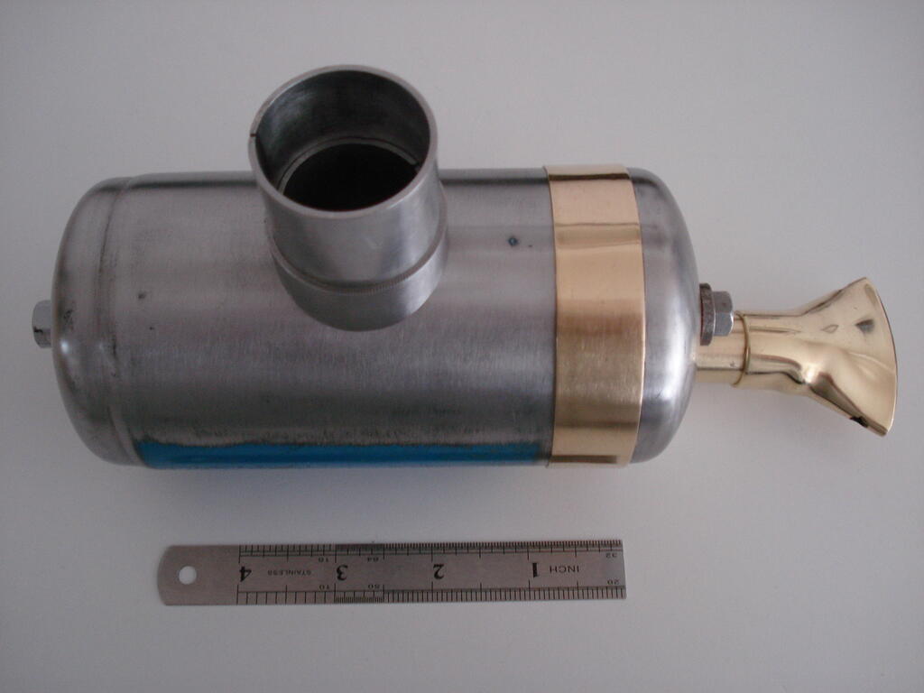
Ready to weld the 3 tubes for the outlet to the body and the test fit of the brass banding which seals and registers the butt joint end cap prior to riveting up-
The brass banding was cut from sheet, rolled and silver soldered the ends to form a close fitting ring.
The brass outlet pipe is from a 1954 mower front wooden roller insert, and the fishtail outlet is from a redundant 1960s Ronson Blow torch kit.
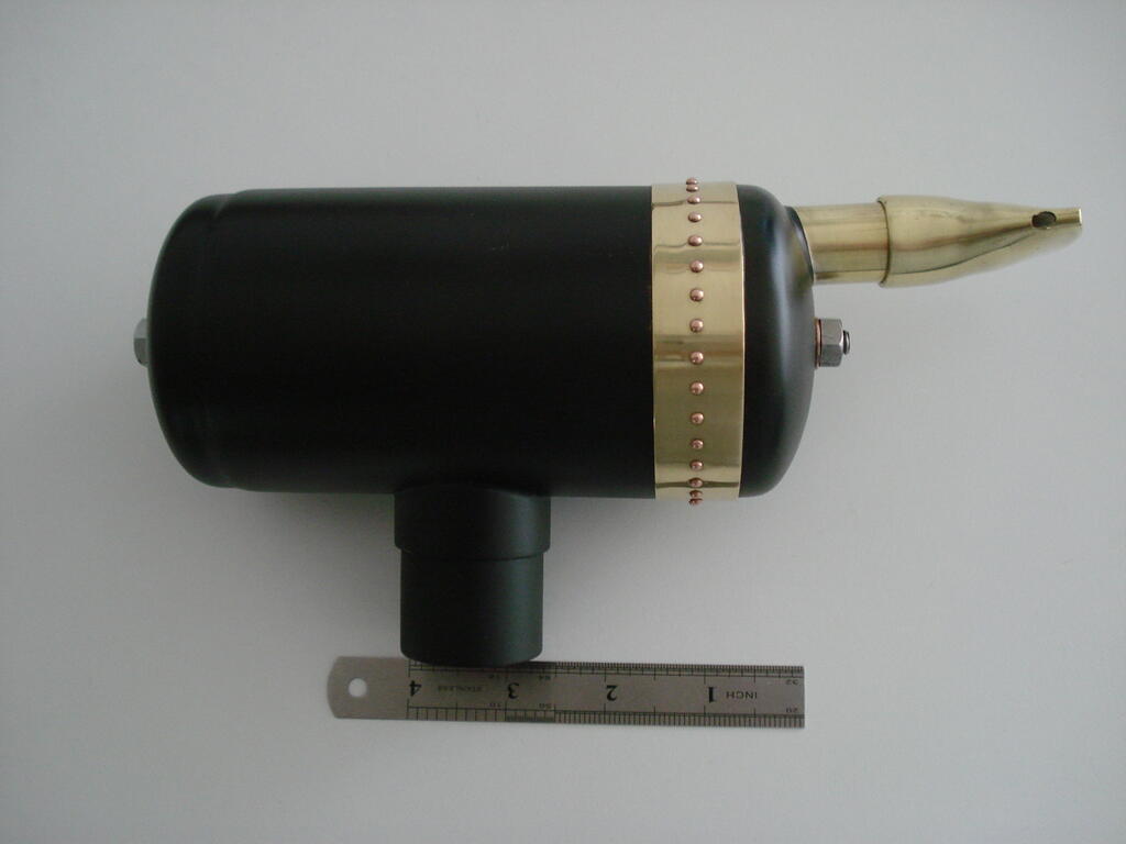
All finished and a coat of VHT paint cooked at Gas Mk6 for an hour-
I've got a finned exhaust clamp from a Triumph T120 which fits perfectly to fix it onto the engine.
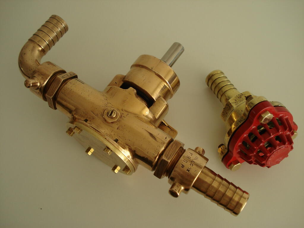
I finally decided that this project will be a 2 stroke powered Water Pump.
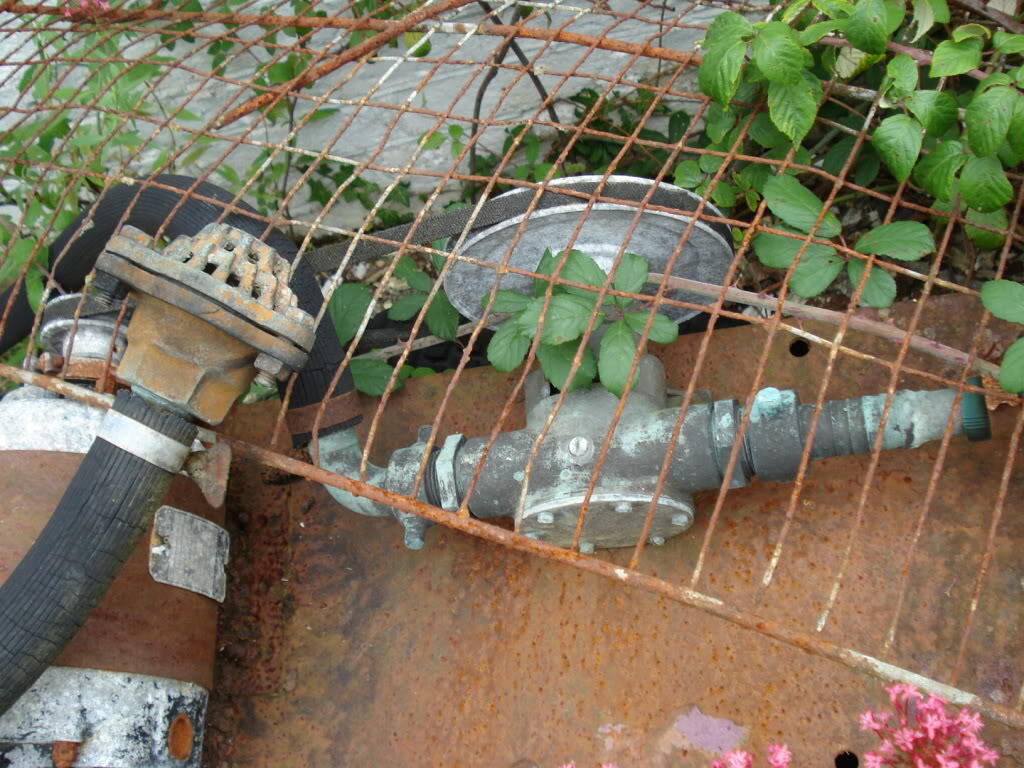
I rescued this old slurry pump with pickup strainer after laying derelict outside for 30 years-
I fully rebuilt this back to new internally and improved the appearance with a bit of cleaning etc. Early 1960s 1" BSP Jabsco model of considerable durability-
Still being manufactured and this version/size will set anyone back £250 + without fittings !.
Low running speed of about 500 rpm will shift 80 ltrs per min and can pump/self prime comfortably from 5 metres head of water.
All this pump work was done several years ago.
Not wanting to use belting for drive(s), my options are :- inline flexible coupling, chain drive, or combination of both.
Will be mounting this on a wheeled truck of some kind to tie in with the general style theme.
It's been a long time since I was able to spend time on this. Only now just starting to revisit the project. Plan to make this a priority and finish this year while I still can.
I've been putting details down on paper for it's design and progress, so hopefully will be posting updates soon.
Checked my stock, only have a good Inlet Valve left. Must've pased the exhaust one on?.
Another suggestion is to grind down an inlet to the exh spec. I presume you still have the old one?. Would need to be done by a good engineering shop person though!.
I sympathise with your resignation to part with these items. I also have had to change direction and stick to small, light stuff. I hope it all finds a good home .
Thanks for the pics Norm. Well laid out garden with interesting implements. Imagine a 'Forth Bridge Painting' regime to keep them all fresh looking like that.
Bumped his topic as I had to make more improvements to it's condition. Plus I need to excercise the hands caused by R/Arthritis, so glad to get back into the workshop.
The spindle/chuck mounting bodge of a cut off piece of bolt shown in earlier pics was just not good enough.
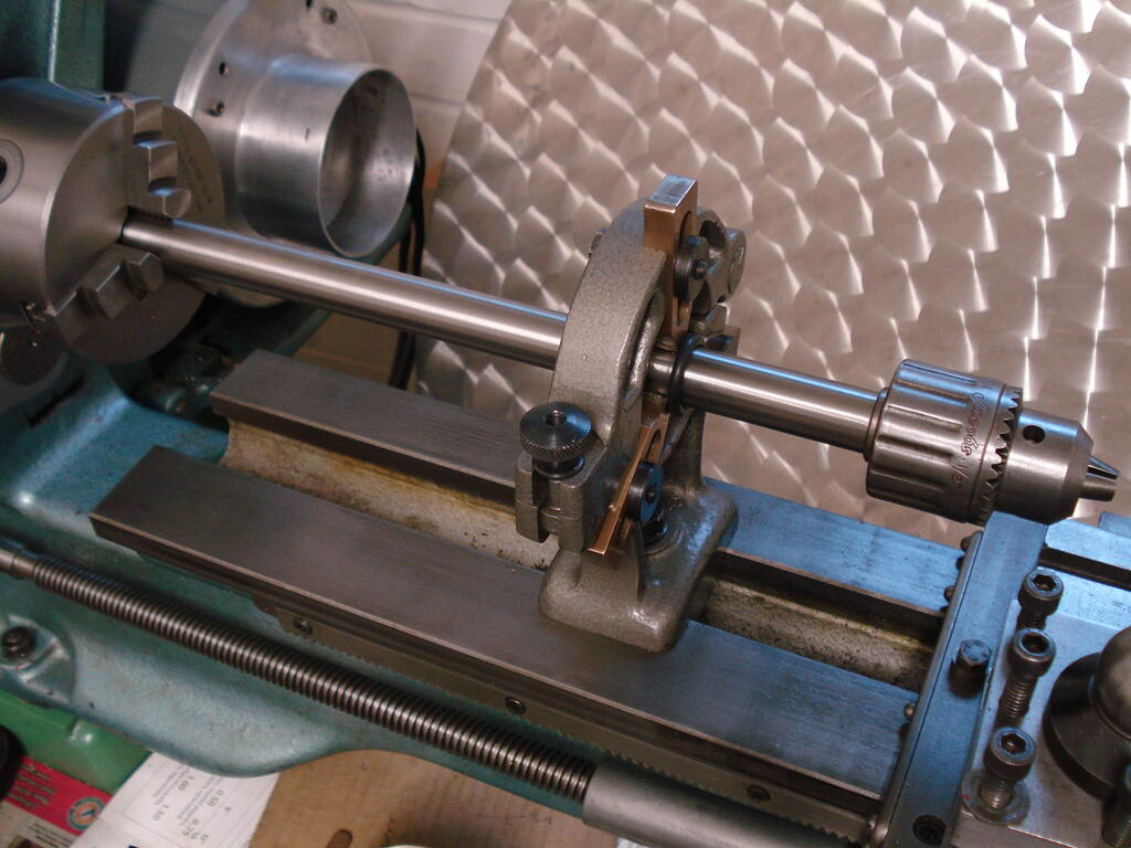
I made a new complete spindle from 3/4" (19.05mm) dia silver steel. Set up in the lathe and acurate to within 2 ten thousandths of an inch (0.00508mm) over it's length.
Pic below is after machining the chuck thread on the end-
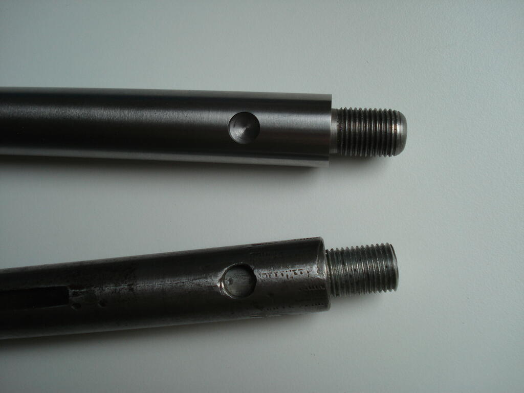
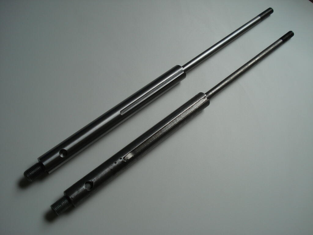
Comparision of the old and newly machined spindle ends-
After measuring, I found I could reduce the length of the 3/16" (4.75mm) wide cut slot for the new one, which produces a better bearing surface. the chuck thread for the English made Jacobs chuck is 1/2" x 20 tpi UNF, and the smaller diameter top end threaded 3/8" Whitworth. Both were screwcut on the lathe (my 1st attempt at power feed screwcutting)-
Did a check with a 5/16" (7.95mm) diameter long Dowel Pin fitted in the chuck while still on the lathe and it had only 0.0015" (0.038mm) runout at 1.5 inches (38mm) from the chuck jaws!, so pretty good allowing for the age of the chuck.
Did the same after fitting back into the drill and adjusting lower bearing clearance, I got 0.003" deflection while applying a side load, so I am more than happy now with it's condition.
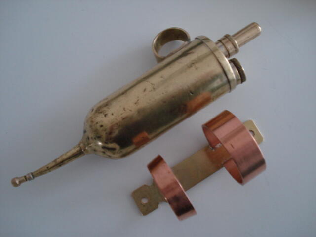
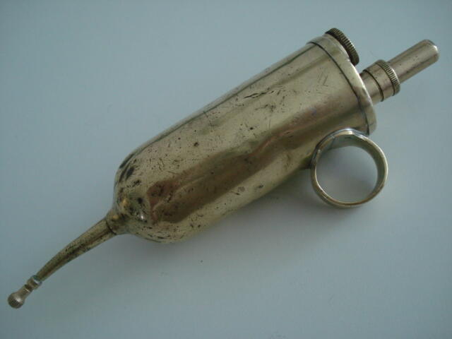
Thought I'd add another find to this old Topic. Acquired another pressure feed 'Oiler' for a 'Fiver' (uk£5.) It was amongst a box of bits from a shed clearance. It was in a bit of mess, seized and badly beaten-
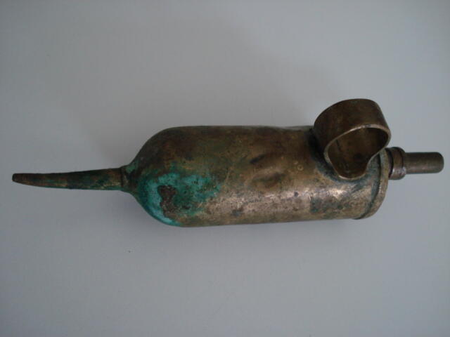
Initial clean up to see what I had revealed it was another Lucas Oiler from the 1920s. Diameter is 1. 1/2" (38mm) to give you an idea of size. All I could do was bite the bullet and desolder it all and reduce to constituant parts and see if I could clean it out and repair it back to working order. After a few days work, I had reduced it to this-
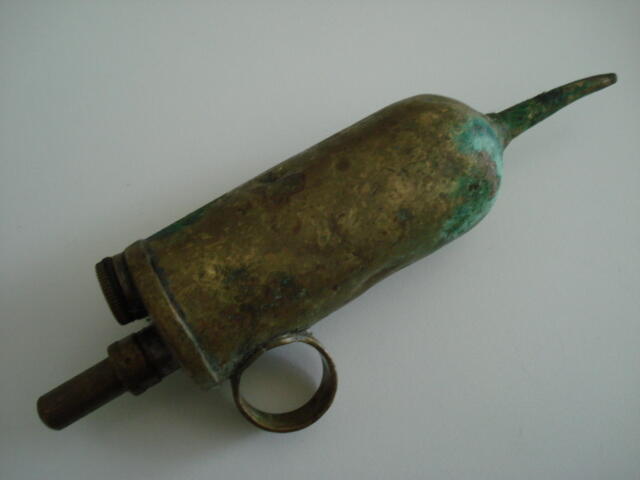
I managed to remove some serious dents to improve appearance, but will always have the scars of use/misuse to show it's age.
I had to overcome a problem with reassembly due to not being able to solder some internal joints and ensure they held in the right place and soldered/sealed together.
So I hard soldered some parts and so able to ensure it all went ok when 'Closing up' the 5 other soft soldered parts/joints all at the same time .
The bronze 3/8" dia ball is a replacement, as the original steel one looked more like a large lump of weld spatter. So I lapped the new one to it's seat for a good non-return seal.
New leather washers made for the plunger and filler-
As usual, the end cap and threaded section was missing, so I reproduced a nozzle and cap. The cap having a leather pad in it to seal it when screwed on.
After several flushes with acid, soapy water and dried out, it had the plunger sealing washer greased, piston oiled/primed and filled.
No leaks and can now deliver a single drop or stream under pressure at any angle. The fine nozzle can displace the small ball in oil nipples to lubricate, rather than have a cumbersome Grease gun type nozzle which is useless in confined places on machines.
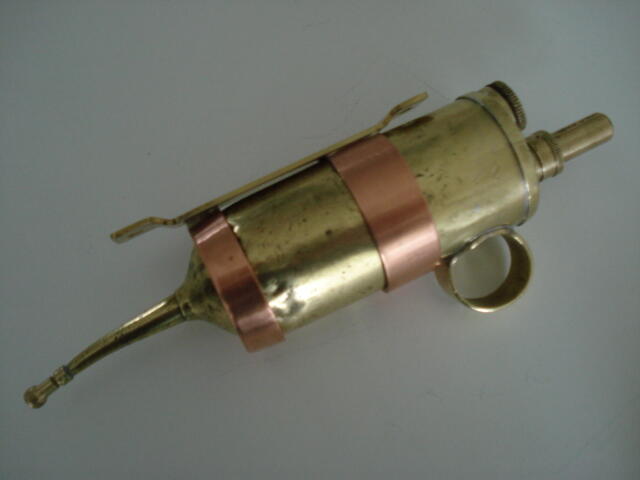
So that's the Lucas Oiler No 36 given a new life and will have a copper 'Holster' to safely stow it on the Lathe or Mill in the workshop.
Can't ID it positively. It could have been imported. Monro Ltd imported/distrubuted SIMAR cultivator units from Switzerland initially, and then produced their own version of a Cultivator late 40s/early 50s.
Suggest you check the thread form on a bolt/nut to see it is Metric, Imperial or Unified (U.S) and may give you a clue. Not sure if they produced their own Seeders, but looks way 'over engineered' for post war UK to me, compared to other models I've seen.
Look's like it had a lid on the hopper initially due to the unfaded paint line on the front. Are you giving it the full treatment?.
Thanks for checking anyway Ray. I'll send a PM to Chris (Showman) in the hope he sees it. Last resort is to get Roly to buy 'States side'. At the moment, he robbed 3 from his C-141 to cut the grass!.
Yeah, thanks Norm. I thought about it, but didn't want to impose on his reajustment to normality. Don't think he comes on here very often nowadays?. I'll give it a few days and send a PM. Regards.
As a result of a panic email from Roly who bought my C-120 back in 2018, he is desperate for these bolts. He needs 3-5 if anyone in UK has spares to part with?.
Failed large in the Annual Service checks/requirements 3 years running and has just noticed he's lost 3 bolts !!!.....and nearly a wheel. Any help will be most gratefully received in directing him to a UK source of spares.
Well done Nigel. An awesome building/workshop to turn out your awesome projects in . As for condensation, looks like there is still a lot of moisture to remove before it's fully dry at this time of year.


") . Still , it will keep you occupied getting it the way you want it.
. Still , it will keep you occupied getting it the way you want it.
 .
.
Bits for my next Project
in Metal Shop
Posted
Yes Norm, very handy and will have a fair bit of work for them on this.
Not made great progress, but have machine cut/threads on several short rods and finshed the 8 brass nuts from the 1inch A/F (25.4mm) Hex stubs which are shown in the very first image on this.
Threaded 1/2" BSF and single chamfer . These represent pre-war A/F (across flats) dimension of the 9/16' Whitworth fixings-
Starting on the copper beating now the cushion is filled with sand.
Regards