Sorry to hear you're having problems Alain. Would be sorry to see you go and your absence would leave a large void here.
Persevere and try Karl's advice. Don't ever let any IT gremlins grind you down. I've just beaten Ford UK into submission with their website after a frustrating 3 weeks (punch air).........
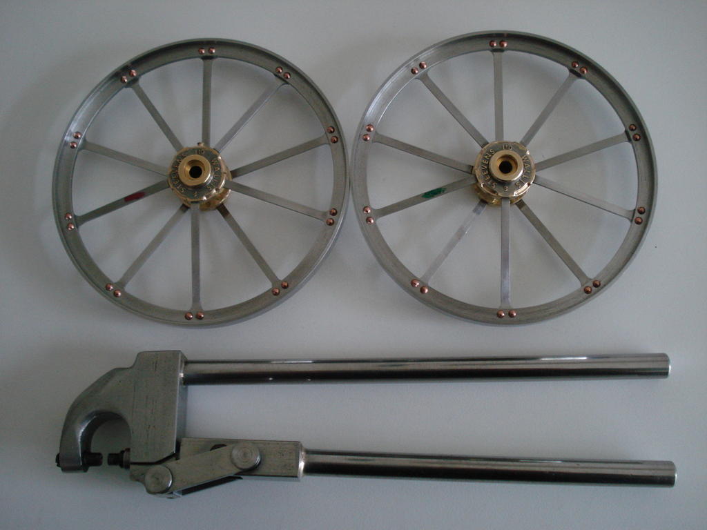
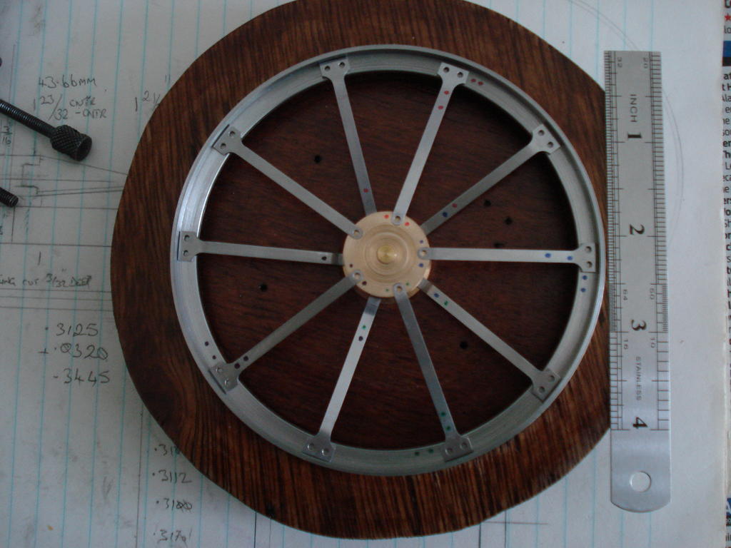
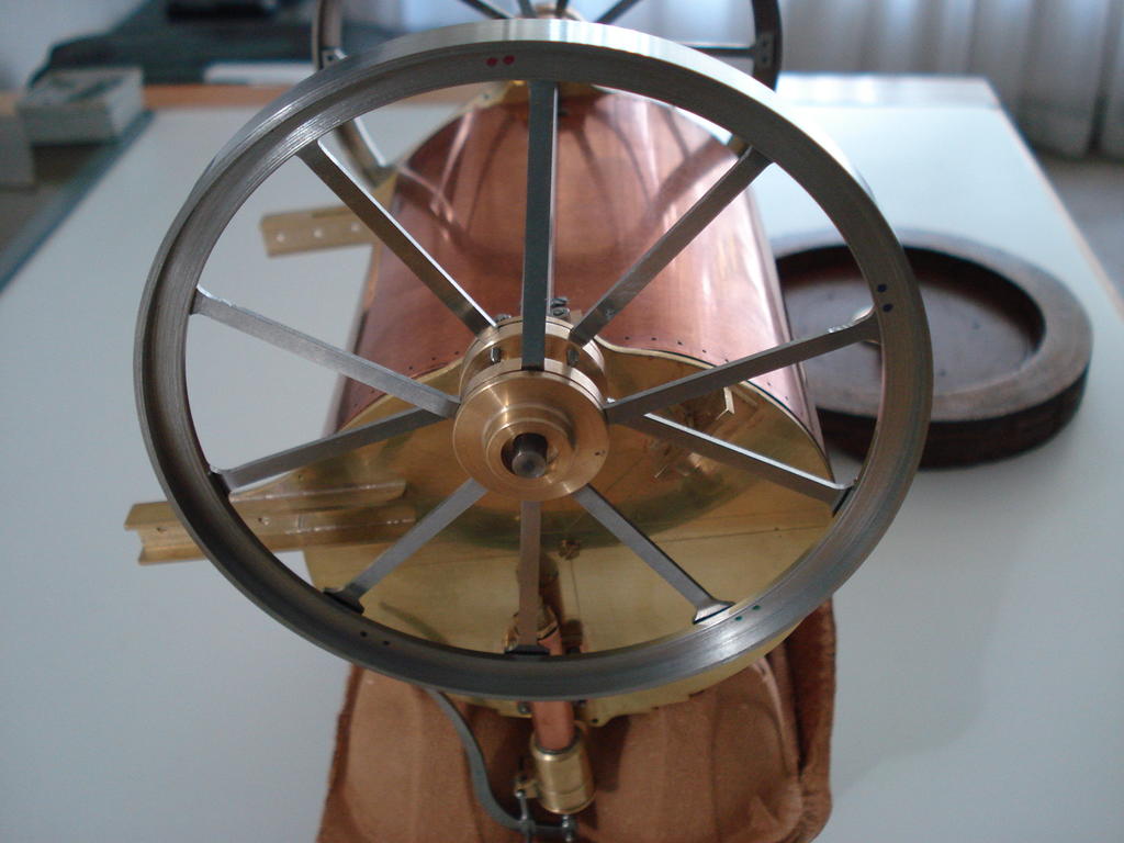
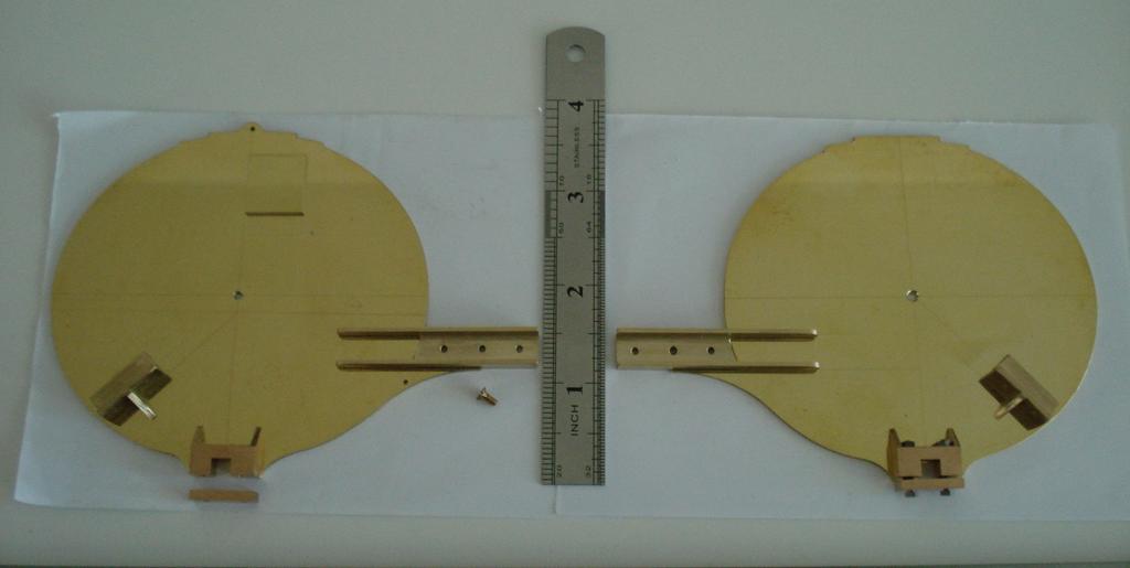
Forgot how so very complicated it is to build wheels in this manner. Last lot were 35 years ago!. Happy with progress though.
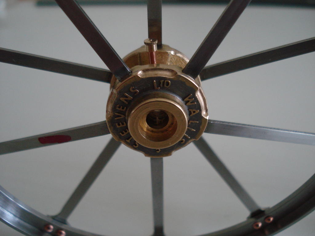
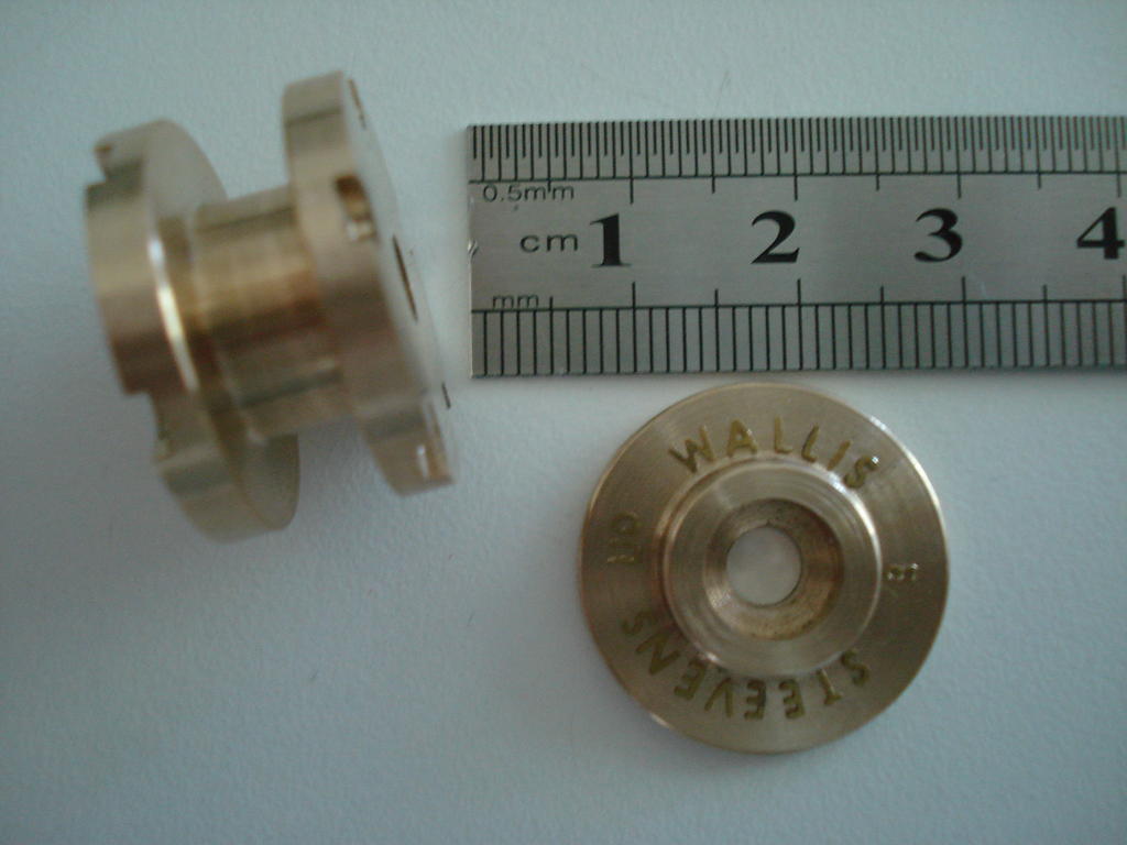
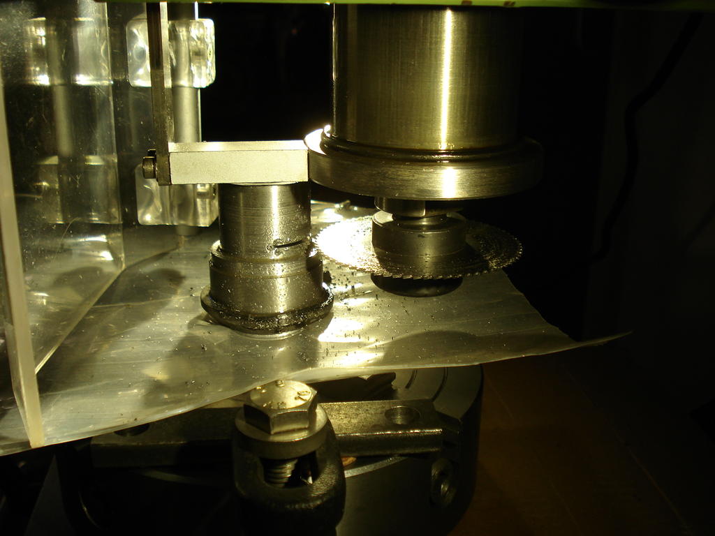
With the spokes secured in the hubs in the right places, the covers were soldered in place first, then I began meticulously setting each brass letter in place around the Hubs
to replicate the 'Cast In' lettering. I had planned it out way back when I first made the hub parts-
I used a dirty steel washer to hold the letters in place and bolting it all up to keep the hub parts lined up while I 'cooked' it to sweat the letters into a thin bed of solder.
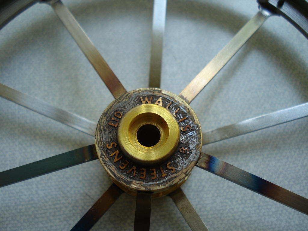
After removing the retaining bolt/washer-
After an initial clean up and bonding check-
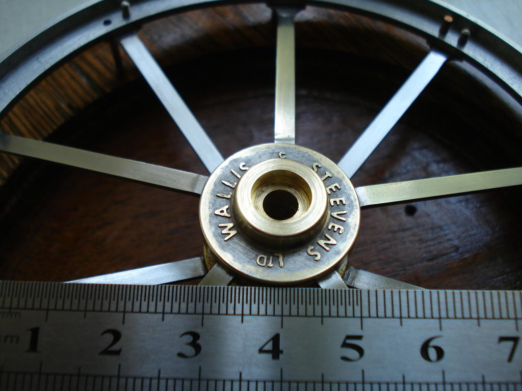
Still more machining to do before finally riveting them up
Hi Ian , Shame you're having to downsize and localise your operation. It's hard having to deal with these kinds of serious blows.
As mentioned when we last met up, I know exactly what you and and especially your wife have gone through.
I've been doing the same with machines and W/Horses where I only play with small light work now and enjoy the space I now have, but I had a choice, where you perhaps have not.
Chin up and just tick over within your limits. Best wishes for you both.
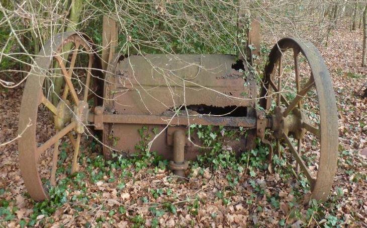
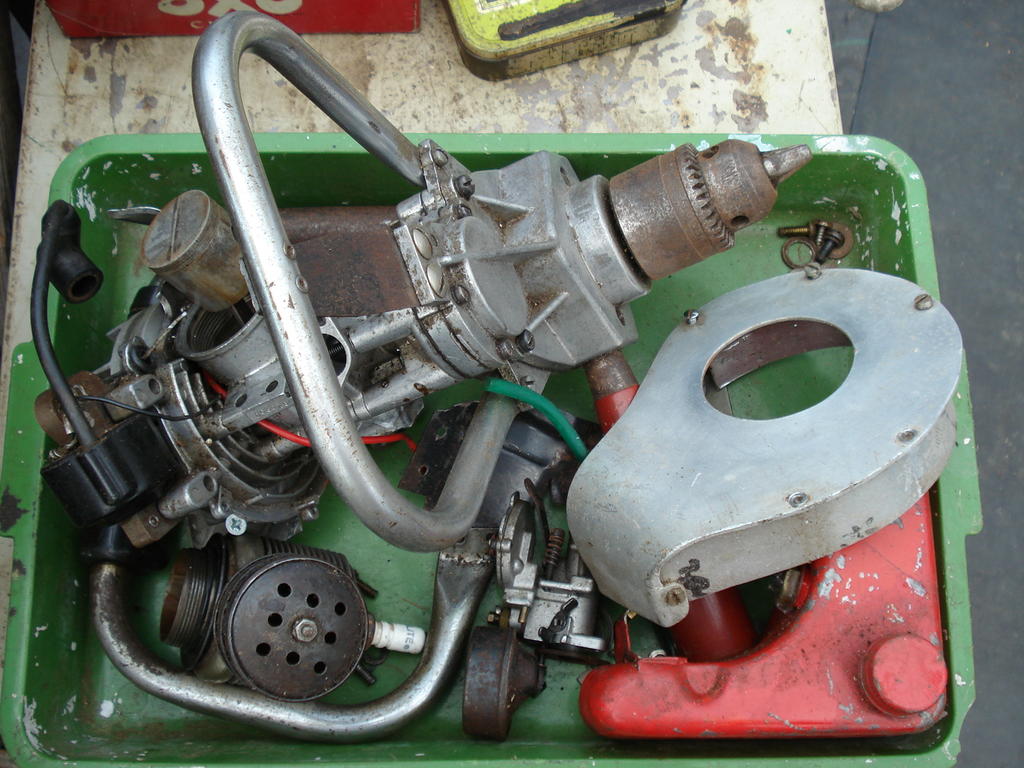
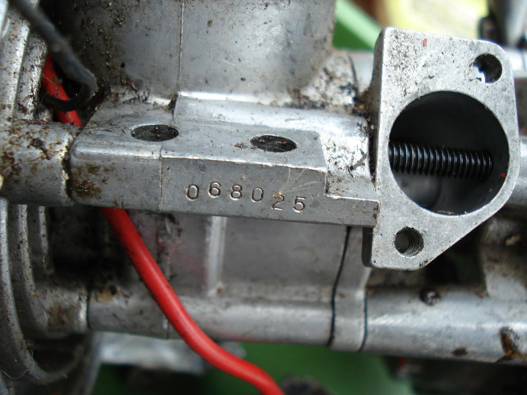
I know there is a lot experience and knowledge of these O&R enigne powered machine on here, so I thought I'd dip a toe in the water and post this sorry sight in a Tray-
From a quick scan of the topics on here, I presume the red paint indicates an early-ish model.
The engine cowling is a devoted effort by someone in the past to repair or keep running this unit without replacement parts being available, as the retractable pullstart is long gone.
Being offered it, I'm tempted to have a go at it, but doubt if I could get it back to original appearance, the cost and availablility of parts and the current condition.
The only numbers I could see on the motor are shown here-
This being in the UK will not be so easy to sort, so may put under the bench for some 'over winter' repair therapy?.
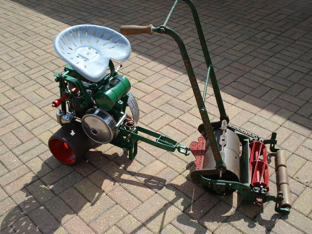
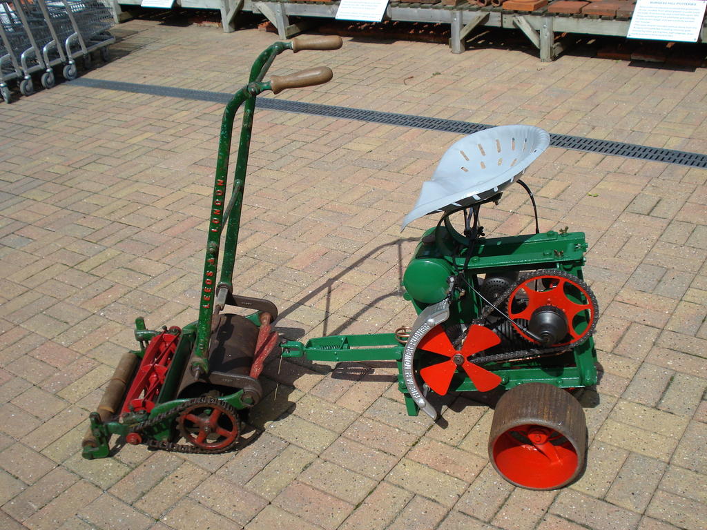
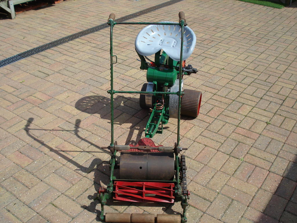
Will come back with an update on this towards the winter. It has now been married up to a good example of the original mower it used to push around in the 1920s-
Needless to say in the meantime, it's being parked up on a display stand to earn it's keep at the Museum. I'm busy with miniature stuff at the moment.
There are several possible reasons for excessive oil consumption in these older 'K' engines, so I'm not sure if you have covered all of them off yet?.
Use of correct Oil. It is often experienced that use of modern synthetic blends etc in these engines can cause high consumption. They were designed for Mineral based Oils.
A good 30 wt oil of spec as specified in the manual for air cooled, splash lubrication will always serve well.
It is also possible that fitting new rings to a worn/used bore will not improve it's current condition very much. It may be worn 'out of round' , of which there is a limit quoted.
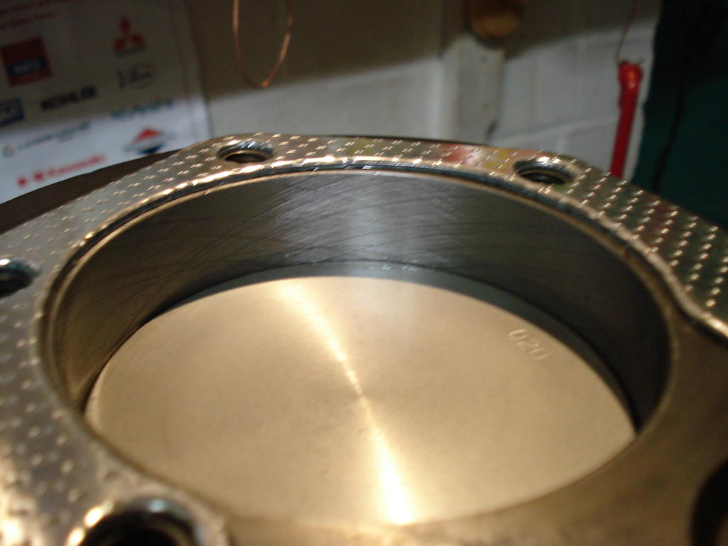
As mentioned, deglazing a cylinder can work wonders for a tired engine, but it needs to be done correctly to resemble the finish of a newly honed engine.
Kohler recommend the honing marks should intersect at approx 30degrees, and if these marks are either too steep or shallow, the oil consumption/friction can increase.
Here is an example of the correct honing finish (after a rebore)-
There is another area to check, if not already done so.
The valve guides are a possible cause and can have the same affect as worn rings on Oil use and by causing the crankcase to be pressurised, instead of running
with a partial vacuum.
These are good engines and are readily able to be rebuilt, so I for one am pleased with your clear determination to get this one back up to spec.
I hope your potential engine rebore service is local to you.
It's a few years since I had a K301 fully worked by Sutton Rebore Services and I was so impressed by their standards and prices.
The sound of an almost 'back to new' engine running as it should is payment enough.
Your engine is listed as S12D. I used this to search and find ring sets for that model (12hp, points ignition).
There is also a TRA12D, identical, but with electronic ignition, but I suspect they both use the same ring part number.
You will have to obtain a service/parts manual to double check what you need, or provide a retailer with all of your engine's model/spec and serial numbers.
Wisconsin are still in business in the U.S and suspect will be the only place you will get replacements that you can trust and be prepared to pay premium prices/delivery and import charges.......then again, it depends where in the world you are located???
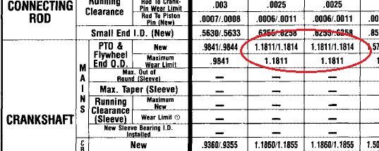
Thanks, i've posted it on Redsquare. I did find someone selling replacements on the auction site and they were listed as 6206c3 bearings but this is metric and both me and my dad thought they would be imperial.
Ok, Thats me being a bit slow responding and you being on the same frequency!. Yeah, strange how the occasional metric dimension crops up in U.S. equipment.
The specs in the Kohler Manual for the Crank journals each end are not round imperial fractions in Thous of an inch-
They look handy, Richard. Where did you get them from?
Hi Norm, Yes, they should do for me.
Not best quality, or hardened/ground rolls, as they were painted and I had to clean it off them to ensure the rolls were smooth enough for the finer metals I will be using.
Took a flyer and ordered off ebay. Came from Poland. Bit anxious for the last week, as overdue and no update or shipping info since 20th June. All sorted .
Just waiting for some tooling for the Mill to arrive and I'll be bending metal at the weekend.
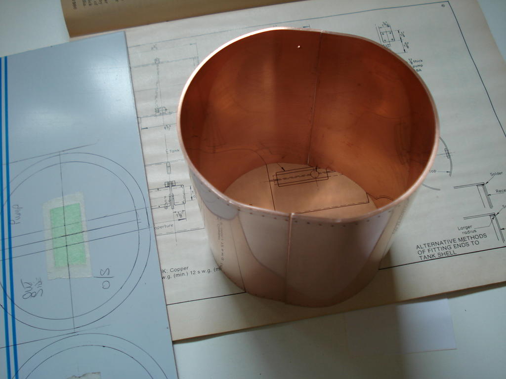
For many years, I've wanted to be able to roll sheet metal (in small sizes).
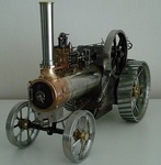
From shaping the nickel silver cleading on my traction engine to making fuel tanks and small exhaust mufflers.
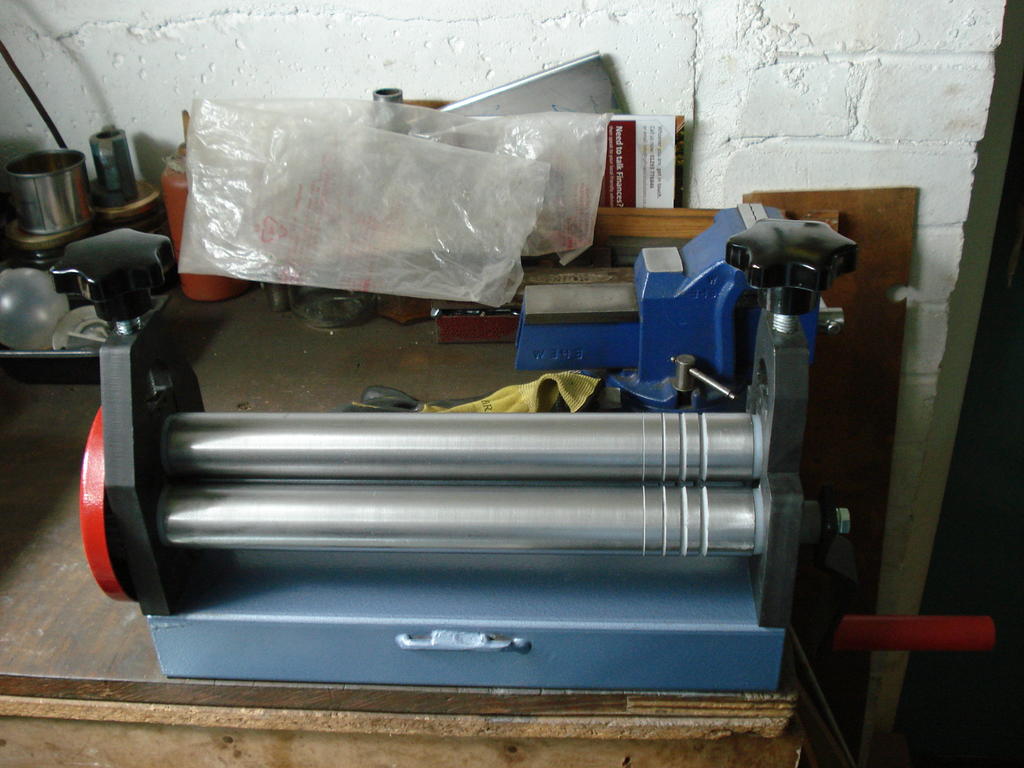
So after saving up the Workshop pocket money, I've finally got a set of Mini Bending Rolls-
Quite heavy duty rollers for a 300mm wide unit and steel geared. Plenty big enough for all the jobs I have for it, and at 14kgs, just unbolts from the bench to be stored
out of the way. ....I'll get around to making some Swaging Rolls one day
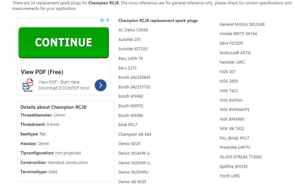
Manual reccommends Champion RCJ8 0.025" gap (unless running on propane etc). Not sure if modern ones are as good as the old ones, so here is a cross reference for loads of alternatives
Don't usually like to revisit old Topics, but this Tap came back to haunt me.
I started dripping fuel out of the Tap and apparently emptied the fuel out on the floor probably over last winter.
Having concerns that my workmanship, or the materials I had used were at fault, I took it back to find the cause.
Glad to say the bits I did were not faulty, but found the fuel was leaking out of the lever end.
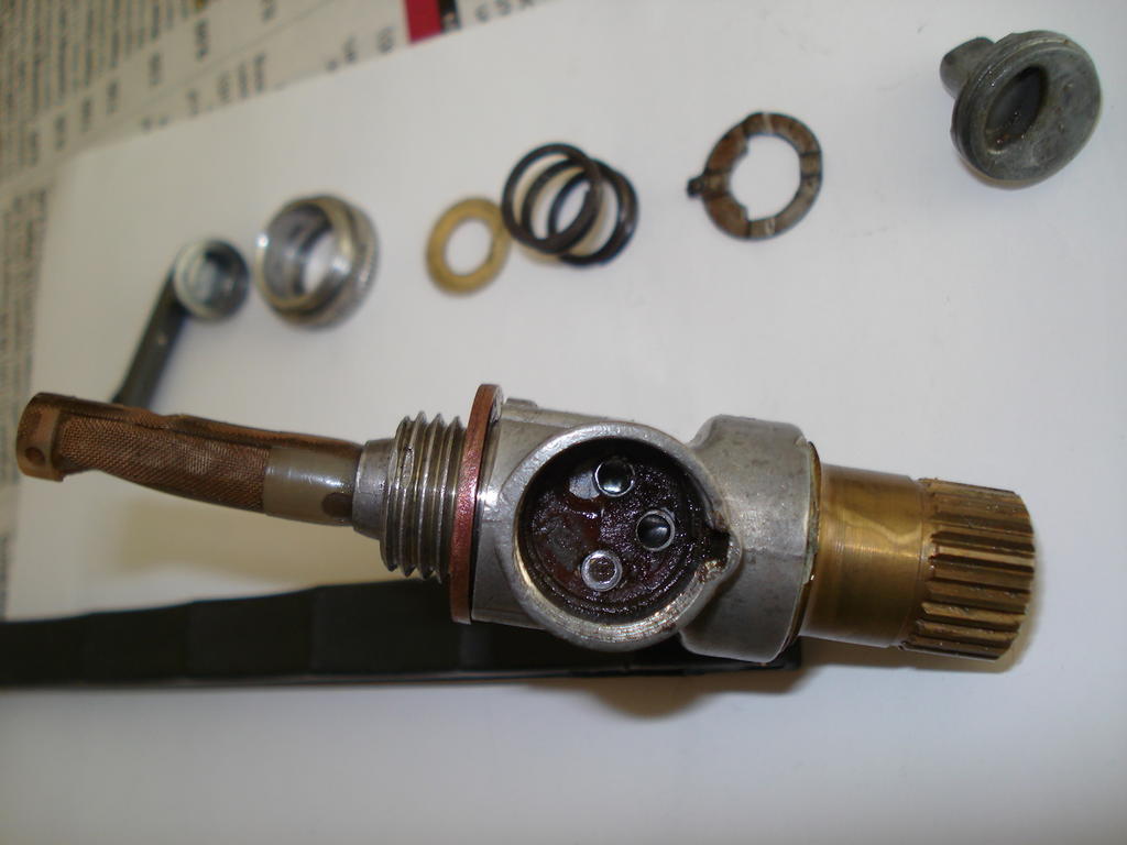
So I stripped it down on the understanding that if I can't fix it, they will have to replace the whole unit (if they can find one).
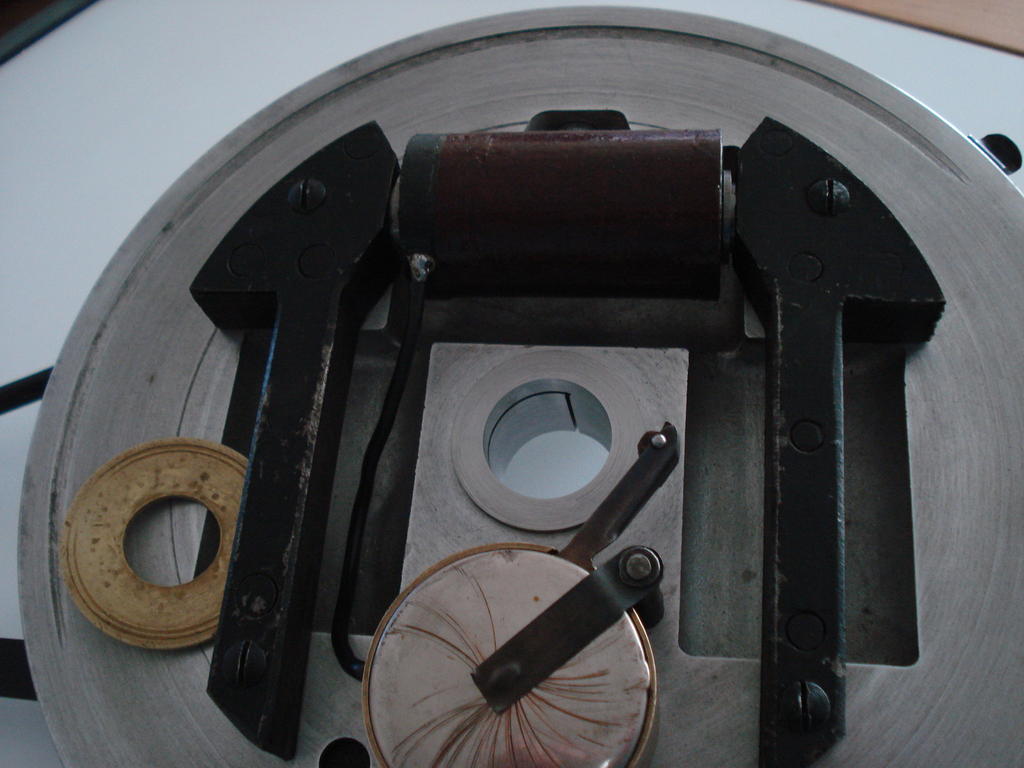
Talk about over engineered!. Seven separate parts just for the tap lever control !, including a plastic type seal which had dissolved/rotted which was causing the leak-
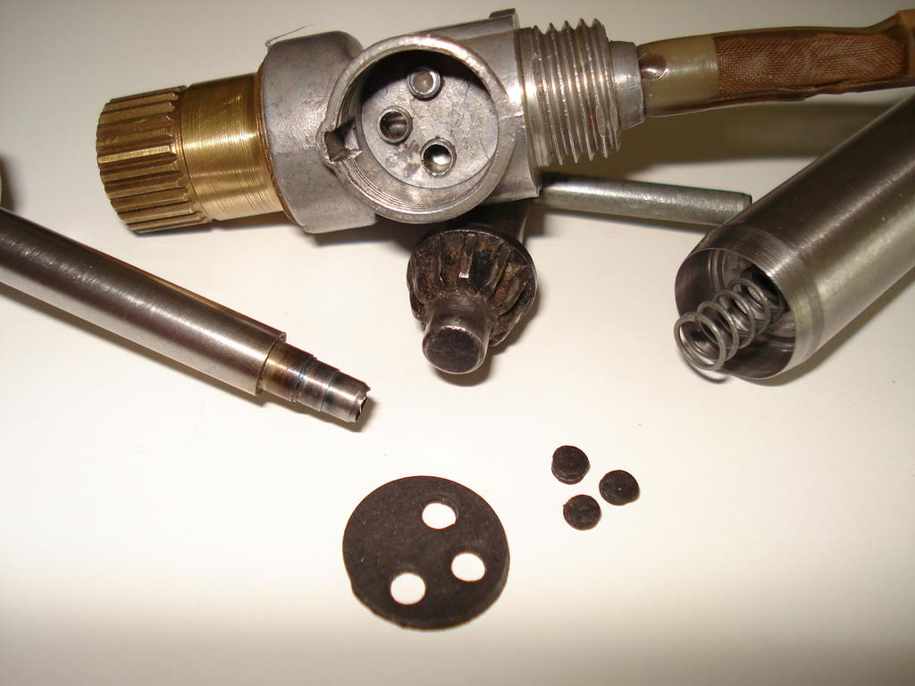
So as usual, I hit the challenge and went for making a replacement seal from fuel resistant 1.5mm thick nitrile/nylon reinforced rubber.
I had to make 2 special punches that could cleanly punch through the tough layers and in the correct positions-
Glad to say that when the cleaned parts were assembled and the tap fitted , there were no further leaks. Hope I've seen the back of this one now.
No real update yet and haven't had a chance to concentrate on test running this, but have primed the Carb float bowl to test the float valve which I 'Lapped' to ensure a good fit/seal.
Left it for a week to see how it fares. I suppose I really want to cover all the points that will make it work before fueling it up.
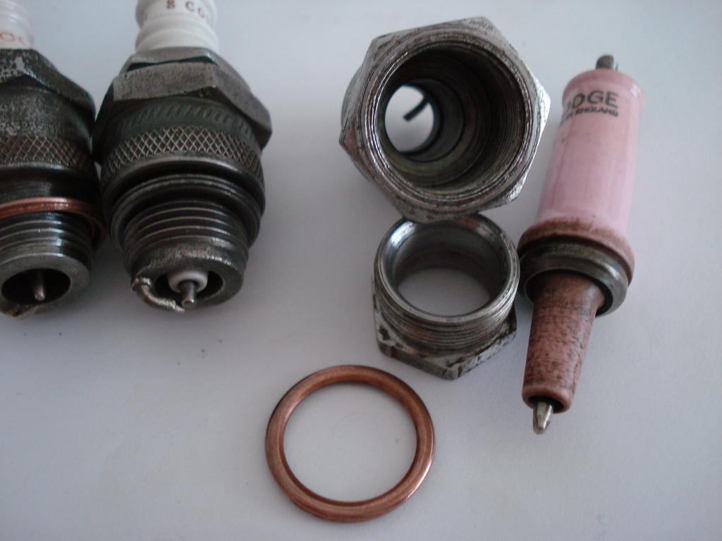
In the meantime, I wanted to give the Spark Plug stock a good going over.
I have the original 8 COM in the engine currently, but don't really want to rely on it. So I have 2 other 8 COMs and a Lodge BBL.
These I've stripped out and cleaned, as they all can be dismantled for cleaning. Did the Champions first, one is 1930s (left) and the other is 1950s.
The 50s one cleaned up best, but turned out to be dead. No continuity in the central electrode. The 30s one is perfect, 0.5 ohms resistance top to tip-
Had doubts about the Lodge BBL, but after sorting the loose body electrode, it cleaned up ok-
Has a reading of just 2.8 Ohms, so also good. This one is on the higher temperature side of the 'Warm' range that 8 Com is in and is good for Oily running engines.
Also have a good Vintage Lodge CV and hope to be able to test them all out on it, but I have to make 2 different threaded (Thumb Nuts) for them.
2 early ones are threaded UNC and the CV is 2BA !. Hope to update soon.
hi i have recently purchased a lloyds auto scythe and wondered if any one would have any info on a lloyds auto scythe please . or any brochures ect , many thanks alec hooper
Hi Alec,
Do you still need this info?. I may able to help, but not this week.
I decided to temporary fit the head just to keep things together, till I get the parts I need. That is when I found another PO's bodge. One of the head bolt holes by the exhaust valve, has been tapped out the 3/8th UNC. Plus the bolt used is slightly longer with a longer shank. Not much I can do about the hole, but the bolt I will cut down to the length of the others and run a die down the shank, to get the same amount of thread.
Good work on the head Norm, slightly higher Comp Ratio .
An early 70s style head with the plug hole central. Later version around 1974 was a heavier casting and the hole over the exhaust valve.
The bolt that nearly (or does) break into the exhaust chamber is a pain on these. If a head bolt is going to shear when initially undoing, bets are on it will be that one.
Can't remember if it's number 7 or 8 in the sequence, but was glad I put a Stud in there in my last one so it only ever needs the nut undoing without disturbing the stud.
A great thread and wonderful workmanship . Ignition - unless I’ve missed it, there’s no mention of the condenser, has it been changed? Judging from the number of faulty / weak condensers that I change on not quite so old engines, it may be worth a punt.
Thanks, and yes I did briefly mention the condenser situation in post #14 on page one.
I agree with you on the later canister (m1750 type) versions regarding their reliability/inconsistency. If this engine had that style, I would have replaced it irrespectively..
I don't have a pic of the back of the brass condenser/points box, but it is solidly filled.
The condenser, being the original patented design of 1921 is constructed using Mica sheets in between the aluminium plates (according to the 2 Authors of the books I have).
On this version, the whole unit is fitted into the box and then flooded with molten bitumen, so it's hermetically sealed within.
Modern Villiers condensers (mid 30s onwards-ish) were constructed using waxed paper as an interleaved insulator and these have a tendency to break down quicker (as per the books).
I decided to give the original one the opportunity to prove itself in it's quality/reliability based on the condition of the original points faces (platinum), where there was only the slightest sign of 'arc pitting' (coil/condenser side) and tiny peak on the earth/ground side, which could indicate a possible slight over capacitance when it was last running.
There are statements in the books that say these old versions rarely fail . I'll know where to look if a problem shows up.
The progressive condition of the spark was consistent using several spark plugs (non resistor).
So with a few backups, I'm going to run it initially on the original plug (Champion 8 com).
The worn Points Heel was likely to be a possible problem, but on assembly, the clearance/lift was way more than enough to set the points gap .
On 6/5/2019 at 10:58 PM, Stormin said:
Well done Richard. It'll soon be purring like a kitten. As near as a two stroke sounds to a kitten anyway.
Thanks Norm. For the few revs it's done so far, it seems to have a bit of a 'bark' to the exhaust note.
I'm expecting this to run at around 1500-1750 rpm, so a sound like the old vintage Bikes of the age and a bit noisier .
I'm sure if you can't find a set of wheels, carriage or cart, a man of your capabilities can make some.
A bit more than I could deal with without finding more large tooling like bending rolls and a larger welder Norm. A long search for the correct size may be the only way.
I reckon sorting the mower will be quicker.
On 5/10/2019 at 8:26 PM, Alan said:
Very nice Richard. Now we know what you have keeping secret all this time.
Not sure if it was worth the wait for people, but hope it is seen for what it's worth.
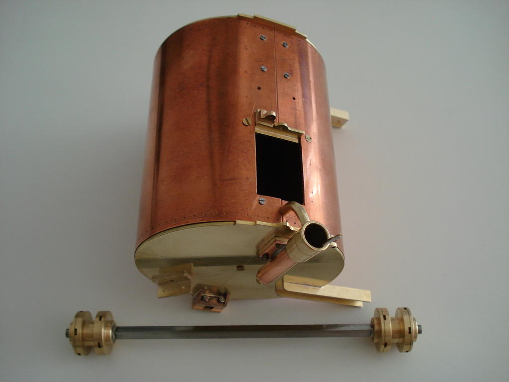
An overdue update which has established the drive chain dilemma and now has at least linked the Counter Shaft to the engine, so it can be turned over with the handle.
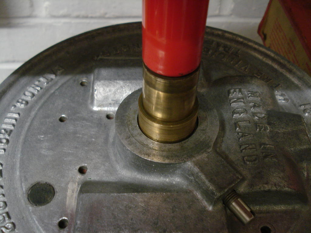
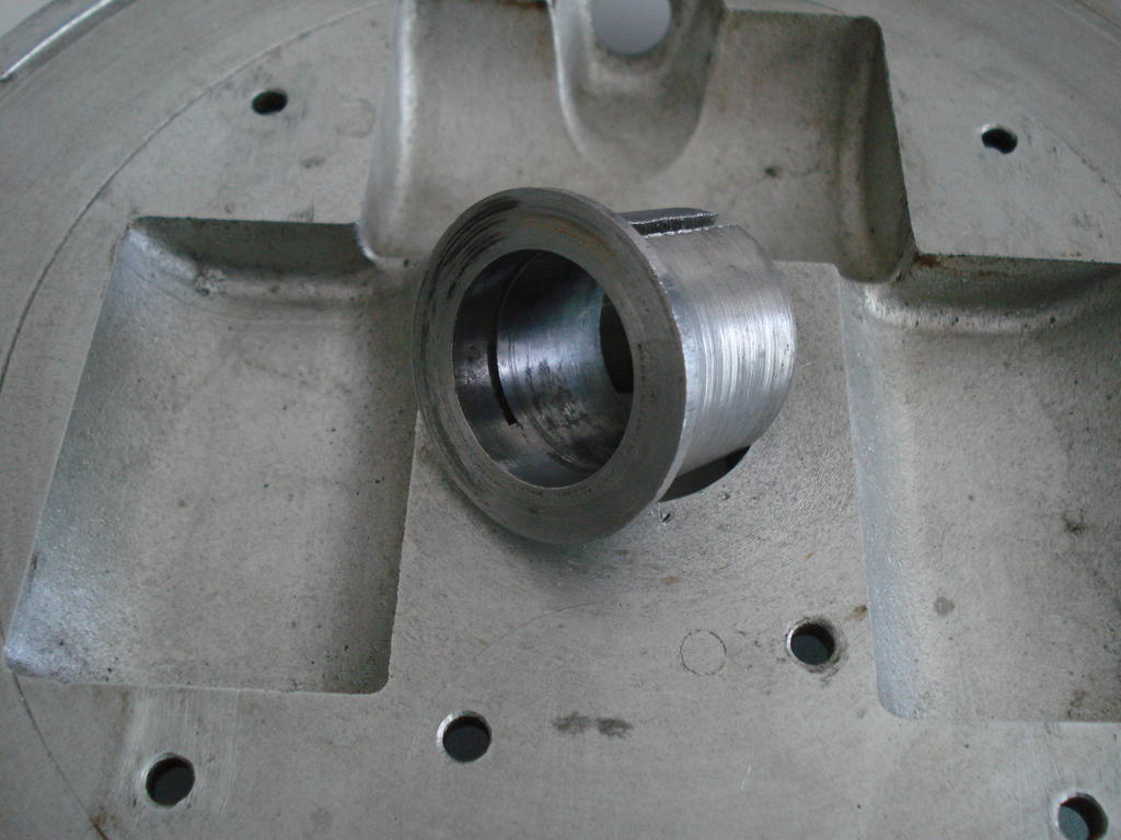
Also, I mentioned I was not happy with the badly worn split bushing that holds the Armature plate on the engine's crankshaft bushing.
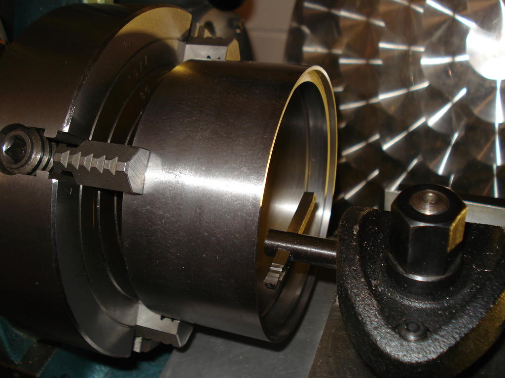
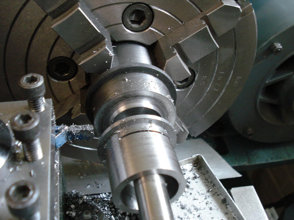
Marathon job for me, machining it from 40mm solid EN8 bar. Pressed out the old one-
Careful measuring so the new one fits as well as the old one and the bore finished undersize (0.9970") to fit the crank bushing with an interference fit-
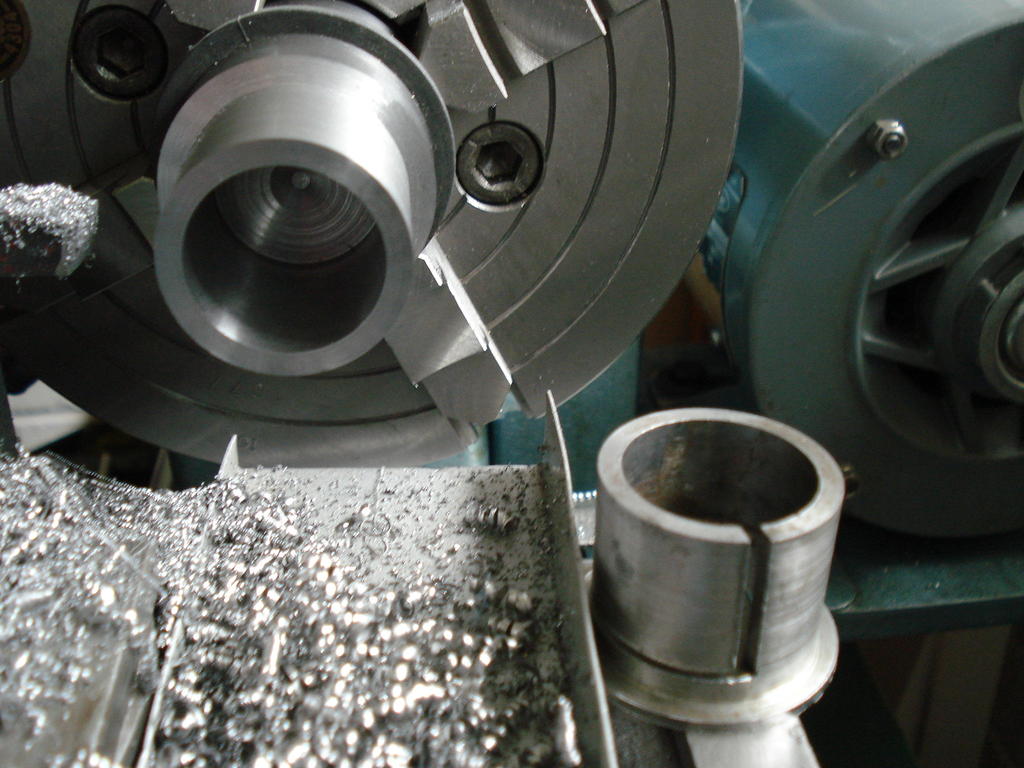
Loads of swarf later, moved it to the Mill still in the chuck to put the first slit in-
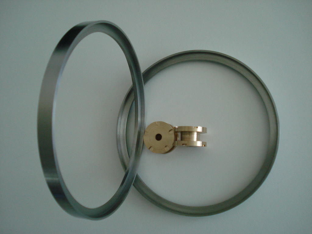
Could not see why the slit needed to be as wide as the original, so kept it 1/32" (.8mm) and back on the Lathe for parting off-
I could then fit it in a machine vise for the second slit and pressed it back into the plate-
I bottled out in the end and replaced the HT Coil - Points wire just to be sure, so was now confident that it was as good as I could get it Mag- wise.
The Armature Plate went back onto the engine as planned, a good interference fit with zero movement on the bushing before tightening the securing screw.
Final check/clean and the flywheel replaced to set the points gap and timing and the anxiety was building.
I knew the magnets were reasonable and had 'Keepers' fitted while work was done. So had no excuses left and started to check for a spark.
First few cranks of the handle produced nothing, then next turns, spotted a few faint, inconsistent sparks. I knew the mag needed to be re-energised and could take a while.
That was last week. Today, I set to it again and more cranking and checking. Finally, the sparks were more consistent and brighter, but not sure if strong enough.
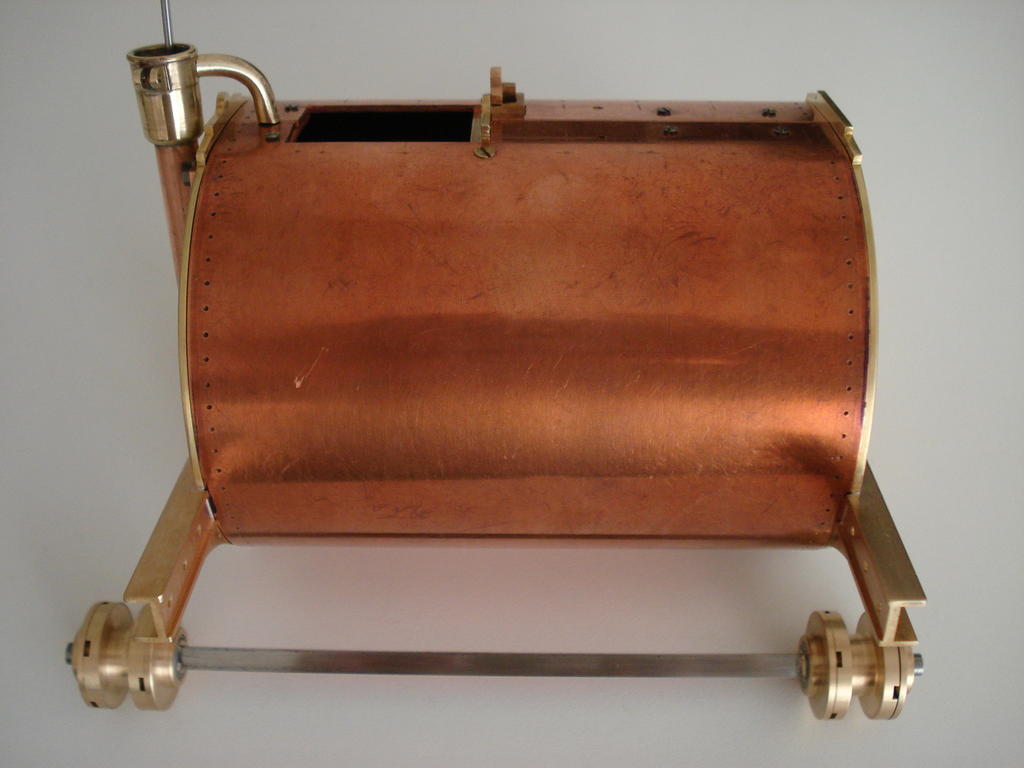
Went for it and primed the cylinder with some petroil, shoved the original Spark plug in. Cranked it up with the De-comp open, then closed it and it fired up briefly !!!.
So after over 80 years, the old Villiers has a pulse and a brief mechanical heartbeat. Next week, I'll hope to run it for longer and get some heat into it.
It will be a while before I can run/drive it....nothing to hook it up to yet.
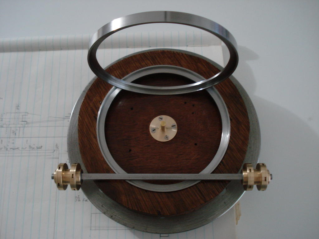
Hope these aren't an incentive to be sitting down on the jobs Norm! .............But,.... nothing to stop you stress testing them on a warm day with a beer or two!.


 . Lots of time spent shaping the Hubs to represent castings like the originals.

 .
.
") .
.
 , there were no further leaks
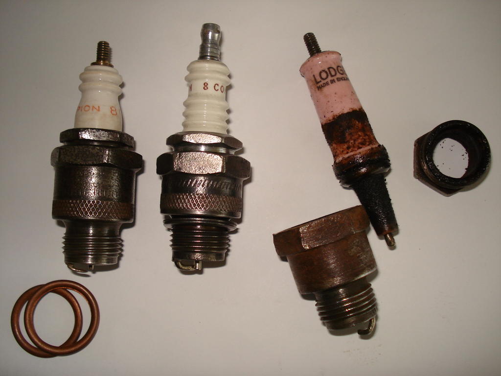
 what you have keeping secret all this time.
") .............But,.... nothing to stop you stress testing them on a warm day with a beer or two!.
.............But,.... nothing to stop you stress testing them on a warm day with a beer or two!.

Good luck and Goodbye
in Off-Topic Discussion
Posted
Sorry to hear you're having problems Alain. Would be sorry to see you go and your absence would leave a large void here.
Persevere and try Karl's advice. Don't ever let any IT gremlins grind you down. I've just beaten Ford UK into submission with their website after a frustrating 3 weeks (punch air).........
....and I'm no expert!.