There are several possible reasons for excessive oil consumption in these older 'K' engines, so I'm not sure if you have covered all of them off yet?.
Use of correct Oil. It is often experienced that use of modern synthetic blends etc in these engines can cause high consumption. They were designed for Mineral based Oils.
A good 30 wt oil of spec as specified in the manual for air cooled, splash lubrication will always serve well.
It is also possible that fitting new rings to a worn/used bore will not improve it's current condition very much. It may be worn 'out of round' , of which there is a limit quoted.
As mentioned, deglazing a cylinder can work wonders for a tired engine, but it needs to be done correctly to resemble the finish of a newly honed engine.
Kohler recommend the honing marks should intersect at approx 30degrees, and if these marks are either too steep or shallow, the oil consumption/friction can increase.
Here is an example of the correct honing finish (after a rebore)-
There is another area to check, if not already done so.
The valve guides are a possible cause and can have the same affect as worn rings on Oil use and by causing the crankcase to be pressurised, instead of running
with a partial vacuum.
These are good engines and are readily able to be rebuilt, so I for one am pleased with your clear determination to get this one back up to spec.
I hope your potential engine rebore service is local to you.
It's a few years since I had a K301 fully worked by Sutton Rebore Services and I was so impressed by their standards and prices.
The sound of an almost 'back to new' engine running as it should is payment enough.
Your engine is listed as S12D. I used this to search and find ring sets for that model (12hp, points ignition).
There is also a TRA12D, identical, but with electronic ignition, but I suspect they both use the same ring part number.
You will have to obtain a service/parts manual to double check what you need, or provide a retailer with all of your engine's model/spec and serial numbers.
Wisconsin are still in business in the U.S and suspect will be the only place you will get replacements that you can trust and be prepared to pay premium prices/delivery and import charges.......then again, it depends where in the world you are located???
Thanks, i've posted it on Redsquare. I did find someone selling replacements on the auction site and they were listed as 6206c3 bearings but this is metric and both me and my dad thought they would be imperial.
Ok, Thats me being a bit slow responding and you being on the same frequency!. Yeah, strange how the occasional metric dimension crops up in U.S. equipment.
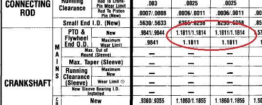
The specs in the Kohler Manual for the Crank journals each end are not round imperial fractions in Thous of an inch-
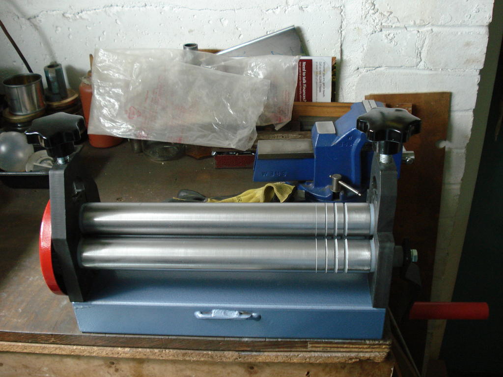
They look handy, Richard. Where did you get them from?
Hi Norm, Yes, they should do for me.
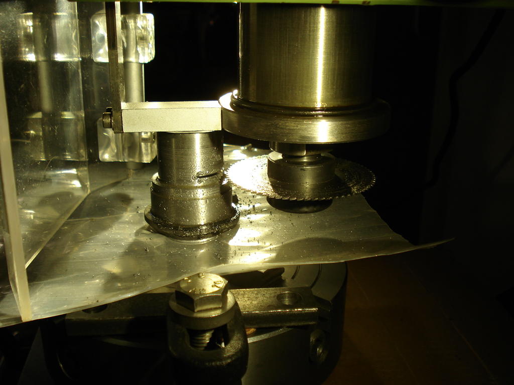
Not best quality, or hardened/ground rolls, as they were painted and I had to clean it off them to ensure the rolls were smooth enough for the finer metals I will be using.
Took a flyer and ordered off ebay. Came from Poland. Bit anxious for the last week, as overdue and no update or shipping info since 20th June. All sorted .
Just waiting for some tooling for the Mill to arrive and I'll be bending metal at the weekend.
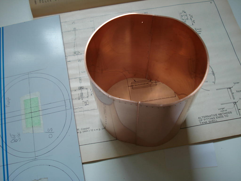
For many years, I've wanted to be able to roll sheet metal (in small sizes).
From shaping the nickel silver cleading on my traction engine to making fuel tanks and small exhaust mufflers.
So after saving up the Workshop pocket money, I've finally got a set of Mini Bending Rolls-
Quite heavy duty rollers for a 300mm wide unit and steel geared. Plenty big enough for all the jobs I have for it, and at 14kgs, just unbolts from the bench to be stored
out of the way. ....I'll get around to making some Swaging Rolls one day
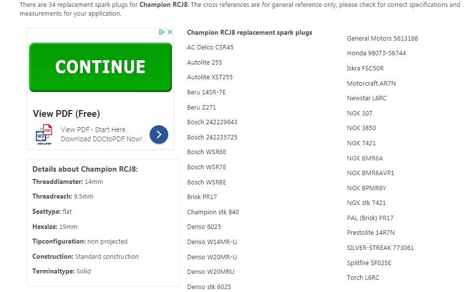
Manual reccommends Champion RCJ8 0.025" gap (unless running on propane etc). Not sure if modern ones are as good as the old ones, so here is a cross reference for loads of alternatives
Don't usually like to revisit old Topics, but this Tap came back to haunt me.
I started dripping fuel out of the Tap and apparently emptied the fuel out on the floor probably over last winter.
Having concerns that my workmanship, or the materials I had used were at fault, I took it back to find the cause.
Glad to say the bits I did were not faulty, but found the fuel was leaking out of the lever end.
So I stripped it down on the understanding that if I can't fix it, they will have to replace the whole unit (if they can find one).
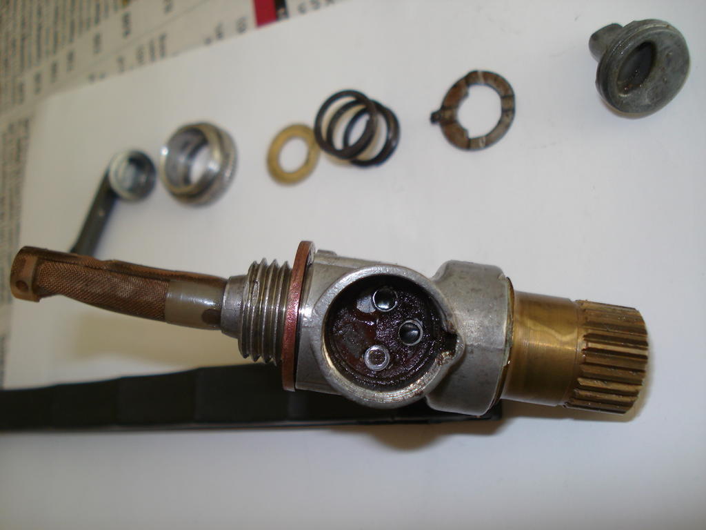
Talk about over engineered!. Seven separate parts just for the tap lever control !, including a plastic type seal which had dissolved/rotted which was causing the leak-
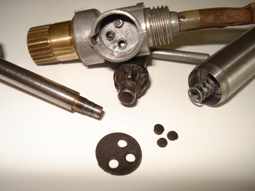
So as usual, I hit the challenge and went for making a replacement seal from fuel resistant 1.5mm thick nitrile/nylon reinforced rubber.
I had to make 2 special punches that could cleanly punch through the tough layers and in the correct positions-
Glad to say that when the cleaned parts were assembled and the tap fitted , there were no further leaks. Hope I've seen the back of this one now.
No real update yet and haven't had a chance to concentrate on test running this, but have primed the Carb float bowl to test the float valve which I 'Lapped' to ensure a good fit/seal.
Left it for a week to see how it fares. I suppose I really want to cover all the points that will make it work before fueling it up.
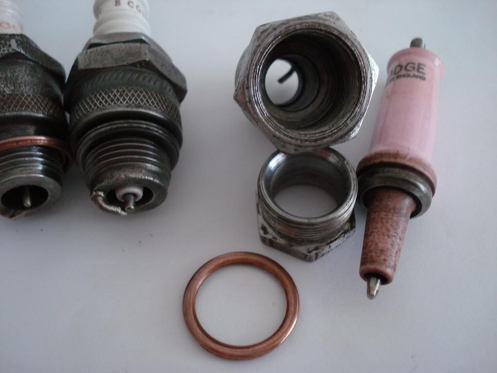
In the meantime, I wanted to give the Spark Plug stock a good going over.
I have the original 8 COM in the engine currently, but don't really want to rely on it. So I have 2 other 8 COMs and a Lodge BBL.
These I've stripped out and cleaned, as they all can be dismantled for cleaning. Did the Champions first, one is 1930s (left) and the other is 1950s.
The 50s one cleaned up best, but turned out to be dead. No continuity in the central electrode. The 30s one is perfect, 0.5 ohms resistance top to tip-
Had doubts about the Lodge BBL, but after sorting the loose body electrode, it cleaned up ok-
Has a reading of just 2.8 Ohms, so also good. This one is on the higher temperature side of the 'Warm' range that 8 Com is in and is good for Oily running engines.
Also have a good Vintage Lodge CV and hope to be able to test them all out on it, but I have to make 2 different threaded (Thumb Nuts) for them.
2 early ones are threaded UNC and the CV is 2BA !. Hope to update soon.
hi i have recently purchased a lloyds auto scythe and wondered if any one would have any info on a lloyds auto scythe please . or any brochures ect , many thanks alec hooper
Hi Alec,
Do you still need this info?. I may able to help, but not this week.
I decided to temporary fit the head just to keep things together, till I get the parts I need. That is when I found another PO's bodge. One of the head bolt holes by the exhaust valve, has been tapped out the 3/8th UNC. Plus the bolt used is slightly longer with a longer shank. Not much I can do about the hole, but the bolt I will cut down to the length of the others and run a die down the shank, to get the same amount of thread.
Good work on the head Norm, slightly higher Comp Ratio .
An early 70s style head with the plug hole central. Later version around 1974 was a heavier casting and the hole over the exhaust valve.
The bolt that nearly (or does) break into the exhaust chamber is a pain on these. If a head bolt is going to shear when initially undoing, bets are on it will be that one.
Can't remember if it's number 7 or 8 in the sequence, but was glad I put a Stud in there in my last one so it only ever needs the nut undoing without disturbing the stud.
A great thread and wonderful workmanship . Ignition - unless I’ve missed it, there’s no mention of the condenser, has it been changed? Judging from the number of faulty / weak condensers that I change on not quite so old engines, it may be worth a punt.
Thanks, and yes I did briefly mention the condenser situation in post #14 on page one.
I agree with you on the later canister (m1750 type) versions regarding their reliability/inconsistency. If this engine had that style, I would have replaced it irrespectively..
I don't have a pic of the back of the brass condenser/points box, but it is solidly filled.
The condenser, being the original patented design of 1921 is constructed using Mica sheets in between the aluminium plates (according to the 2 Authors of the books I have).
On this version, the whole unit is fitted into the box and then flooded with molten bitumen, so it's hermetically sealed within.
Modern Villiers condensers (mid 30s onwards-ish) were constructed using waxed paper as an interleaved insulator and these have a tendency to break down quicker (as per the books).
I decided to give the original one the opportunity to prove itself in it's quality/reliability based on the condition of the original points faces (platinum), where there was only the slightest sign of 'arc pitting' (coil/condenser side) and tiny peak on the earth/ground side, which could indicate a possible slight over capacitance when it was last running.
There are statements in the books that say these old versions rarely fail . I'll know where to look if a problem shows up.
The progressive condition of the spark was consistent using several spark plugs (non resistor).
So with a few backups, I'm going to run it initially on the original plug (Champion 8 com).
The worn Points Heel was likely to be a possible problem, but on assembly, the clearance/lift was way more than enough to set the points gap .
On 6/5/2019 at 10:58 PM, Stormin said:
Well done Richard. It'll soon be purring like a kitten. As near as a two stroke sounds to a kitten anyway.
Thanks Norm. For the few revs it's done so far, it seems to have a bit of a 'bark' to the exhaust note.
I'm expecting this to run at around 1500-1750 rpm, so a sound like the old vintage Bikes of the age and a bit noisier .
I'm sure if you can't find a set of wheels, carriage or cart, a man of your capabilities can make some.
A bit more than I could deal with without finding more large tooling like bending rolls and a larger welder Norm. A long search for the correct size may be the only way.
I reckon sorting the mower will be quicker.
On 5/10/2019 at 8:26 PM, Alan said:
Very nice Richard. Now we know what you have keeping secret all this time.
Not sure if it was worth the wait for people, but hope it is seen for what it's worth.
An overdue update which has established the drive chain dilemma and now has at least linked the Counter Shaft to the engine, so it can be turned over with the handle.
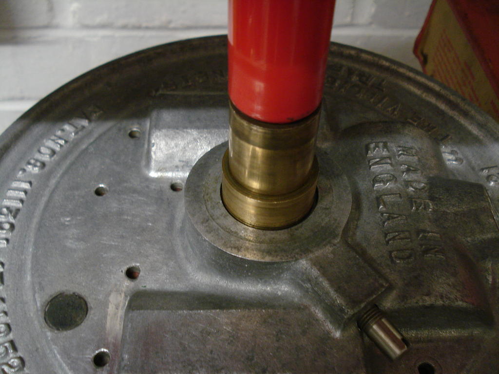
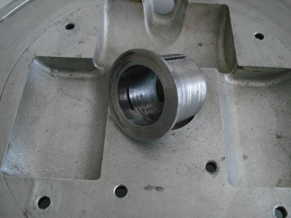
Also, I mentioned I was not happy with the badly worn split bushing that holds the Armature plate on the engine's crankshaft bushing.
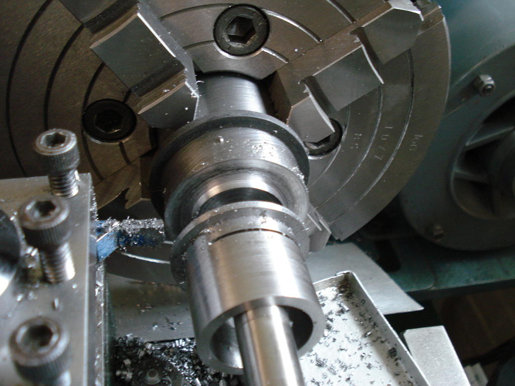
Marathon job for me, machining it from 40mm solid EN8 bar. Pressed out the old one-
Careful measuring so the new one fits as well as the old one and the bore finished undersize (0.9970") to fit the crank bushing with an interference fit-
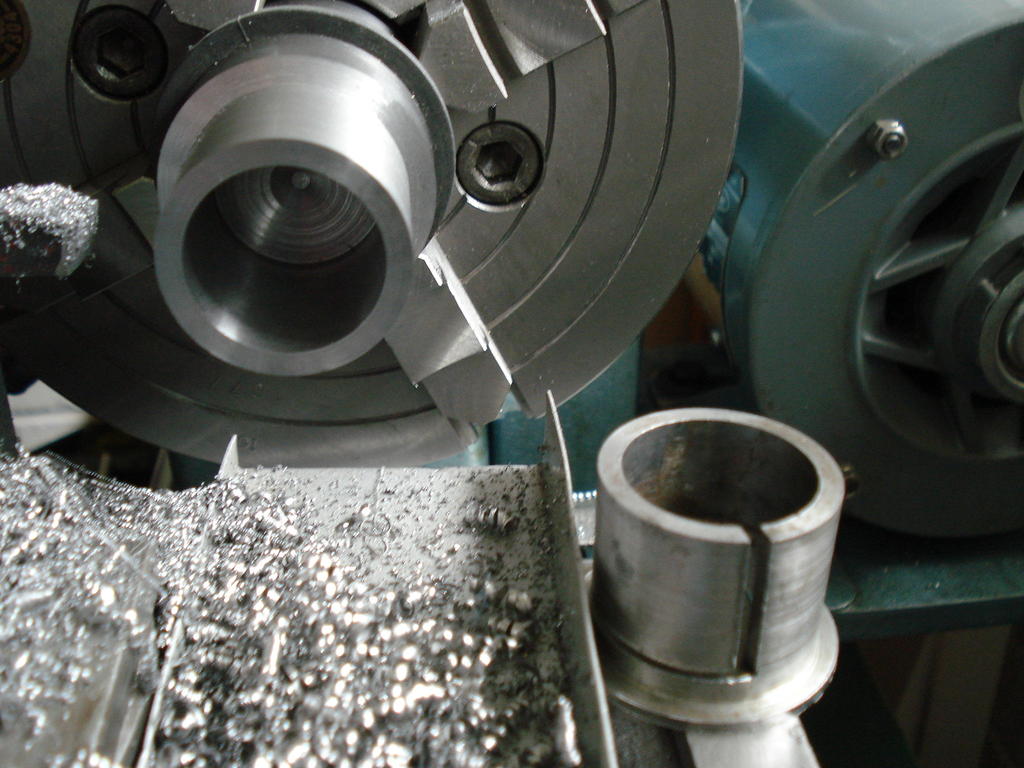
Loads of swarf later, moved it to the Mill still in the chuck to put the first slit in-
Could not see why the slit needed to be as wide as the original, so kept it 1/32" (.8mm) and back on the Lathe for parting off-
I could then fit it in a machine vise for the second slit and pressed it back into the plate-
I bottled out in the end and replaced the HT Coil - Points wire just to be sure, so was now confident that it was as good as I could get it Mag- wise.
The Armature Plate went back onto the engine as planned, a good interference fit with zero movement on the bushing before tightening the securing screw.
Final check/clean and the flywheel replaced to set the points gap and timing and the anxiety was building.
I knew the magnets were reasonable and had 'Keepers' fitted while work was done. So had no excuses left and started to check for a spark.
First few cranks of the handle produced nothing, then next turns, spotted a few faint, inconsistent sparks. I knew the mag needed to be re-energised and could take a while.
That was last week. Today, I set to it again and more cranking and checking. Finally, the sparks were more consistent and brighter, but not sure if strong enough.
Went for it and primed the cylinder with some petroil, shoved the original Spark plug in. Cranked it up with the De-comp open, then closed it and it fired up briefly !!!.
So after over 80 years, the old Villiers has a pulse and a brief mechanical heartbeat. Next week, I'll hope to run it for longer and get some heat into it.
It will be a while before I can run/drive it....nothing to hook it up to yet.
Hope these aren't an incentive to be sitting down on the jobs Norm! .............But,.... nothing to stop you stress testing them on a warm day with a beer or two!.
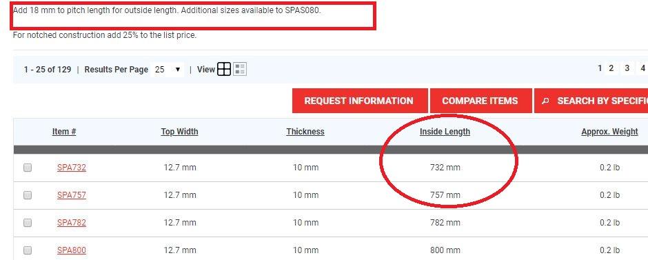
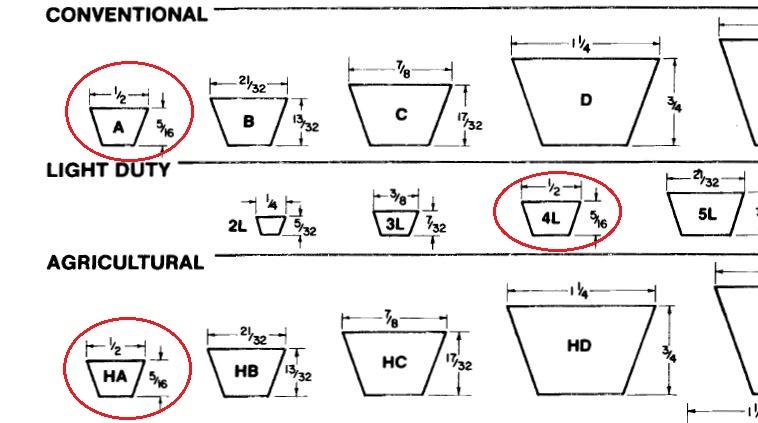
Ah!, forgot you'd fitted other pulleys. I suspect you had better stick to SPA Section Belts. The Section is different to 'V' (13mm x 8mm) SPA is 13mm x 10mm.
Which means you may have to stick to 732mm. No experience with that type.
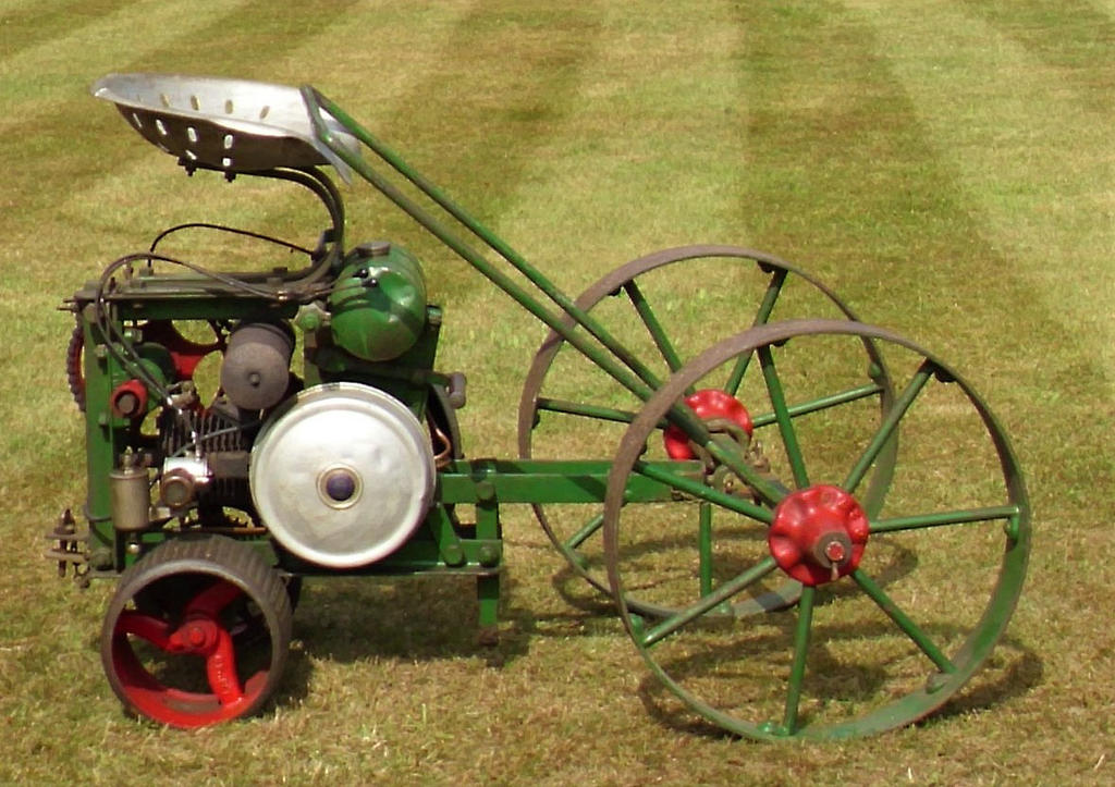
That's one beautiful looking piece of machinery. Here's hoping you can get it running, then all you'll need is a period mower to push.
I am inclined to agree about it's appearance Norm. I feel it has that simple 'Bolty' look about it. Plus the combination of the colours and bright parts.
I've been struggling with progress, as I hit a wall trying to obtain some drive chain which is only used on a few vintage machines and motorcycles.
Zero response from two attempts over the last week, then tried another this afternoon where I got an almost immediate and positive reply.
So I'm over my last hurdle of finding parts hopefully, but I think I will have to make another obsolete part for the engine, not happy yet?.
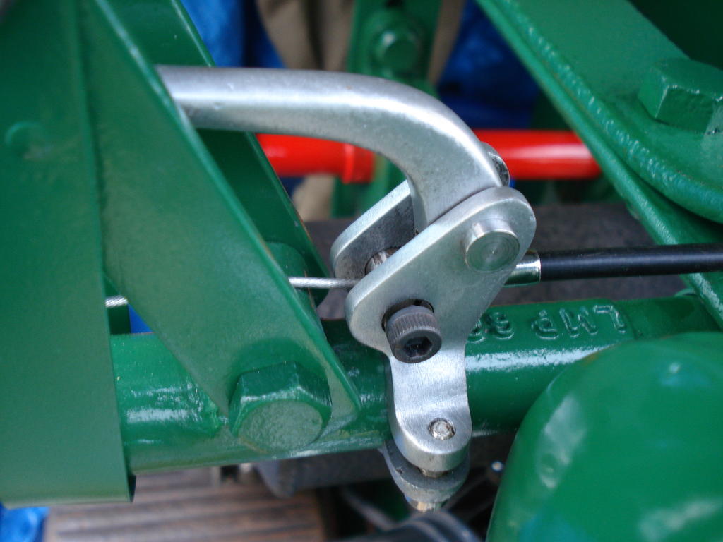
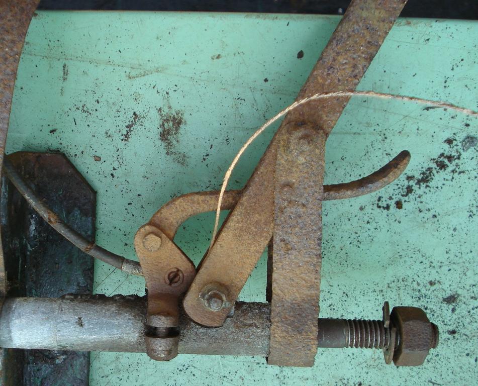
Have made a little progress and assembled the Clutch/cable/lever, but had a problem with the lock screw gripping the cable tight enough in the lever.
Lot of tension in the clutch spring to overcome, so I've made a temporary lockscrew with a socket head to be able to tighten it better-
-
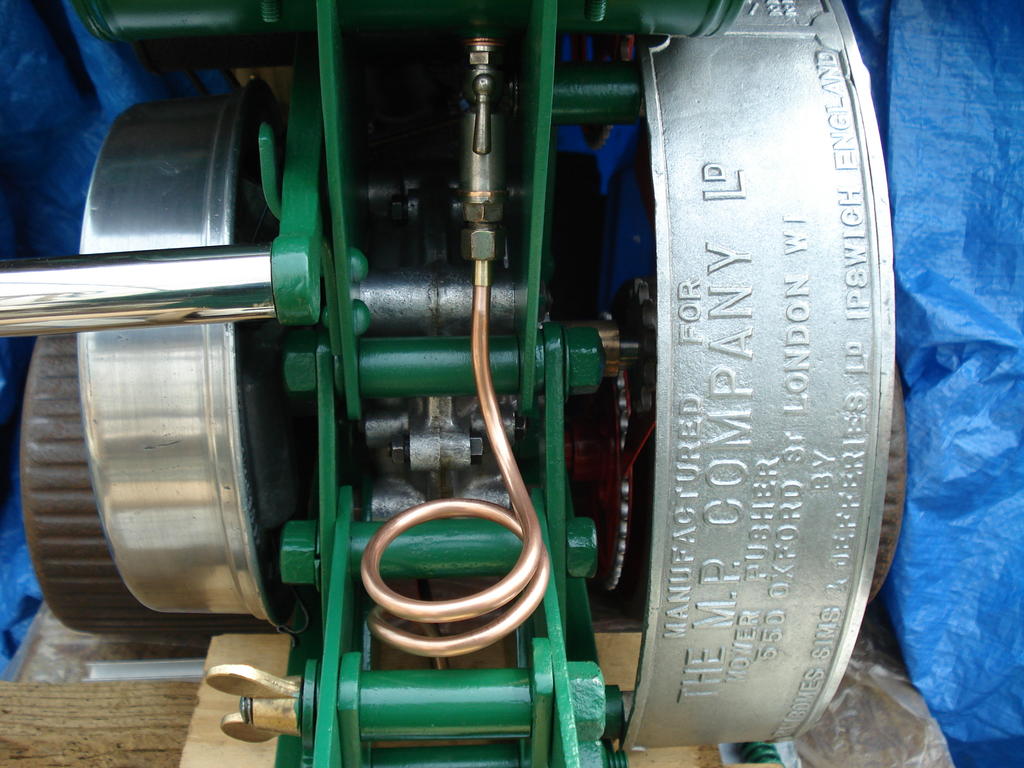
Decided on the fuel pipe routing, keeping it within the frame and shortest distance. Original route can be seen in the 'as found' pics.
Just the Carb end to fix and solder, as this pic was taken when a trial fit was made, the coil position etc is now tidier -
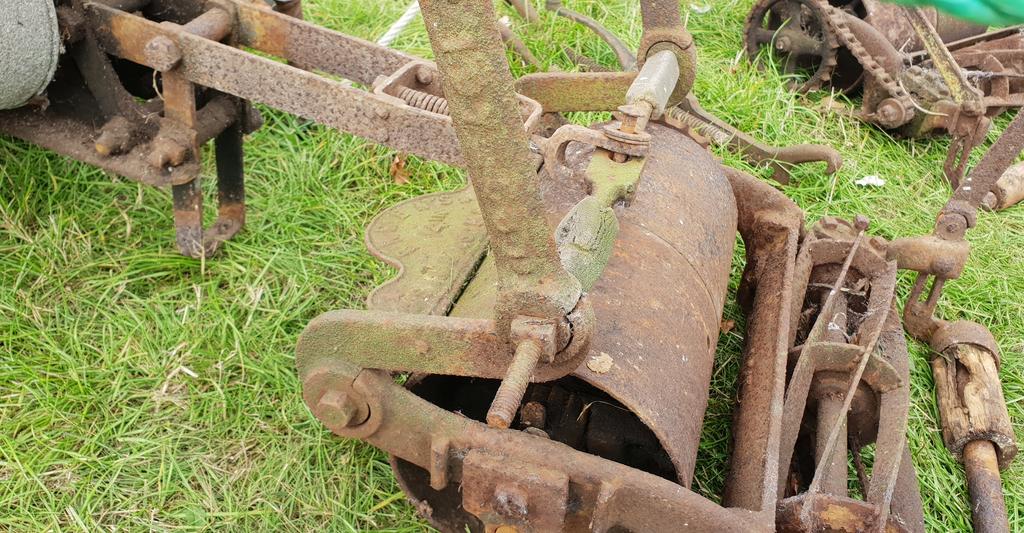
As for finding a mower to attach it to, well it did come with the original mower it used to push back in the 1920s and here is a pic of how it attaches-
One or two examples can be seen around the show circuits affixed to a mower, or like this example (off the Web) where an axle from a different machine has been adapted to fit-
Would be nice to find a set of similar wheels to make an axle up for this one I'm working on. When it's fitted to a mower, the turning circle is enormous.
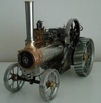
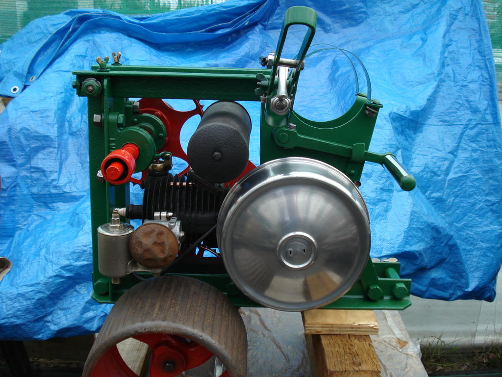
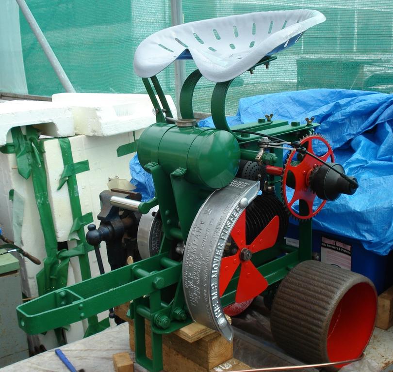
Well, those of you who have been watching this have seen glimpses of bits that don't really mean much.
So I have decided to let you know what this thing is, despite having a fair way to go before (if) any mechanical life can be breathed into it.
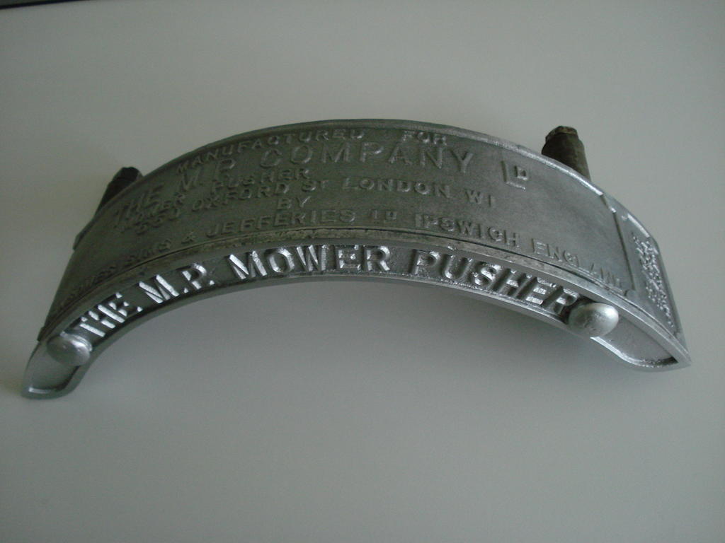
It's 90% there, but still have the drive chain hurdle to overcome. So bearing in mind that it's nothing really spectacular, it is uncommon. This is what it is -
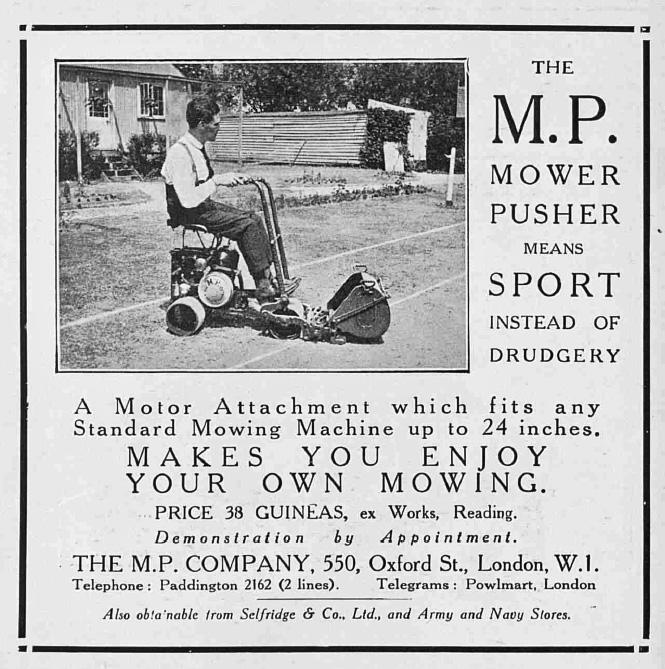
This ad is from the Tatler Magazine of Aug 1922. I have other images, but are copyrighted and not for public use.
Designed to provide assisted (Ride-on) power to existing, manually pushed lawnmowers at the time.
So it can be called the first known British Ride-on that was available to the average domestic household. Earlier large private Estate/Municiple ride-ons were available.
They were built by Ransomes, Sims & Jefferies for the MP Co.
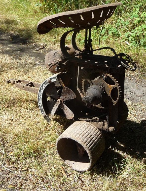
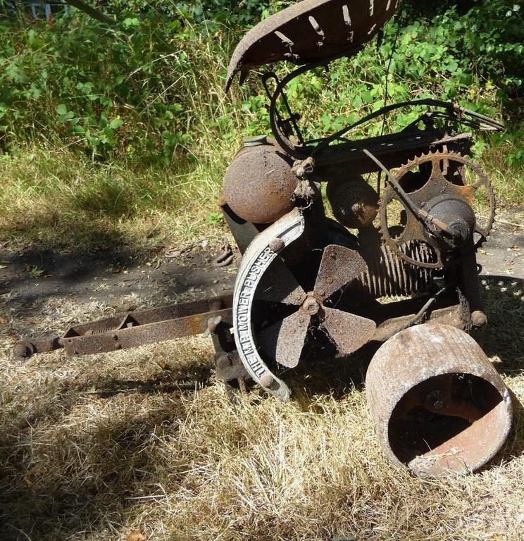
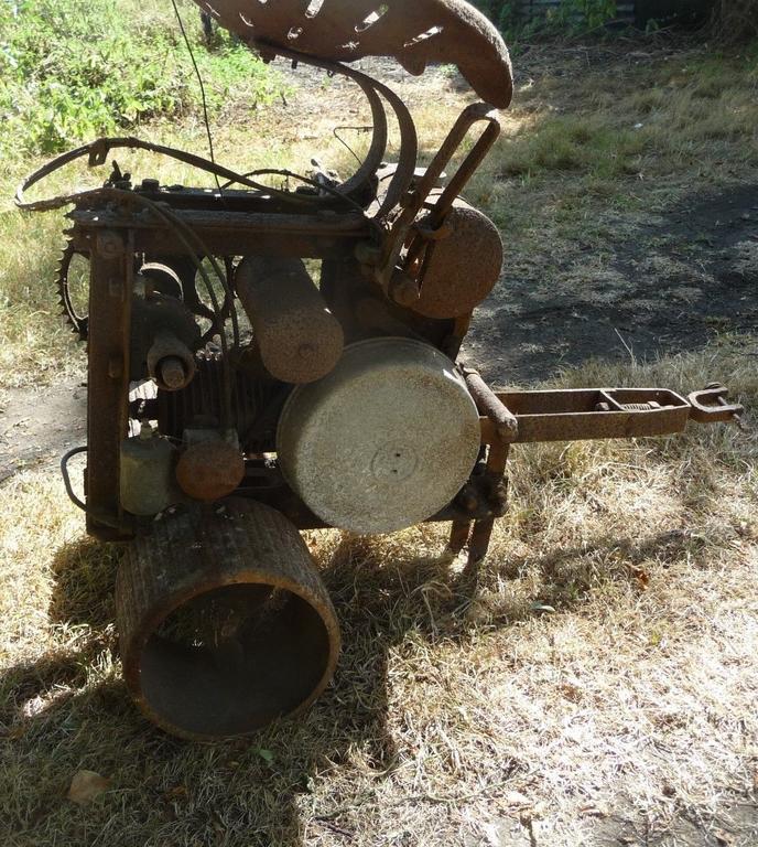
At the start of this Topic, I mentioned the condition and it's neglected existence, albeit virtually complete. This is what it looked like-
Not my pics, but shows it was in a bad state.
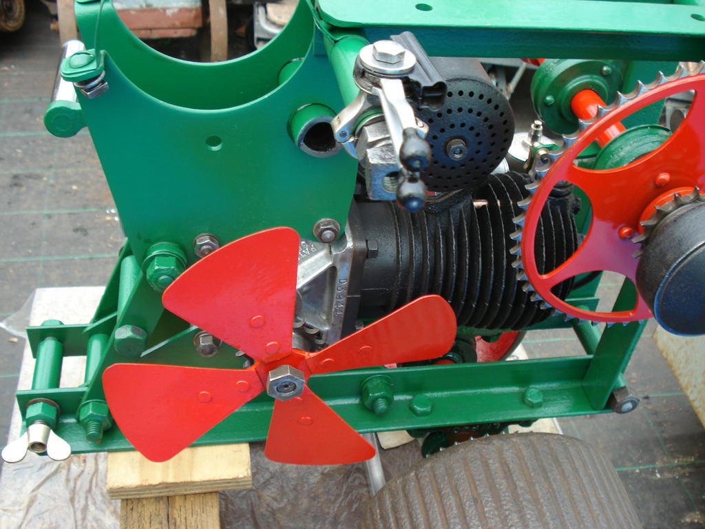
It's debatable whether to replace some damaged/missing parts like the (left) lower end section of the Fan cover-
I suppose it is really part of it's existence, hard knocks 'n' all.
What I have found strange, is the varying immunity of certain sections to corrosion. Some very thin metal sheet parts are hardly eroded, but heavier, thicker spring steels
are heavily pitted?. All exposed to the same levels of weather. Suppose it's lucky to be able to save/use most of it.
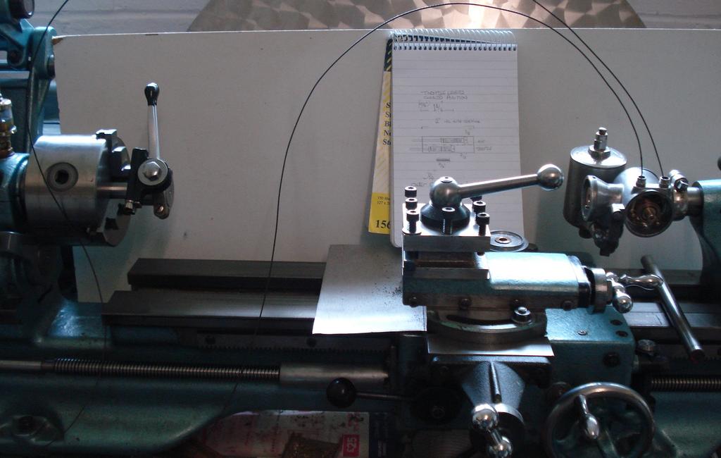
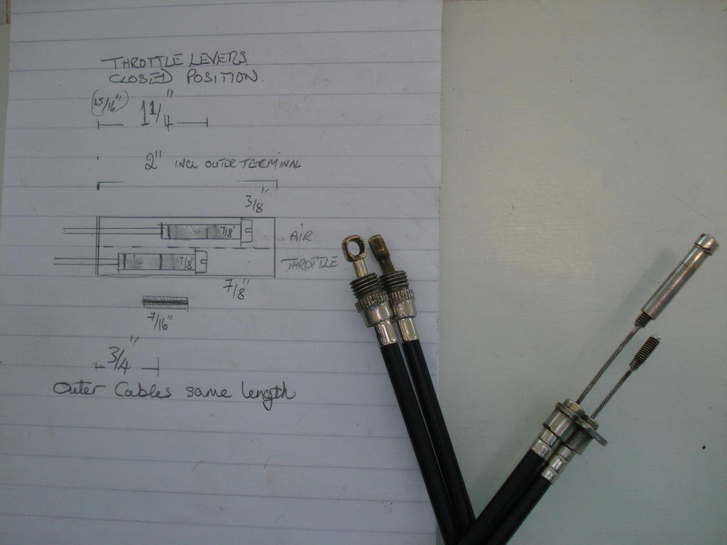
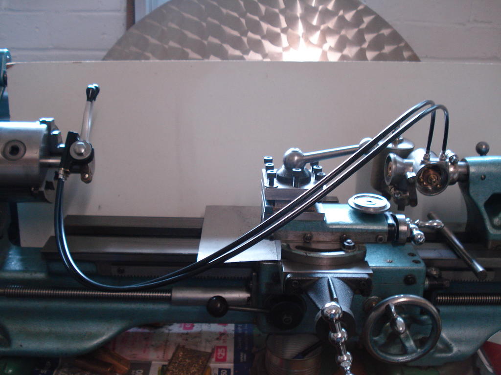
Today, I've made up the Cables for Carb controls. Tricky job and I decided to set it up in a way that would be easier to manage.
Bolted the Carb to my Lathe tail stock barrel and the Levers to a bar in the Chuck-
The inner cables were different length from a donor source and I had make them both the same length and produce new outer bowden cables.
Lots of careful measuring, as the 1926 Carb manual says never dismantle the Lever and cables !!. I had no choice.
So with a lot of cleaning to get the solder to take on the shortened inner cable, all the ends soldered up and the bits fitted correctly-
And relieved to say everything operates/adjusts correctly -
Most of the control levers were in a bad state as mentioned way back and showed the end result, but here are a few of what they were like-
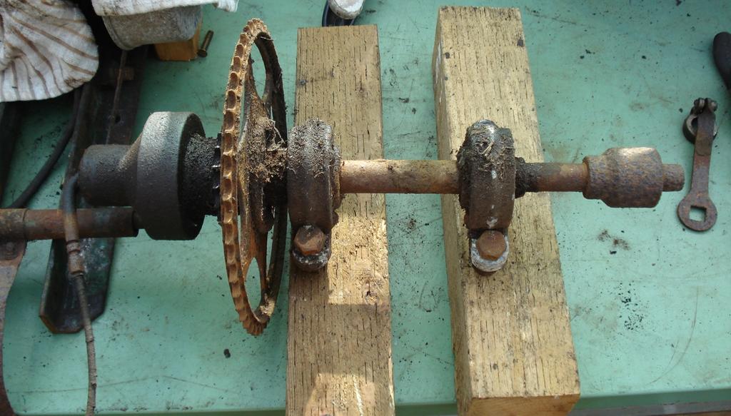
...... the Counter shaft -
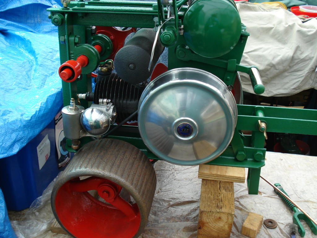
So here is what it looked like as assembly progressed-
And to date-
If I can get it running, it will be one of only a handful of working examples in collector's hands. Hope to have more updates soon
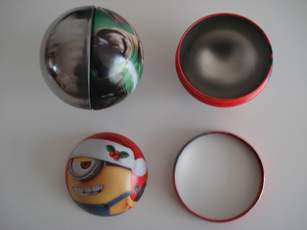
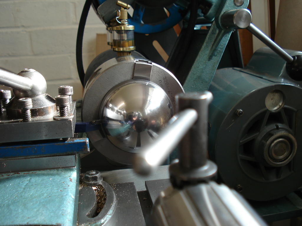
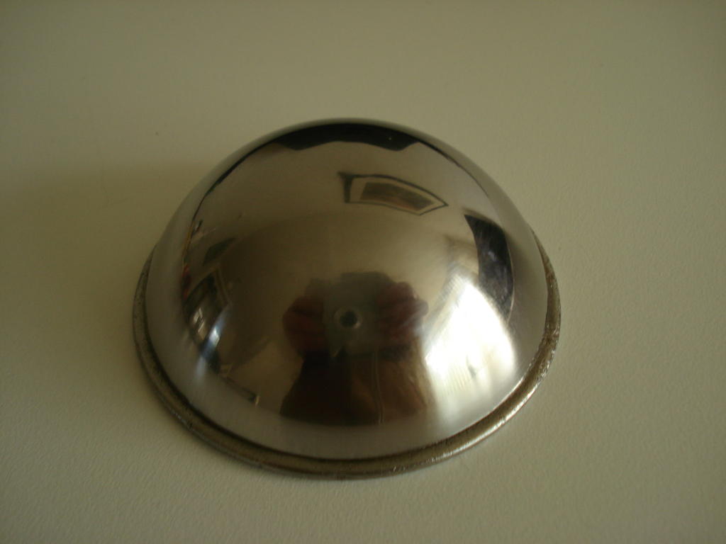
The answer is 'Balls' Norm! ....................................Yes the item is the original, but I have added the dome to it.
Back around Xmas, I observed some Kiddies Ball shaped tins that contained chocolate of some kind. Managed to get hold of a couple and found one without any significant damage. Measured pretty close to the radius, so went for cutting a slice off for a test.
First job was to clean off the paint/ink to see what the finish was to the steel (top left).
I then had to polish it and measured the amount needed to slice off for a sample and what method to slice it off with ( bottom left)-
First go was 3/64"(1.2mm) short, so went for it on the good cleaned off section -
Cleaned up and tinned with solder, it was soldered to the original, which was not easy as had to use passive resin flux, but went ok.
Had a good coat of fuel proof lacquer and settled for an old small cafetiere s/s gauze filter cut to fit as a dust collector. All done and will go nicely with the now very tidy Carb.
Dragging behind schedule recently, but have nearly finished several parts which should all come together next week for a more bulky update and to probably reveal the ID of it.
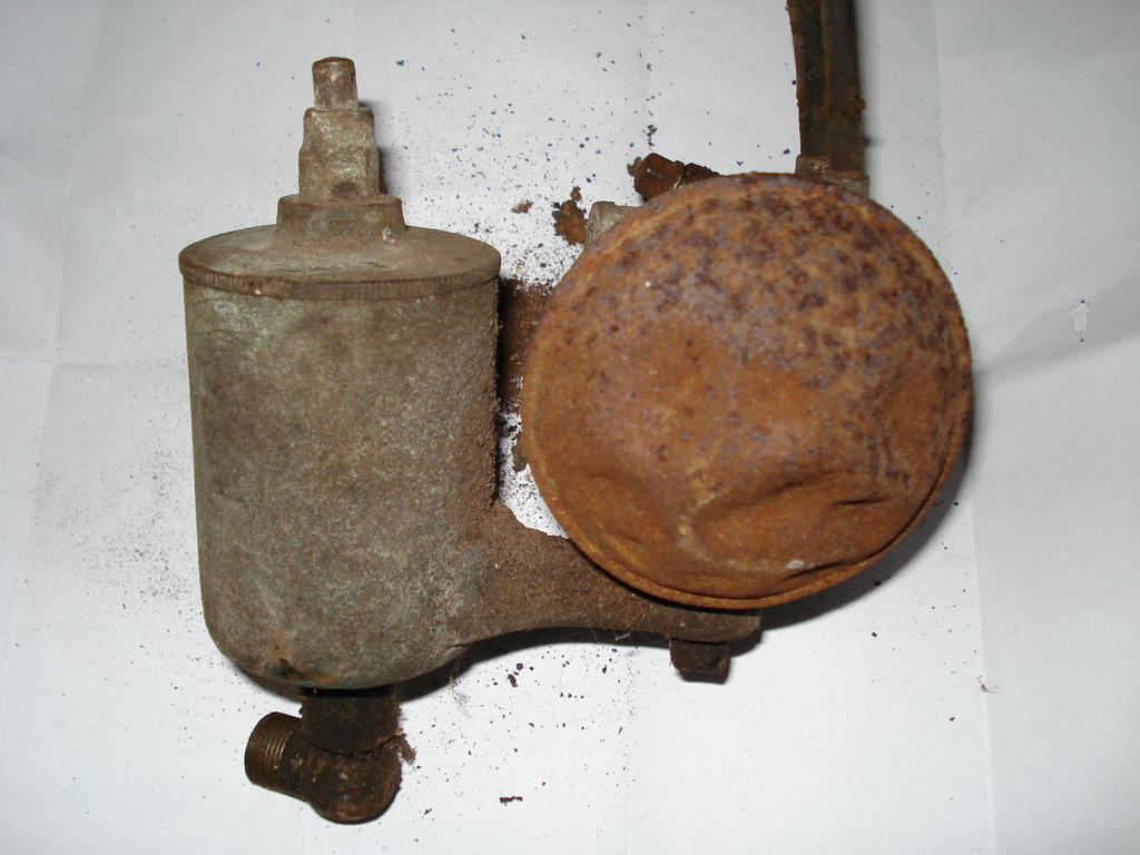
Just to come back to the carb for the near impossible easy repair, I've repeated an image here that is in the link of the previous post to save any toggling for comparison.
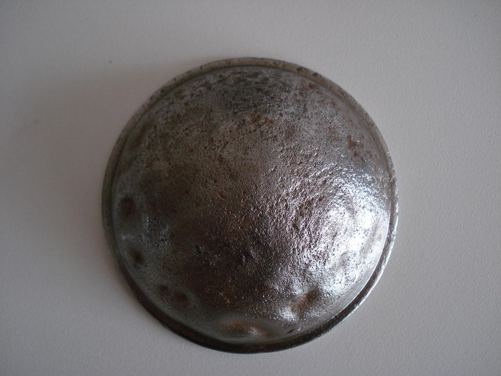
I was presented with this dented mushroom Air inlet cover. Originally this was a bright shiny nickel plated cover, but as can be seen, the old 'anger scars' and corrosion is severe-
I can't call it a filter, as there is no mesh. It is not possible to get all the dents out. I did consider (briefly) taking the old outer cover off and
spinning up and soldering on a nickel silver one.
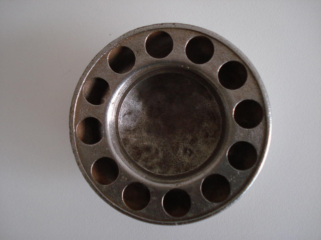
This rear view will show you the lack of filtration and I will probably spring a strip of oiled scouring pad in to cover the holes-
And the front, which I was not happy with, where just filling and painting would actually be more work than the idea I had to fix this much quicker.
I came up with this and now only requires a coat of lacquer after cleaning up the outer edge -
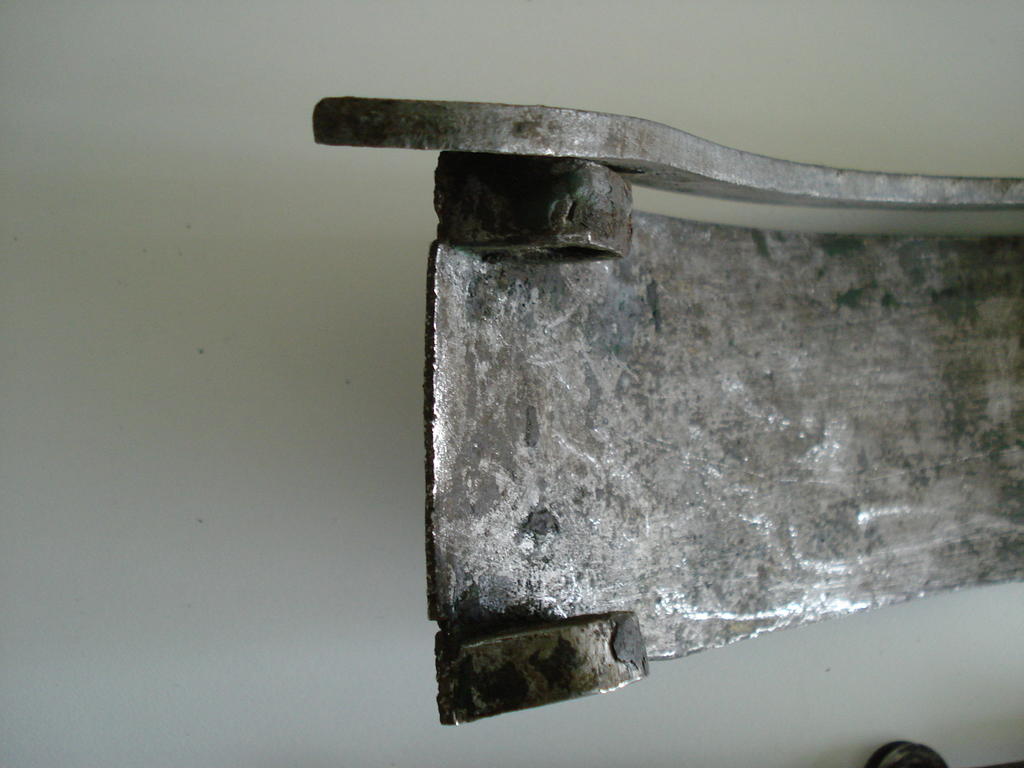
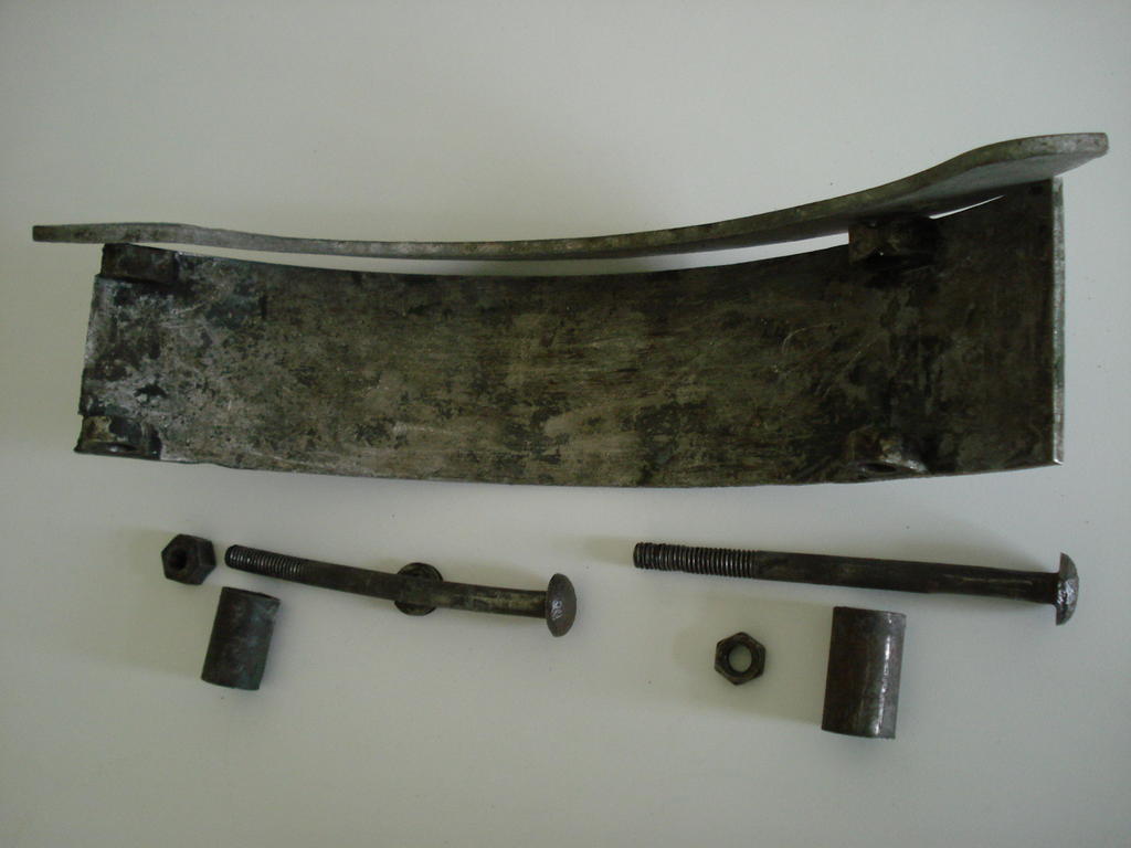
The Cooling fan shroud is of thin cast aluminium and has had a bad hit low down at the front, snapped a piece off and bent everything, also one wrong size nut fitted-
Having to make additional spacers so that the bolts do not crush (again) the Ali plate when tightened.
I'm carefully heating parts to ease the stresses before straightening. I'm using soap to indicate the temperature and it's going well, should be seen fitted next week.
Clutch cable is done but need to trim to length on the machine. Throttle cable (outer Bowdens) need to be replaced (tricky). Seat is finished ready to fit.
Fuel pipe is a challenge, as the two different tapered nipples were originally brazed to the old pipe, so I had to cut off the big one and bore out to fit on the new pipe.
The smaller one I scrapped and turned/machined up a new one and both will be soldered on this time .
Having problems with the final hurdle, namely the drive chains. These must be replaced, the originals were just welded together with rust, as they
were removed and left on the seat over 80 years ago, Spec is unobtainable now?, no sign of any old stock, so may have to rob from a scrap/donor machine If


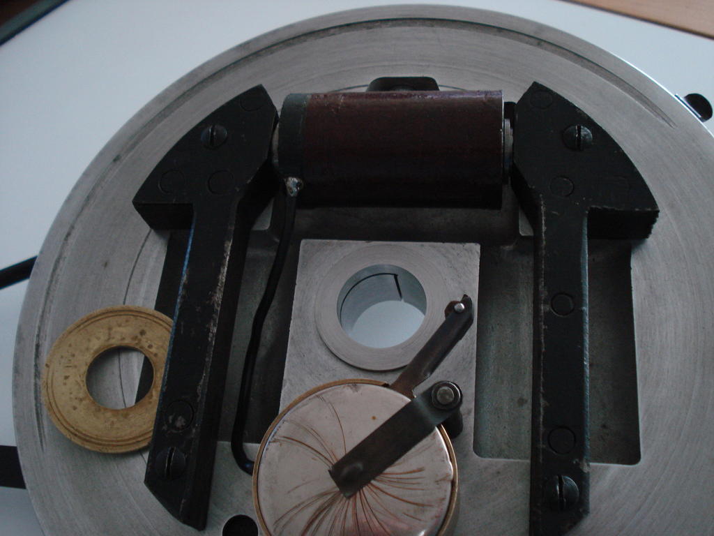
 . Marked the adjuster knobs on the top Roll so I knew each is at the same setting-


 .
.
") .
.
 , there were no further leaks
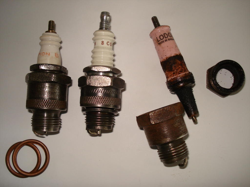
 what you have keeping secret all this time.
") .............But,.... nothing to stop you stress testing them on a warm day with a beer or two!.
.............But,.... nothing to stop you stress testing them on a warm day with a beer or two!.

 Here's hoping you can get it running, then all you'll need is a period mower to push.
 -
-
 ....................................Yes the item is the original, but I have added the dome to it.
Spark Plug
in Ride On's
Posted
There are several possible reasons for excessive oil consumption in these older 'K' engines, so I'm not sure if you have covered all of them off yet?.
Use of correct Oil. It is often experienced that use of modern synthetic blends etc in these engines can cause high consumption. They were designed for Mineral based Oils.
A good 30 wt oil of spec as specified in the manual for air cooled, splash lubrication will always serve well.
It is also possible that fitting new rings to a worn/used bore will not improve it's current condition very much. It may be worn 'out of round' , of which there is a limit quoted.
As mentioned, deglazing a cylinder can work wonders for a tired engine, but it needs to be done correctly to resemble the finish of a newly honed engine.
Kohler recommend the honing marks should intersect at approx 30degrees, and if these marks are either too steep or shallow, the oil consumption/friction can increase.
Here is an example of the correct honing finish (after a rebore)-
There is another area to check, if not already done so.
The valve guides are a possible cause and can have the same affect as worn rings on Oil use and by causing the crankcase to be pressurised, instead of running
with a partial vacuum.
These are good engines and are readily able to be rebuilt, so I for one am pleased with your clear determination to get this one back up to spec.
I hope your potential engine rebore service is local to you.
It's a few years since I had a K301 fully worked by Sutton Rebore Services and I was so impressed by their standards and prices.
The sound of an almost 'back to new' engine running as it should is payment enough.
Regards