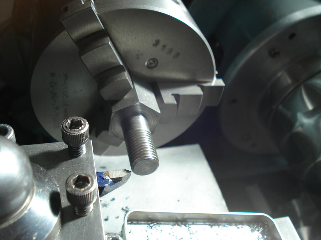
Had some lathe and milling machine time in recently. Started on the wheel for the front caster. Had barely enough 40mm dia EN8 Steel to make the hub and leave enough for the drive coupling.
Had to work really close to the chuck jaws, which was going fine with light feed, then I noticed the 'in-feed' movement of the parting tool went 'light' and easier !. I withdrew the tool and found it had failed !.
As I bought it in a modestly priced set 38 years ago and just lightly stoned the cutting edge now and again, it has served me very well-
I finished off with a narrow HSS type with no issues.
Indexed and drilled for the spokes on the Mill with barely 1.5mm clearance between rotary table wheel and chuck ! -
Also added an angled grease point and made the bronze bushes to be pressed in later-
I decided to keep the original engine output drive clutch bell and make a driven plate to replace the original Mower Clutch plates to form a coupling.
This would allow for any tiny misalignment of the engine and the reducton unit.
The load transfered through this part will be much less than it was orignally handling in a Mower, but I wanted it to be efficient and reliable.
Ordered a 105mm x 4mm laser cut mild Steel disc and meanwhile, I made 6 bronze wear pads -
The slitting saw used is only 0.0125" (0.3mm) thick. These pads were soldered to the dog spokes of the plate where they will contact the recesses in the clutch bell.
The plate was then set up to drill the 6 HT fixing screws to the boss-
Once I had cut the keyway in the boss, I pressed the plate with the drilled and countersunk holes onto the boss and finished fitting the screws. i need to file out the keyway in the plate to depth.
The bell drive recesses needed weld metal added where they were worn from mowing since 1954, but were not bad at all -
The caster wheel is at the final assembly stage. My reasons for using surplus thick walled steel tubing for the rim left over from my previous Water Cart wheel making becomes clear.
It all fits and allows me to re-use the wheel jig for accurate assembly ! -
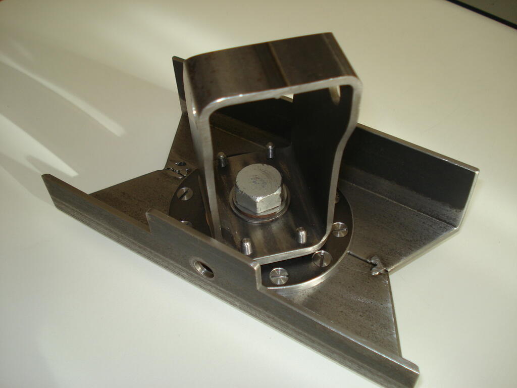
Thank you Gents!. Still learning as I go and making reasonable progress. Finished the parts for the front caster assembled here with a temporary bolt, so just the wheel to make-
I had to make the 1/2" BSF Pin Bolt to ensure a good fit and with fine adjustment. I have some 15/16" AF high carbon Hex steel, so set to and turned one up on the lathe-
Also made a nut.
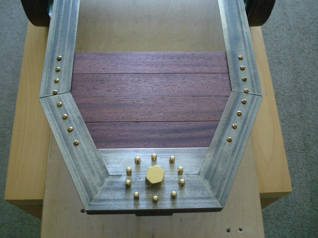
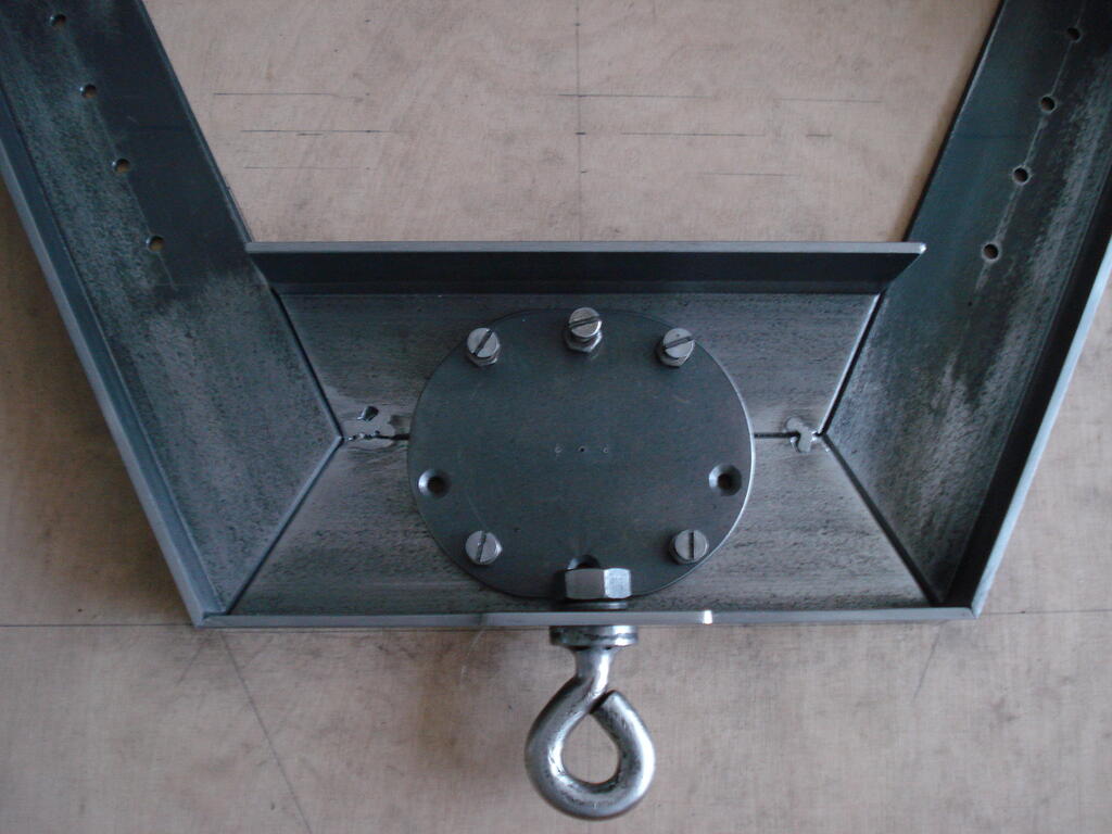
I bit the bullet and started 'tacking' the frame joints and managed to continue with reasonble weld joints to form a strong frame. I wll need to get the upper surface joints properly done.
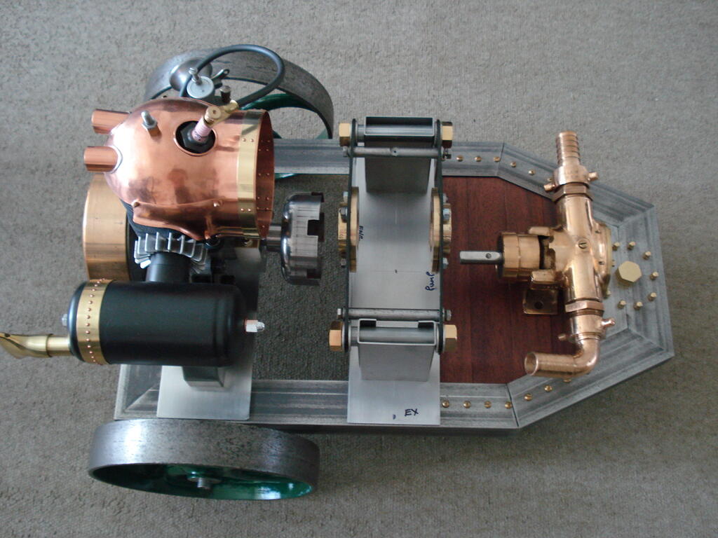
The mahogany planks have been cut and temporarily fitted for trimming to bring the surface level with the frame's surface. Embelishments include a brass nut cover to keep it weather tight-
.........and we all like to 'trial assemble', so this gives a better image of the project-
Hi Mike, Good collection and restoration work I presume on your behalf. A fellow Countryman of yours who left the Forum several years ago, also was a Briggs collector.
His name was Matt, but left us many images. Here is a link to just one of his contribrutions, but if you scan for his others on pages 4 & 5 also of this section, you'll find many-
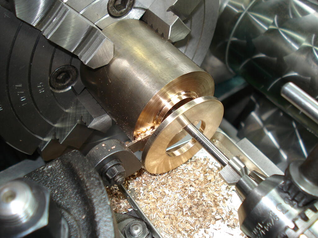
Bit of progress on making parts, turned up a few bronze pieces for a change, starting with a pair of captive chassis axle to wheel thrust bearings. Shaft size is 9/16" (>13mm) dia-
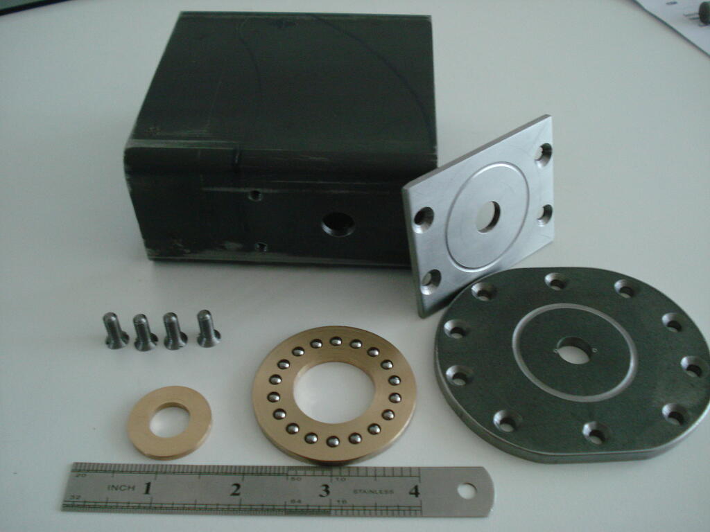
Then drew up the front Caster wheel design, sourced some rectangular thick box section steel and started on the axial bearing.
Took a slice of bronze off the 2" dia hollow bar after boring out to exactly 1" (25.4mm) first-
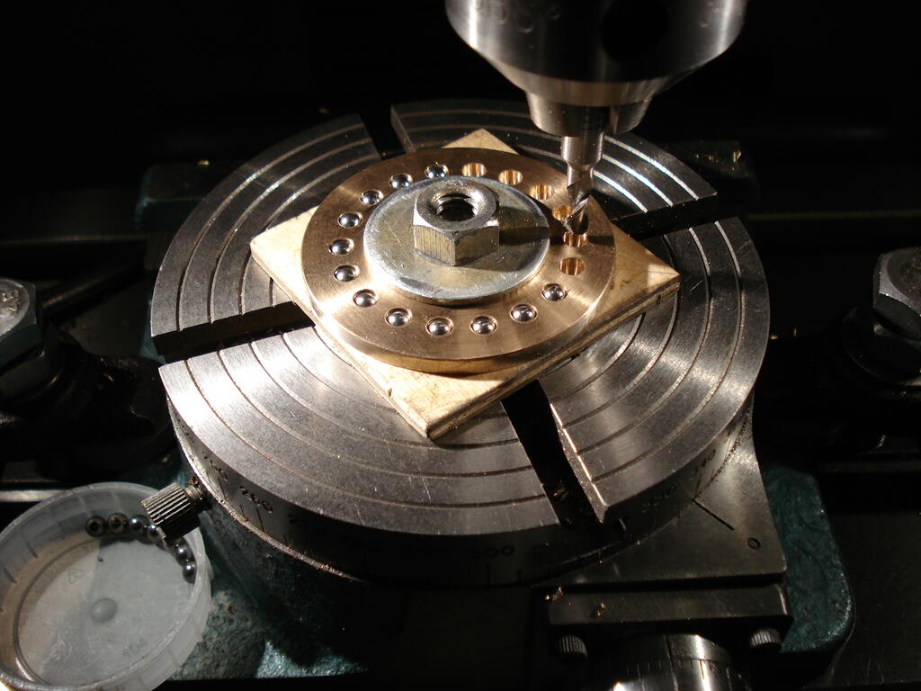
I planned to use 5/32" bearing balls from old bearing stock like I did with the Drill Project a few years back. Calculated the number required (18) and set up for machining on the rotary table.
As I was slot drilling through the cage plate, i had to use thin birch ply under it. Using a 'Ball Nosed Slot Drill' of the same diameter as the balls, they sit very comfortably in the respective positions-
I then machined a shallow 'race' in the 2 mating bearing plates using the same table settings, leaving running clearance on each side of the cage plate-
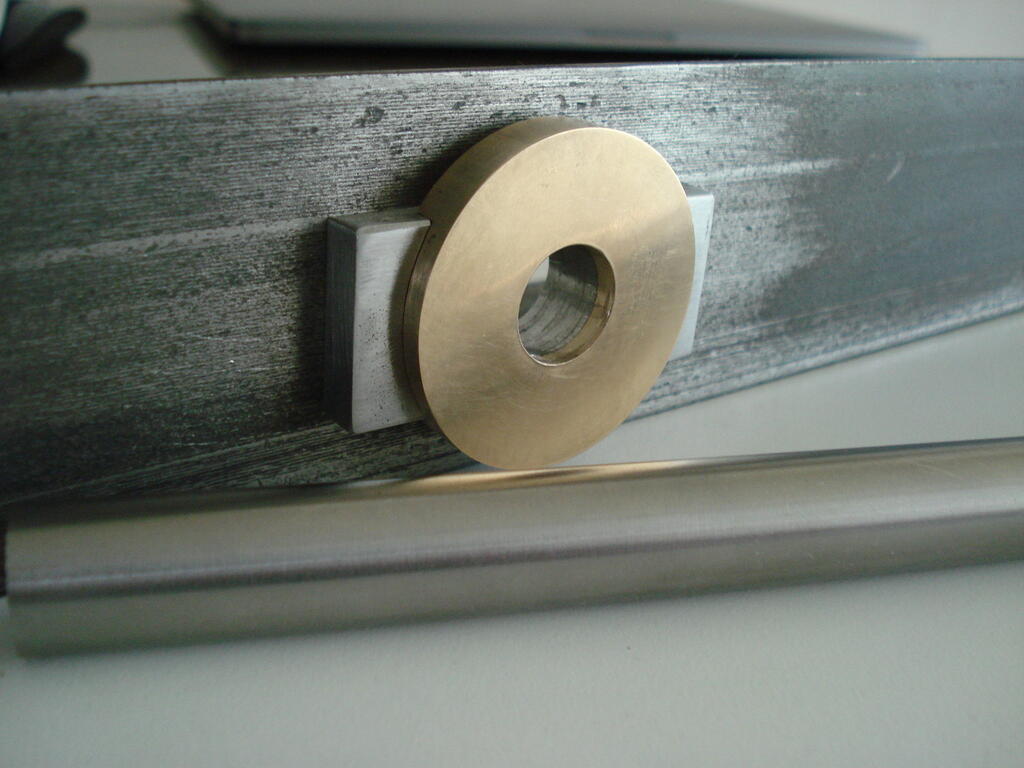
Very pleased with the way this bit went, being my first attempt at an Axial Bearing and it all runs very smoothly (without grease) when assembled.
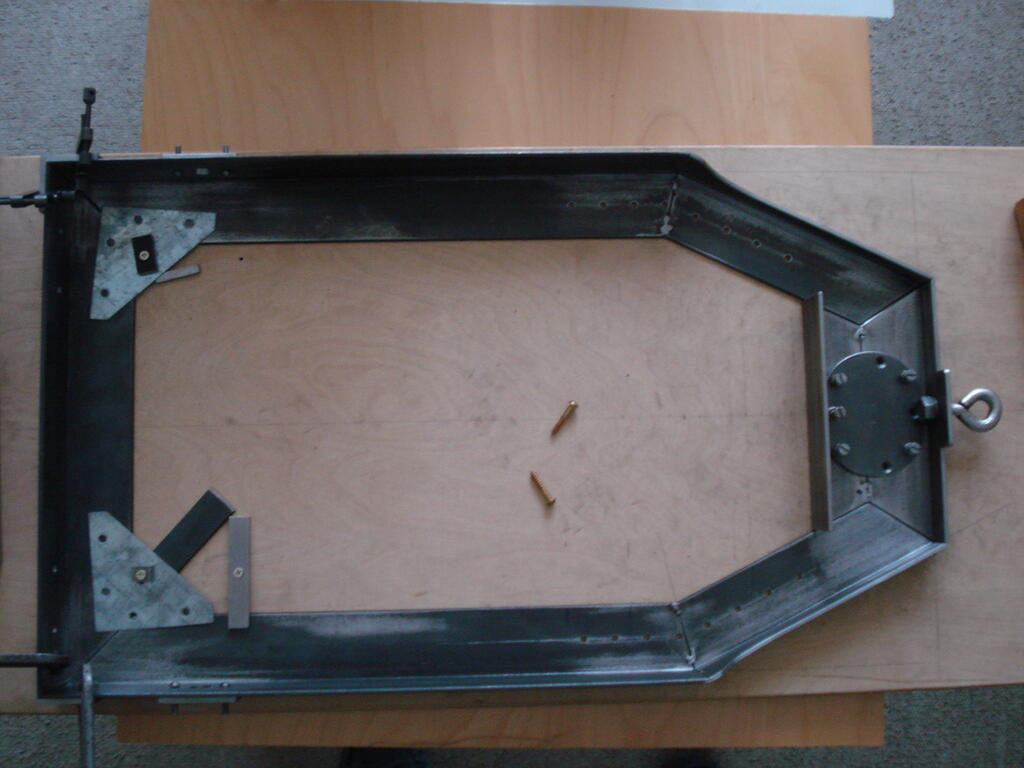
Been a while since the last post and have been occupied daily with this. Commenced work on the chassis after drawing it up, deciding on material sizes, ordering it etc etc and finally starting the cutting.
Settled for 50 x 50 x 3mm angle and drew the design up full size on a nice flat piece of thick birch ply. Chassis size is 360mm x 620mm.
After lots of sawing, filing and bending, I have reached this point -
Havng decided on three wheels, it took me a little longer to come up with the layout. The front wheel will be a 'Caster' type and it looks like I'll have to make it.
I've made a mounting plate 5mm thick to strengthen the area, plus a towing eye. I will tack weld all the joints and then decide whether I continue welding it all up myself, or get it done properly ! -
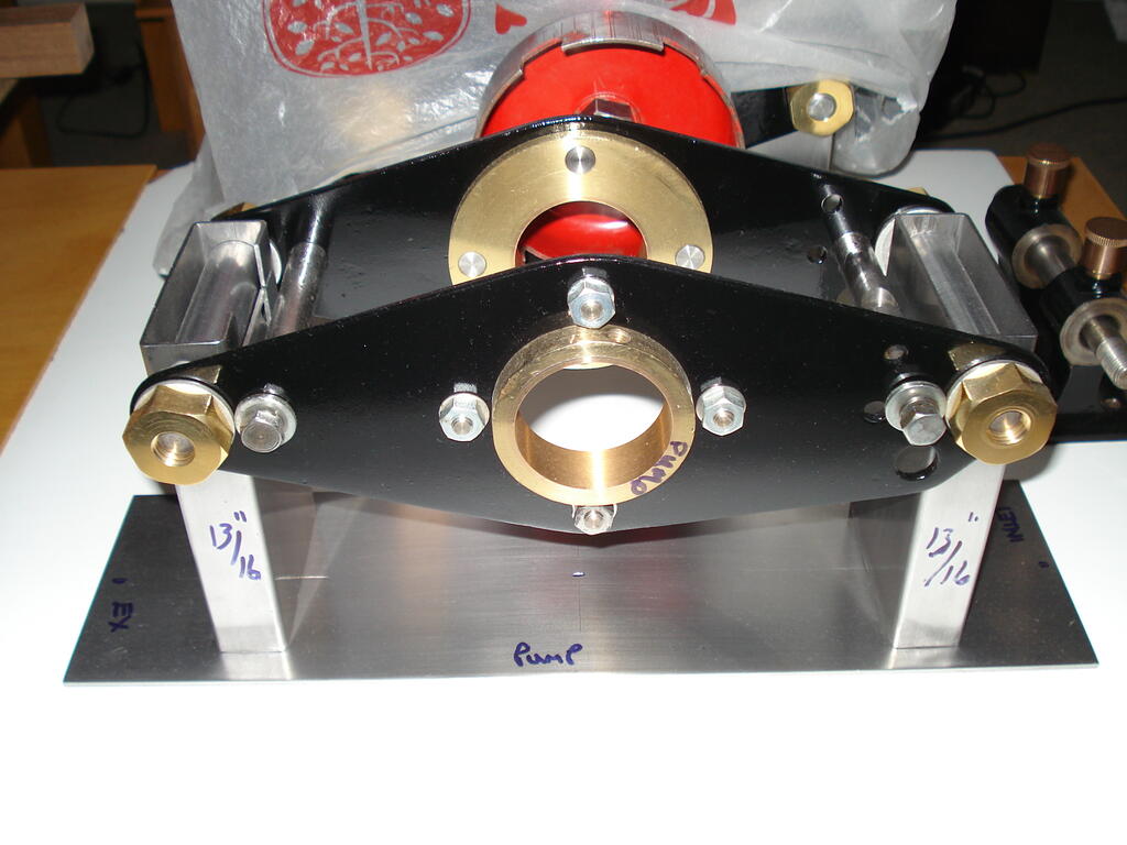
Back to engine and reduction gear mounts which need to be trimmed to final height before welding to the base plate etc -
Can't give you the belt size, but the part number from the manual is 2348. An online search for hayter 21 part number 2348 throws up several outlets to obtain one. Here's an example-
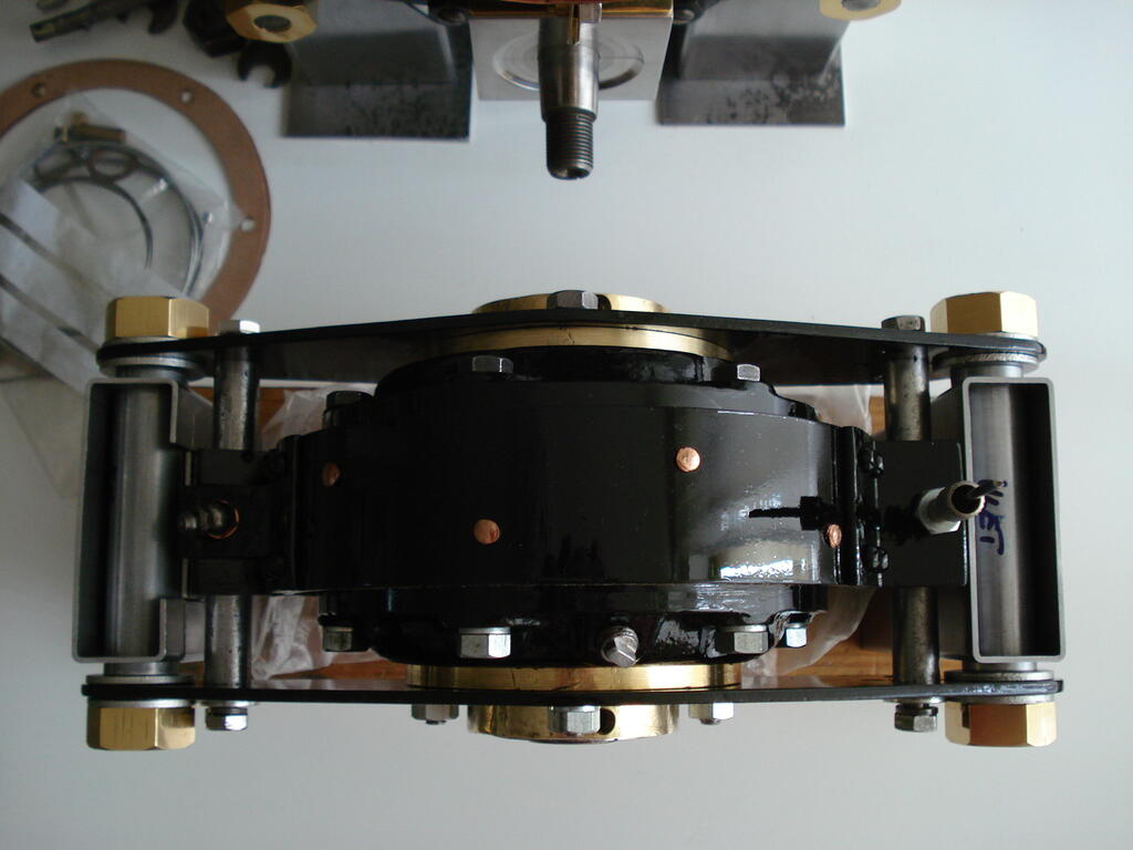
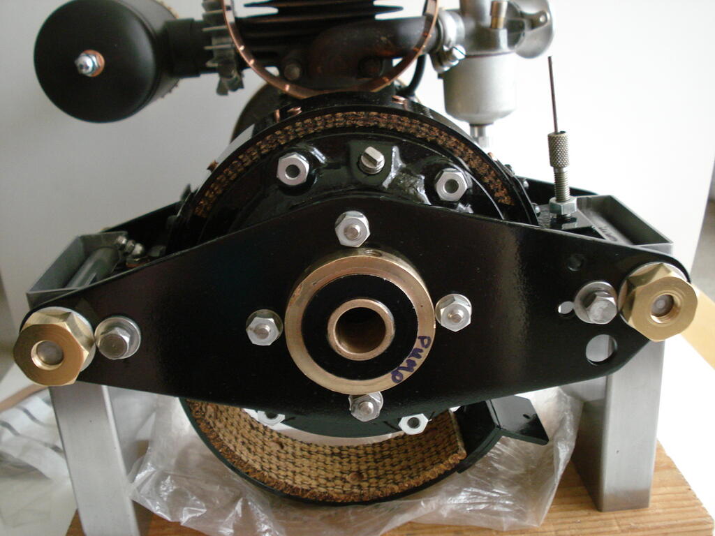
Reduction gear clutch parts finished now and all fit nicely in the finished bearing plates. Painted a nice shiney black enamel, it goes well with the polished brass parts-
Couple of jobs to do before I fit the innards to the Reduction unit, but able to move on to couplings and chassis design.
This is the nearest I can find online. This link - B&S LINKshould take you to the B&S website for Manuals and Parts LIsts.
You can either download and save directly or get them sent to you by email. The link shows User Manual (top) and Parts (bottom) Note - ignore the middle chinese one.
They cover variants of your engine, so look for your type.
In answer to your original question about the fitting/retention of the fuel valve, I can only suggest you replace the part. If it is the original plastic, then it wears out after 43 years.
It's below 10 cu inches, so model nbr is only 5 digits. The last digit will be an '8' which refers to the starting method (Vertical manual pull). If it was a 3, you would have a 110volt gear drive start!.
I'll get back on here when I've checked the Service Manual.
Afraid. there is still a problem with that first number. It cannot start with 224 on a B&S engine of 1980. a few pics of the numbers and the machine will help.
Hi Aldy, I can't make sense of the latest number you've posted. Briggs & Stratton have 3 sets of reference nbrs on an engine.
The first is the Model nbr (mostly 6 digits). It is based on type. Second is the Specification and lastly, as Lauren mentions, the serial number which is a 'Julien' build date code.
These numbers are stamped into the cowling edge with a label next to them (if still there)
We have to assume the engine is the original one fitted.
I suspect the engine will be about 4-5hp, so the model number should look like 130*** and will be above the previous 2 numbers you've posted (or to the left on a Vertical shaft engine)
Once we have the correct numbers and identified, I/we will be able to look up the type in the manual for parts and procedure for you.
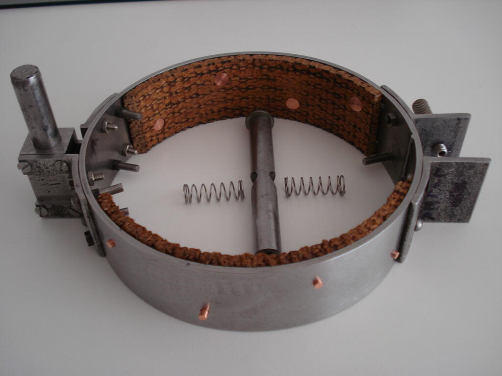
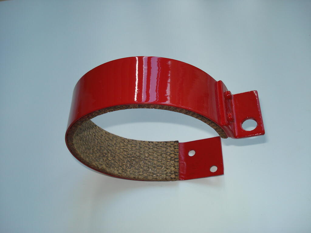
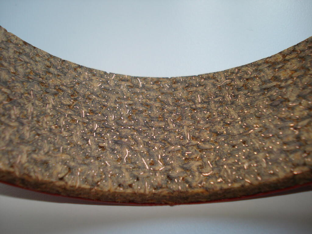
This part is very nearly ready for welding up and riveting now I've finished making the copper rivets and shaping the friction linings. Gives me 19.5 sq ins(126sq cms) of contact, so plenty of grip.
The bar with the springs will serve to keep the "Shoes' open and apply equal pressure when shoes are closed onto the PTO by 'over centre' lever lock and cable operation-
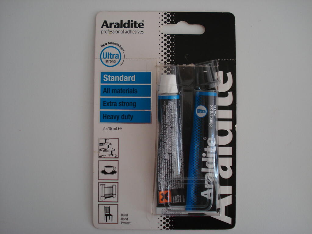
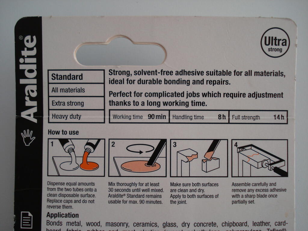
Hi Lauren, That is the 5min version. The deception is that they use the word original.
The one you want is the 'Standard' version. Gives you 80mins+ working time, but requires longer curing time setting-
I've used this brand for over 50 years and in hostile environments in excess temps of 65c and has held fast. There are other brands out there, but have never had a need to try them.
Providing the parts are meticulously clean, dry, sound and abraded for good keyed surfaces, it will do the job.
Always good to have an alternative source for friction linings.
I've used Auto & Industrial ltd for my requirements in the past. A link for reference - A&IFS Itd
I foolishly 'paid through the nose' for a TORO/Wheel Horse PTO plate (rivet on) many years ago....still in my stock!.
The 5min Araldite version is rubbish in my opinion. I always use the Original Araldite and has bonded my WH brake linings to spring steel with no issues. Just needs a longer curing time.-
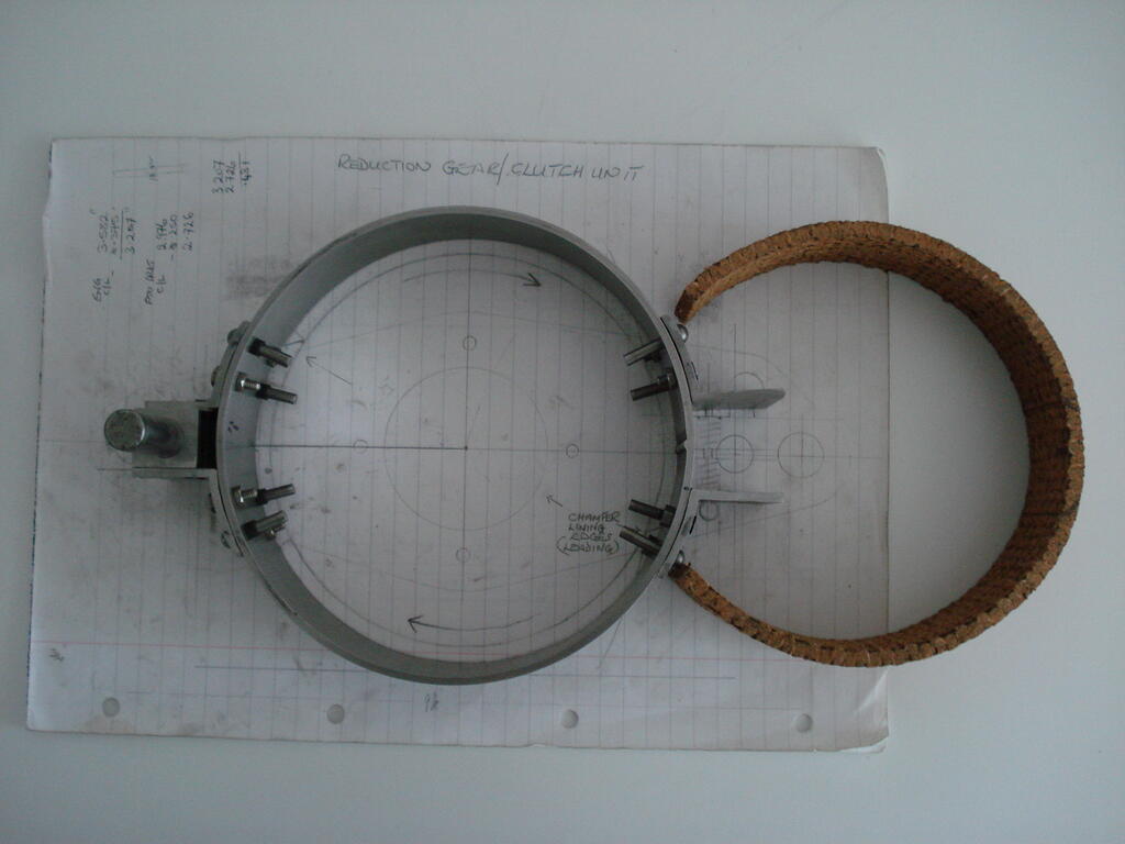
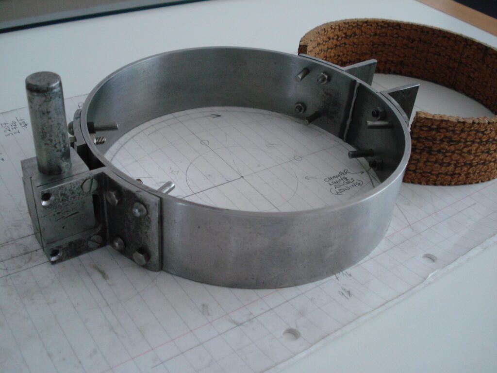
Thanks Mark, Hope all's well with you and family. Chassis plans are ongoing, yet to decide which species of wood to select....... meanwhile, I've been working on the 'clamshell style' clutch system design.
Details were mentioned in post nbr#10 on page 1. -
The steel ring is retained in the whole while I make and attach the various parts, then will cut it up when ready to close the 5/32" dia (4mm) rivets. Also then attach (copper rivets) the friction lining.
The 2 halves pivot on 1/2"dia (12.7mm) rod. the hinges are machined from solid and initially screwed together. Also welding them later before shaping. Quite pleased with the fit and no play in the hinge parts-
The bits of Angle plate were cold forged to shape with a hammer.
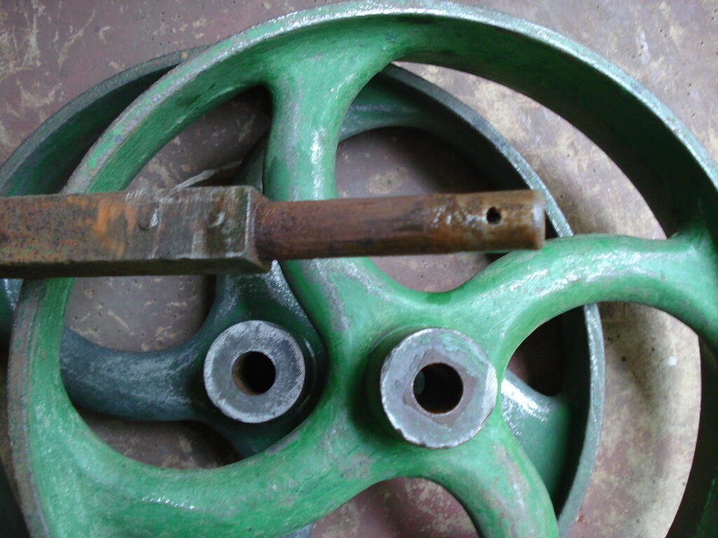
Another essential time saving part dropped into the stock for this project and although slightly large, they will suit the style of this project.
A pair of cast iron wheels were obtained, rust welded to an axle. Took a while to separate them and clean up-
These are just under 10 inches in dia (250mm approx) and are not 'handed', so the curved spokes will be opposite on each side.
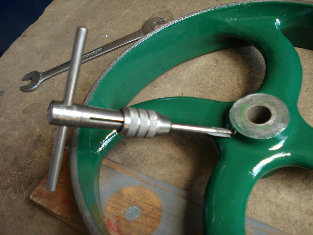
I found oil holes under the dirt and rust, so I've tapped them out to fit brass 'Oilers' -
The paint is the only colour I have in proper enamel, so not yet decidied the final colour. So a good price of a 'tenner' (UKL£10.00) secured these and save me a lot of work.
Afraid I can't. There were many versions of Onans used in Wheel Horses. Mid - late 70s BF type engines were used in some 'D' series models.
Mid -Late 80s in 'D' and '400' series.
Early 90s 'E' version engines used in 200 series tractors
Also 'P' version engines used in 600 series and others.
If you can narrow the field with quoting an engine spec etc and even the tractor info it is fitted to, an engine service manual for it may hold the key to solving the issue.
Hello, Welcome. First thing is, I know nothing about your machine. Secondly, I did a search for the model you specify and It throws up a fact that it should be powered by B&S 4hp 4stroke.
It's unlikely you will ever find a workshop manual for the machine for detailed servicing, other than a 'User' manual (another member here- Wristpin is the man who may have one?).
However, if you can give us a clue and confirm the engine type, it's model, spec and serial number, we should hopefully be able to resolve any issues you have.
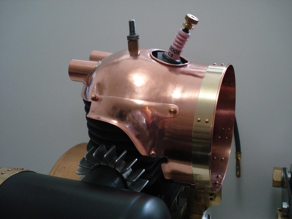
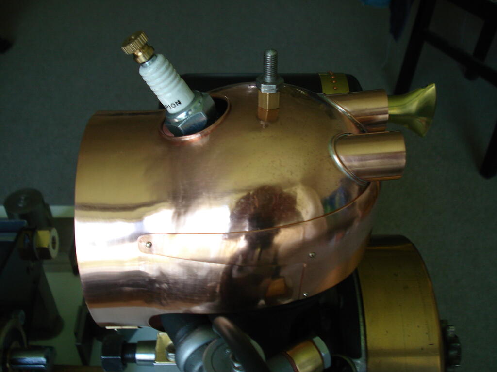
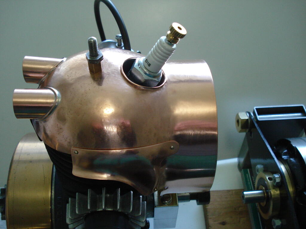
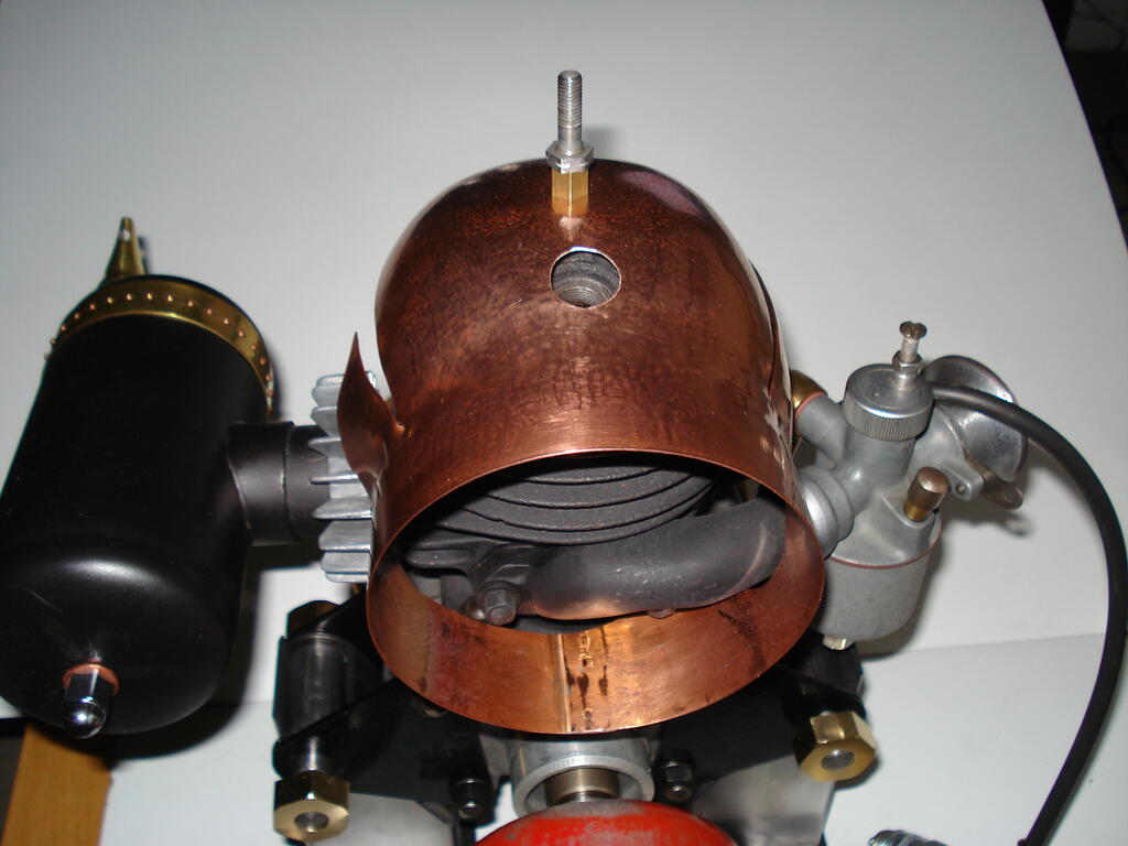
Just about finished the copperwork on the Cowling now which should now provide more efficient removal of heat and keep the intake side cooler-
Carb side additional shroud will be riveted on, as the full shroud can be fitted and removed ok. The plate on the exhaust side will have to be detachable.
Hi Nigel, Good to hear from you and hope all's well. Quite enjoy doing the beating of copper. Just about ready to stitch the cowl/plates together with rivets now that I've nearly sorted the Plug access hole-
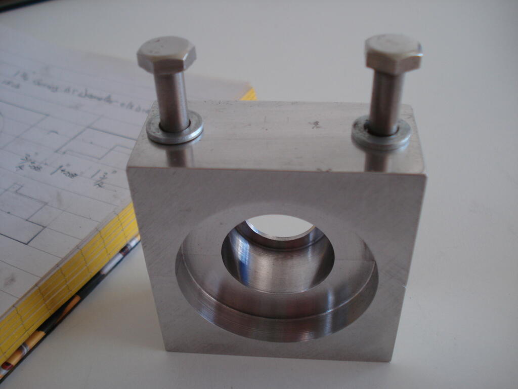
Meanwhile, I had to come up with a fixing point I'd mentioned to secure the lower part of the cowl.
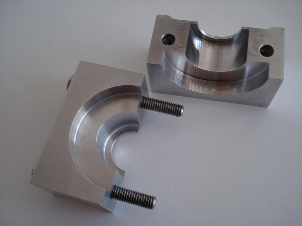
Decided on a split housing so that it can be easily assembled/removed. Machined 2 blocks of Duralumin to identical size, then drilled/tapped to bolt them together.
Excellent machining qualities of this metal made it a rather enjoyable job-
I was then able to machine the inner diameters to fit the flange it clamps to and clears the crank bearing and shaft by a few thousands of an inch (0.05mm).
It will also have a greased felt wiper washer inside to prevent dirt/water ingress-
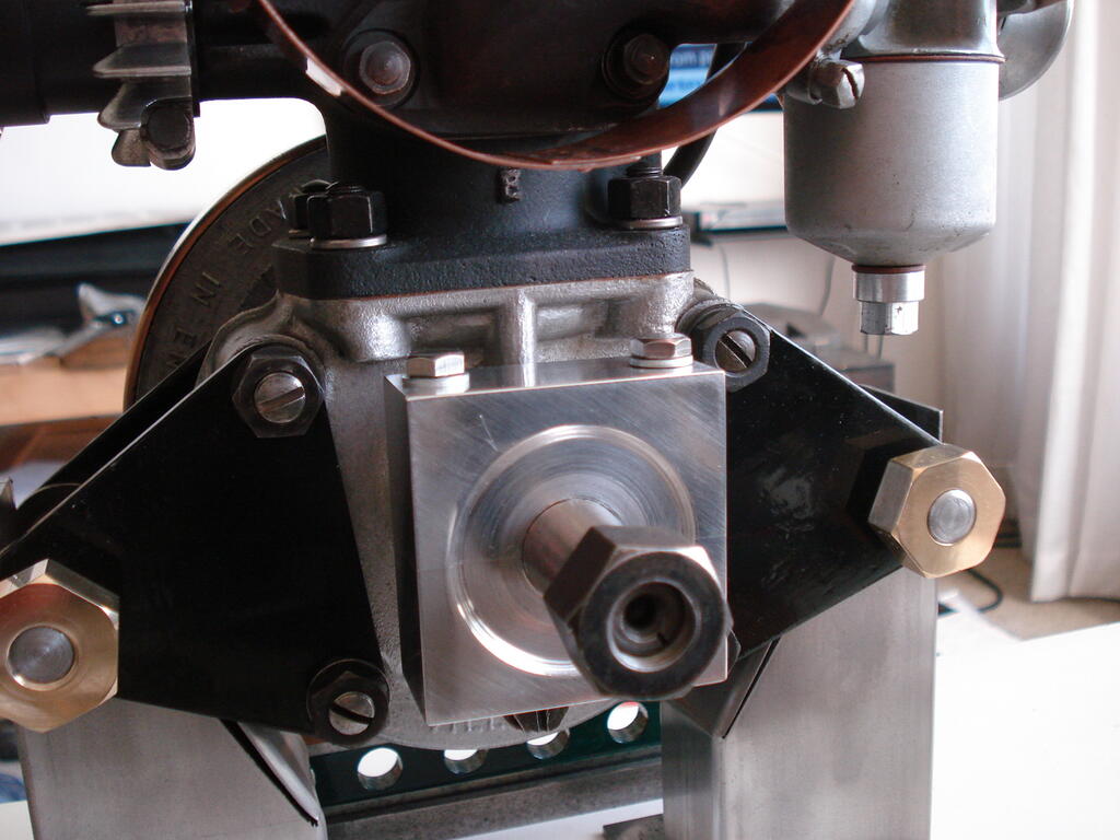
This now gives me a platform to fix the cowl and hold it securely-
Have lots of swarf to clean off the machines now!.
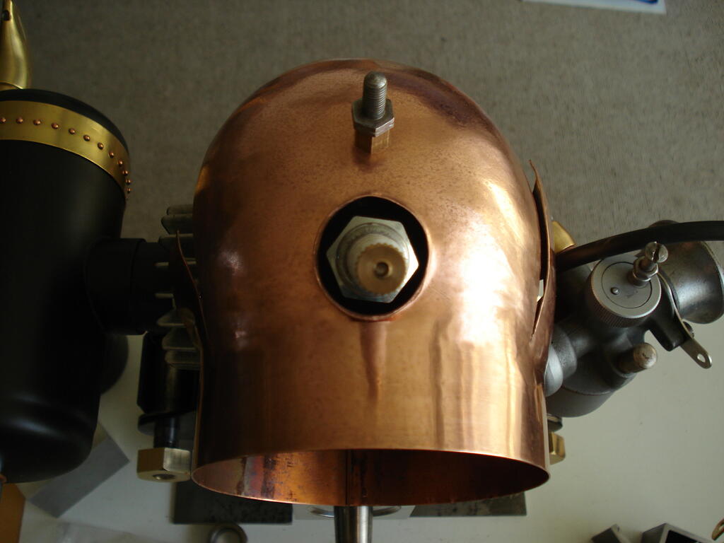
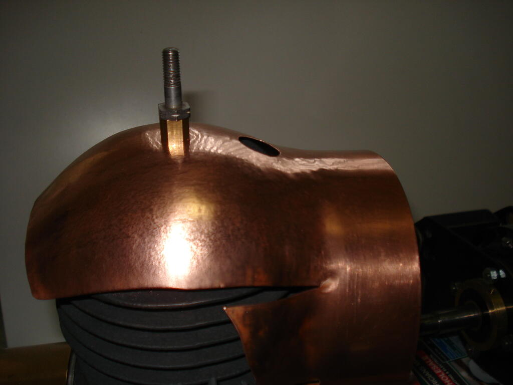
Bashing copper seems to be going ok so far. Part way through doming the top to fit the cylinder head. This is to utilise the 1/4"bsf threaded hole in the top to secure it-
There will also be a fixing that uses the flange of the crankcase at the shaft bearing output side -


 . Good job there with the panelwork. I expect it will work as good as it looks
Bits for my next Project
in Metal Shop
Posted
Had some lathe and milling machine time in recently. Started on the wheel for the front caster. Had barely enough 40mm dia EN8 Steel to make the hub and leave enough for the drive coupling.
Had to work really close to the chuck jaws, which was going fine with light feed, then I noticed the 'in-feed' movement of the parting tool went 'light' and easier !. I withdrew the tool and found it had failed !.
As I bought it in a modestly priced set 38 years ago and just lightly stoned the cutting edge now and again, it has served me very well-
I finished off with a narrow HSS type with no issues.
Indexed and drilled for the spokes on the Mill with barely 1.5mm clearance between rotary table wheel and chuck ! -
Also added an angled grease point and made the bronze bushes to be pressed in later-
I decided to keep the original engine output drive clutch bell and make a driven plate to replace the original Mower Clutch plates to form a coupling.
This would allow for any tiny misalignment of the engine and the reducton unit.
The load transfered through this part will be much less than it was orignally handling in a Mower, but I wanted it to be efficient and reliable.
Ordered a 105mm x 4mm laser cut mild Steel disc and meanwhile, I made 6 bronze wear pads -
The slitting saw used is only 0.0125" (0.3mm) thick. These pads were soldered to the dog spokes of the plate where they will contact the recesses in the clutch bell.
The plate was then set up to drill the 6 HT fixing screws to the boss-
Once I had cut the keyway in the boss, I pressed the plate with the drilled and countersunk holes onto the boss and finished fitting the screws. i need to file out the keyway in the plate to depth.
The bell drive recesses needed weld metal added where they were worn from mowing since 1954, but were not bad at all -
The caster wheel is at the final assembly stage. My reasons for using surplus thick walled steel tubing for the rim left over from my previous Water Cart wheel making becomes clear.
It all fits and allows me to re-use the wheel jig for accurate assembly ! -
Regards