-
All Activity
This stream auto-updates
- Earlier
-
-
The piece of spring steel arrived yesterday. I will let you know how I make out with it. Thank You..!!
-
Thank you John...
-
I'll get a piece out to you Yes that's the same but mine is a repop that I built a few years ago. $1500 + is too steep for little collectables. Here's a link of the thread.
-
-
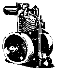
Hi John, Well my feeler gauge experiment was a failure. The material probably has too much tension. It would not prime and would not run, so I assume it is putting too much pressure on the ball. If you can send me a piece of the material that you used, I would sure appreciate it. I don't know if you are a fan of Bring a Trailer, but I visit the site occasionally to look at all the vintage cars, motorcycles, mini bikes and go kart of yesteryear. I saw this micro-power micro-bike. Is this the same type that you have or had? I posted a link below. https://bringatrailer.com/listing/micro-power-micro-bike/ Thanks, Bob
-
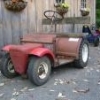
My Wife's Newest Addition (Duster/Fogger)
Wallfish replied to Mike in NC's topic in Ohlsson and Rice
The 20A engine is bigger than the Compact engines are but I'm not sure if the size of the fogger part itself is different. -
STOLEN TROJAN 'Toraktor'; My Trojan Toraktor circa 1957 is STILL MISSING. PLEASE keep an eye out for it when visiting shows etc this summer. I can identify it due to the mods I made when restoring it. Any info to: Tim@Permanden.co.uk Many Thanks. TCS.
-
-
Hi John, I made a spring out of a feeler gauge, but I have not installed it yet. I will try to get to it tomorrow or Saturday. If it does not work, I will take you up on your offer. Thanks, Bob
-
My Wife's Newest Addition (Duster/Fogger)
Mike in NC replied to Mike in NC's topic in Ohlsson and Rice
So they made them in different sizes? -
-
My Wife's Newest Addition (Duster/Fogger)
Wallfish replied to Mike in NC's topic in Ohlsson and Rice
Very Nice Find ! Not very many of those pop up for sale I have one with a 20A engine but not one of those smaller ones. -
Very nice setup. We have a powerhead but missing the tiller and the shaft.
-
-
-
-
-
-
Picked this up at a local show. I have seen one in person and pictures of another. The one said it was a Mity Moe Buffalo Turbine. The other one was painted and had no decals. Youtube Video
-
I have some blue tempered spring sheet metal .003" I can send you. I was making my own springs out of it and found that grinding the center out with a thin cut off wheel worked much better than trying to cut it out. Then cut the outside shape. Just don't grin hard to heat up the metal or it will loose it's spring properties. 50" x 3" can make A LOT of springs.
-
Hi John - Don't worry about it. I thought maybe you had a surplus of them. I will try making one from a feeler gauge. I have several laying around and will match up the tension and then cut it out and make the bends. I don't know if you have ever seen a video of the USPS letter sorting machines, but they have vertical rubber rollers that apply a lot of tension to the envelopes to keep them running at warp speed. It was not the whole spring that broke, just the very ends where they are cupped to rests on the diaphragm roller. That is what I found in the envelope. As I mentioned, it runs fine and may never be a problem, but it just kind of worries me that one of the legs does not sit on the diaphragm roller and that in turn makes the diaphragm arm sit a little bit off center. I will let you know how I make out. Thanks, Bob
-
Surprising that would break a spring. I pulled that one from one of my good carbs. I'd need to look around for another one if I even have one. . A while back I was making my own out of spring material sheet because they are pretty scarce now.
-
Hi John - I mentioned that the two legs of the diaphragm arm spring were shorter than they should have been, one more than the other. Well, I found two small pieces in the envelope that you sent the spring in. The culprit was probably the high speed sorting machines that the USPS uses. They put a lot of pressure on the envelopes when running through the sorting process.
-
Hi John - The diaphragm spring arrived today along with the diaphragm and gasket you included. Thank you for that. I installed it and got the Tiny Tiger 300 running. The one you sent is working but it appeared to be worn at the two ends, where it cups and should rest on the diaphragm roller. One side barely rested on the top of the roller and the other side was slightly shorter, so it does not make contact with the roller. I made sure that the spring was in as far as it could go. Like I said, it is working, but I don't know for how long. With one end of the spring sitting on top of the roller and the other not on the roller, it makes the diaphragm arm slightly off center, so I don't know how long it will run like that. I was wondering if you have another diaphragm spring, in good shape, that I can buy from you? Don't get me wrong, I am grateful for the one you sent, but would like to have a good spare in case this one does not last. I am more than happy to buy it. I mailed you $20.00 for the spring, diaphragm and gasket that I received today and you should have it by the end of the week. Thanks again, Bob
-
Thanks RIchard. As I said in my post I have the Spares/Instruction booklet but not the Clutch bulletin that I seem to remember reading about. Having thought about the problem overnight and understood more about what I was seeing with the chain cover off, I’ll answer my own question. Yes if you split and remove the primary chain, you will find that the clutch plates and sprocket with bonded friction material will slide off the axle. The rear plate is keyed onto the axle and watch out for the woodruff key which may fall out. I found having cleaned everything up and readjusted, and given some free play to the clutch cable when the clutch is engaged cable that I now have drive. What the booklet fails to mention (probably because it is just too obvious) is that you may need to readjust the free play in the clutch cable at the barrel adjuster having made an adjustment to the clutch leaf.
-
Good machine and well done for wanting to bring it back to life. All the help you'll ever need for it is on here with the O&R enthusiasts. I'm sure you're wise to it, but being a U.S machine, the Fuel ratio needs to be aligned with UK Fl oz and Gallon measures to produce the correct ratio. good luck. May be interested in knowing which Manuals you have. I volunteer for a Gardening Museum in Sussex, and we have many Mowers etc, some we may require detail for. Regards.
-

Hayter 21 Clutch adjustment
Anglo Traction replied to Baffle's topic in Pedestrian Operated Machines
There is a comprehensive topic on Hayter Osprey in the 'Other Garden Machines'. Link proved here- Also, look at the Home Page again and look down on the righthand side column to find 'Files'. At the bottom I've located a downloadable copy of the User Manual. See how you get on. -
-
Hello forum. I’ve been using a Hayter 21 I bought sold as seen in late 2024 regularly since last spring and I’m really pleased with it. It starts and runs reliably once I’d serviced the carb and ignition, and I get loads more cut in the same time I was putting in before, and dealing with far rougher areas too. I wondered if the power transfer to the wheels was as good as it could be, so I followed the service book to set up the clutch by setting the clutch leaf parallel with the machine body. Having done that there is no drive at all. Mine is a later model (1975 I think) with castellated nut and split pin on the near side rear axle. The castellated nut was only just being being held by the split pin and so I’ve now fitted a thick washer to take up the slack. So I guess this means that the clutch linings / clutch plate are worn out and I’ll need to dive in further. How do I get the clutch apart? I can split the primary chain - what / how would I do next? Additionally in places on various forums I’ve seen references to a Hayter clutch adjustment Service bulletin IIRC for 21s and Ospreys, but the link is to a Dropbox folder that is no longer active. Can anyone help with this? I have a PDF of the Osprey and 21 Instruction and Spare Parts book if anyone would like a copy DM me. thanks in advance for any help
-
It's on it's way
-
It's a check valve. Make sure you can blow through it in one direction (Flow direction). It may be clogged up from old 2 stroke oil. If it's clogged you can leave it off
-
Here's the photo @Wallfish Spark works fine. When I started cleaning the tank, paint flaked off, so I'm removing the rest and it'll get a new pain job. Found replacement fuel lines, and I'm adding a fuel filter for good measure. I'm leaving that small cylinder before the carburetor attached since I'm not sure what it is. I'll post pics when I'm finished.
-
I recently picked up a Ransomes Turf Trak 420 and can’t figure out how to diagnose the pro issue. The machine runs fine, but I’m not familiar enough with the front-mounted PTO system on these machines to know what I’m missing. Can’t get the mower to engage. Any assistance is greatly appreciated.
-
 Robby joined the community
-
Does anybody have a carburetor arm spring for a Tiny Tiger 300 that they would sell? Mine has one of the legs broken off. Thanks.....

