| |
-
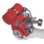
A bit more progress on the Tiny Tiger 400, I had to source or make the fixings for attaching the engine to the new base.
Here is a picture of the original fixings on the other Tiny Tiger I restored.
The screws are #10-32 and I found some with smaller heads locally. The acorn Pal-nuts are still made, but I couldn't find a supplier for the correct size, so I ended up ordering some modern ones, I will change them if I ever find a source of the correct ones.
The Tufnol/Paxalin tubes had to made using the one pictured above as a template. These were made from some Tufnol/Paxalin rod a couple at a time, using the nearest sized metric drill for the hole, then turned down to final size and finally parted off.
Cleaned up with edges with a file & sandpaper and gave them a coat of varnish. Two of the extra ones will find their way onto my Tiny Tor generator.
David
-
Did he not buy it then? I have noticed he hasn't been on here since the 8th of September.
-
-
That looks very nice.
I'm guessing these sold quite well over here as they appear for sale more often than any other O&R tool in the UK.
Most Little Wonders I've seen over here have had a hard life, not been looked after and can be pretty beat-up, occasionally one turns up that looks like it was left in the hedge to rot, also the plastic vent for the tank is often broken or missing too (it's probably not too hard to make something to replace it though). However there was a nice clean one on eBay Germany earlier this year.
David
-
I don't know if your still looking or bought the kit offered by Webhead, but there is a more reasonably priced kit on eBay at the moment;
http://www.ebay.com/itm/Ohlsson-Rice-Bicycle-Engine-/172904003458?rmvSB=true
David
-
If you post some pictures of your engine & details like the serial number/type stamped either side of the crankcase, we can probably work out what the power should be (it will be most likely 3/4HP or 0.85HP as it has the 10mm UY6 spark-plug).
Also don't forget to clean out the old filter foam from the air filter if you haven't already.
David
-
Webhead & Wallfish on here have new carb diaphragms for these engines.
David
-
The engine you have is a Type 133 engine made for the military, many of these keep turning up for sale, usually still in the original box never used, unfortunately I haven't found any reliable source of information for what the military used them for, that include the sites that mention Vietnam and the wrong info given on some sites mentioning WW2 (these engines didn't exist then).
The Type 133 engine has a tapered power output shaft, which is the wrong type for the bike kit gearbox which uses a clutch that fits the "D" shaped power output shaft.
You are most likely to find these kits on eBay if you keep looking on there, in fact there are three available at the moment, some of which have been on eBay for a long time.
Orline kit, missing tank, throttle cable & proper exhaust (it may be hard to find these parts), has best offer available;
http://www.ebay.com/itm/112536567748
Orline kit, missing tank and does not spark, a bit expensive but has best offer available;
http://www.ebay.com/itm/222581900155
Chicken Power branded kit with a bike you may not want, you could ask if they will sell the kit without the bike, also has best offer;
http://www.ebay.com/itm/322656615139
David
-
It's little more than clever marketing, the kit was originally sold by Orline using the less memorable name of "Bike Motor Kit" in the mid sixties, picture of the box side shown below (not mine).
A very similar looking kit was also available near the start of the production of the O&R engine in 1961.
Here is an advert from 1974 for the "Chicken Power" branded auxiliary engine kit, where they explain that it's gives the estimated power of about 650 chickens for your bike.
And here is the box side of the later "Chicken Power" branded auxiliary engine kit (also not mine).
And lastly here is an original TV commercial for the "Chicken Power" kit from the mid seventies on youtube;
David
-
It could be the crank seals leaking, as far as I know we haven't found a source for the original style ones, but they can be replaced with O-rings of the appropriate size (there are two different sizes of the crankshafts & bearings depending on the age of the engine).
The first two engines I worked on ran OK with leaky exhaust collector gaskets (I had no replacements at the time), but I now replace them as they usually leak after removing the cylinder.
I think I have at least one earlier engine that refuses to run properly despite being completely stripped and rebuilt.
David
-
As the base was missing I needed to make a new one, I had already found out the base was the same as the standard Tiny Tiger so I borrowed one from another in my collection to make a copy from. The original was aluminium, but I found a nice off-cut of stainless steel sheet almost the right width for the base, on one of the stalls at a vintage rally a few weeks ago.
After cutting to size and a lot of filing the new base was polished on one side & some temporary feet fitted (I think I may have found a UK source for some feet that look similar to the original ones, but need to confirm the size with the supplier).
David
-
The engine rebuild has mostly been completed.
New diaphragm, gasket & check valve fitted to the carb.
Starter repaired with new rope and missing wooden pull taken from the spares engine.
David
-
Hi Terry
The parts you are after are quite hard to find.
I guess something has reacted badly with the plastic of the coil to make it sticky, it may be possible to find to find something to coat it with or stabilise it, if the coil still works OK of coarse. I have seen this problem with earlier coils but I don't think I have one with that problem so can't experiment to find a solution.
Could you take some pictures of the damaged air filter, it may be possible the bend it back to make it usable. I have done this before as they are one of the most commonly missing parts and it can be very hard to find replacements.
I recommend you read the carb repair thread if you haven't done already.
Two stroke oils have improved considerably over the years since these engines were made, the recommended mix is 32 to 1, use a good quality AIR cooled two stroke oil. I have been using Stihl HP oil for mine.
Not sure it's possible to flush out these engines as dirt tends to get trapped in the crankcase section.
David
-
It will be similar to the one in this thread;
David
-
I'm still a little confused, did you service the carb?
You can check the carb primer works by attaching a short piece of fuel line to the inlet, put the open end of the fuel pipe in some fuel and see if it will pump fuel when pressing the primer button. If it doesn't pump fuel, check the ball isn't stuck to the valve seat (they can stick with dried out old oil) and that the diaphragm is in good condition (flexible with no cracks) if you haven't renewed it of coarse.
As for the tank, only one pipe goes to the bottom of the tank, that is the fuel pipe and has the filter, the other two pipes are bridged to prevent an airlock and are not for fuel to pass through.
You can check if they are blocked by part filling the tank and tilting it vertically (with something underneath to catch the fuel), cleaning can only really be done with fuel, try leaving some in it for a few days, or use or carb cleaner etc down the pipe.
If there is a lot of dirt in the bottom of the tank I also put some nuts in the tank with the fuel and shake it to dislodge the dirt. Pour out the contents and repeat if necessary.
David
-
Was it fitted with the base fuel tank? If so, there is a fine mesh filter inside at the bottom of the fuel pipe, the other two pipes are linked together (preventing an airlock at the opposite side to the filler). It could need cleaning or the fuel line maybe connected to the wrong pipe.
It should be possible to remove the screws without damage providing the screwdrivers fit properly, early engines used slotted head screws & later ones have Phillips head screws (Pozi-Driv screwdrivers are a poor fit and can damage Phillips screw-heads). They are sometimes replaced with whatever a previous owner could obtain or bodged with incorrect screws. Penetrating oil/fluid usually helps with anything tight or corroded as you mentioned.
David
-
Hi Todd,
It would be interesting to see pictures of the complete chainsaw, both your Orline Chainsaw-1 Model 103 & the Ford branded version above are updated versions of the earlier Orline Mustang chainsaw (I have the Sears branded version in my collection).
I really should look through my saved pictures and add pictures of all the versions I've seen to the forum, I haven't got any pictures of the Model 103 though but do have pictures of the Model 123 chainsaw.
13B 342 is actually the engine model & type, not the part number of the carb. No-one has yet found a source for replacement diaphragm arm rubber seals used in the late production engines, there is more info in this thread from earlier this year, with a possible solution that hasn't been tried out yet;
The only solution we have at the moment is to change out the bottom half of the diaphragm primer assembly & arm for the earlier ones that have the ball valve instead of the rubber seal.
Is the 'U' shaped diaphragm arm spring missing from your carb? I can't see it in the pictures.
Also don't forget to remove the old disintegrating air filter foam, as it can cause damage if it gets sucked into the engine.
Webhead and Wallfish on here have spare parts for these engines as well as the new diaphragms for the carb.
David
-
Here is a picture (which I'm sure I've posted before) showing the inside of the crankcase from a Turbair engine of mine that has ingested lots of the old filter in the past (not run by me), I should really investigate it further to see what condition the cylinder is in.
David
-
No damage will happen to the coil or condenser from using the brass strip stop switch, it simply shorts out the primary winding of the coil to the engine casing, the primary windings consist of a small amount of turns of thick wire. Magneto coils usually fail on the secondary (high tension) windings, which consist of a lot of turns of very fine wire, failure is usually due to water ingress/insulation breakdown or corrosion of the wire (fails open circuit).
Battery coils are a different matter all together, the primary windings can burn out if energised continuously.
Too much oil will result in a very smoky engine and would likely need the spark-plug cleaned more often.
O&R stopped recommending Outboard oil around 1964 to reduce the amount of carbon build up over time.
The thing to worry about with modern oil is the additives in some of them, TC-W3 (NMMA trademark) is a marine certification standard (although that doesn't mean you can't use it for non-marine applications), you would probably get good advice from someone with lots of experience at a garden machinery repair shop, instead of big chain auto/car stores (where the sales staff often know nothing about the stuff they sell).
The small bits of the filter foam can; get stuck in the feather valve preventing it from closing and cause premature wear/damage the bearings in the same way as dirt, grit or sand can. The oil in the fuel helps it stick to everything inside.
It all depends on how much of the old foam got sucked inside and how far it got, which is difficult to tell without further examination, I don't know if anyone on here has managed to clean the old foam out without disassembly.
I usually dissemble mine anyway, to make cleaning the parts easier, identify & replace any damaged or worn parts, renew gaskets and to clean & re-grease the bearings. I've not rebuilt any O&R's with a gearbox yet though, but there is a completely dissembled Chicken Power bike engine with gearbox still to do (was bought like that).
David
-
Here is a picture of my O&R display at the Peover Game Fair last weekend,
I didn't realise I had forgotten to put the base plate back on the Tiny Tiger until I unpacked it at the show, I took it off a while ago to make a copy from. Thankfully the forecast rain held off till I was back at home and everything was back inside.
David
-
Modern two stroke oils are much better than the oils that were available when these engines were made, mixing to the ratio on the starter decal with modern oils will result in a very smoky exhaust, using too little oil will result in dry bearings & premature wear.
Using a 32:1 mix of good quality AIR cooled two stroke oil should be good, I have been using Stihl HP oil (for all my two stroke engines) which was recommended by someone I know that uses two stroke chainsaws regularly.
Both outboard oil & #30 SAE oil (the modern equivalent is NOT suitable due to the additives used) have been mentioned in instructions for these engines over the years.
David
-
For long term storage draining the tank & running till all fuel is gone was recommended in the winterising procedure.
There are two ways to stop the O&R engine, one is the brass stop switch on the back of the magneto plate (exhaust side) or a remote stop switch (used on some tools), both of these short-out the primary of the magneto. The second method is to close the choke (as you mentioned). On early engines there was an optional third method, a shorting strip for the top of the spark-plug, shorting the spark-plug can be used if other methods of stopping an engine have failed (usually with a well insulated screwdriver).
Here is a picture of the brass stop switch,
And the (optional) HT shorting strip on an early engine,
David
-
Hi Zak
You could start a new thread, or add to a relevant existing one and we can help with any other questions you may have.
The Compact engines were of course designed as a small industrial engine to be used for powering all sorts of portable tools, but were also used for powering (and still are) models.
David
-
You may be best using clean fuel then, as I've never tried carb cleaner I don't know what it can damage (certainly some electronic & switch cleaner sprays can damage plastics or cause other problems with vintage electronics).
Be careful the power output shaft doesn't slide out & let the tiny bearing rollers fall out, if you take the induction housing apart and nothing is attached to it.
The only adjustment for the timing is the contact breaker gap (should be listed on the starter decal along with the spark plug gap). The flywheel position is fixed with a key.
David
-
The TAS Motor (Tanaka) does look to have copied some features of the Ohlsson & Rice Compact engine, I'm not sure if your drill has the P5 or P7 engine, there doesn't seem to be much info on these on the web, even Hitachi Power Tools (they acquired Tanaka in 2007) don't have any manuals going back that far on their website. They do claim they "Introduced the world’s smallest industrial general-purpose two-cycle engine- P7 (22cc)" in 1962, the O&R Compact engine dates back to at least 1961 (1.26 Cubic Inches or approx 20.65cc).
http://www.hitachipowertools.com/us/main-navigation/tanaka-history
The history mentions that Villiers (misspelt Villers on their website) had a licensing agreement to manufacture the P7 engine.
Also your drill isn't exactly the same as the other Tanaka drill on here;
David
|
|