| |
-
From what you have described to this point, you have covered just about all that should have sorted the issue.
I would never criticise anyone for doing things their own way, only offer advice on the assumption a person is not familiar when they ask, but it is hard to know people's situation.
The standard to which you have reassembled/described will result in an engine that should run effectively, based on what condition you described it in initially after the Head was off.
Short of what You/Nigel suggests regarding the possible shearing of the Flywheel Key, the only things it can be are the Fuel Pump/lack of fuel or the iffy Aftermarket Carb!.
As you have another C-161, if that is running fine, then I would carefully remove that Carb off it and bolt it onto this problem engine without affecting any Needle settings.
If it runs ok, then your new Carb is suspect!. Keep at it, you'll get there, and be all the wiser for it.
-
I had wondered just what procedures you have followed/applied to reassemble the engine and having seen that your still having smooth running issues, then there are just 2 basic things that are affecting it. Ignition or Fuel.
Ignition- It is always best to set the 'Static Timing' , as just sticking a 0.020" Feeler Gauge into the points is insufficient.
Just for curiosity, I did set my points to 20thou and then check where the Spark was occurring and it was virtually on the TDC !!.
Just doing the points does not compensate for Breaker Rod, Points or Cam Lobe wear and 20thou is a default setting.
These are the marks you should find on the Flywheel periphery -
They are viewed through a small hole in the Shroud similar to this example on a K301-
A simple process and when I had set my engines to this method, the whole running performance and even the sound of the engines changed for the better.
Having changed out virtually all of the Ignition parts, other than timing it properly, the only other main problem area is the Carb.
Just to be sure you have the correct Carb fitted to it, could you post the number stamped in on the Flange and if possible look for the number 'cast in' inside the Venturi throat (where the Main High Speed needle passes through the bore). It should be '30'.
I say this because someone may have bolted a non original one on it.
A worn Throttle Shaft will drastically affect the running of an engine and it/yours may be badly worn.
If it rocks back and forwards in it's bore, then it's worn.
There are loads of small capillary and galleries inside the Carb and Needles that may not be clear of detritus, even after what id deemed as a good clean, so it is possible there is still a blockage.
Depending on what brand and type of Carb you have, depends on what 'Preliminary' needle settings you need for setting it up, prior to final adjustment on a warmed up and high/low speed running engine.
So once you've sorted the timing, we can move on to the Carb issues.
As for parts, I've used Meetens for over 35 years and so Paul Childs should provide all you need (usual disclaimer).
You will need to obtain the part numbers for them, so if you need any help let us know on here by posting your K341's Engine Spec and serial number on here.
-
Suspect that is the ACR (Auto Compression Release)?, it occurs when the Piston is approx 1/3 up the compression/firing stroke travel. It should lift the Exhaust Valve between 0.030" and 0.042" briefly to reduce the start up load on the Starter Motor and gear teeth. The ACR cuts out when the engine reaches about 600rpm.
-
I may not be the best to offer advice, as I tend to do things in a meticulous manor when it comes to engines.
Depending on whether you wish to have a good condition running K341 or just run it into the ground with the minimal of expense (I suspect the former),
the best way to proceed is to pull the Cylinder Head (it may have never been off and totally coked up).
You will visibly learn all that may be wrong with it in the 'Top End' and Cylinder and the cost may only be a few hours work and a New Head Gasket.
I don't know your Skill/Experience levels, but unless the Valves/Rings/Carb wear condition is ok, you can play around forever trying to get an Engine to run correctly/properly.
Certainly sounds like your Rings are worn and/or possibly the Valve Guides, as they should run with a vacuum in the Crankcase or it will blow the Seals.
They are good powerful engines, not prolific either. Well worth a proper rebuild.
-
You're correct of course!.
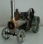
These were used to start the testing of Avon Engines fitted to a Hawker Hunter pre production Prototype F1 at Dunsfold in the year Date Stamped in the base of the Cartridges.
I also have 2 shell cases from the testing of the 4 x 30mm Aden Cannon Packs fitted to them. I'll try and find a similar use for them on this project as well.
Received a lump of hollow Phosphor Bronze today, 2" dia x 4" so I can machine/refurbish the Big Brass bearings using an insert-
Pressed the new bushes into the PTO Lump and made one up to fit where there wasn't one originally to improve the running clearance limits.
A quick assembly to test it showed much smoother drive transfer. Still a bit more machining to do on the PTO before it is ready.
Having trouble sourcing some materials still, need some Cast Iron to make 2 Flexible Drive Yokes (Engine to PTO).
Don't want to import some readymade (nearly) from U.S. if I can help it.
Also need 60cm x 30mm x 0.5mm (0.020") Spring Steel for the Brake Band. All of this stuff I had years ago .
Sure you all know the 'Moral' to that story !.
Anybody done Metal Spinning on a Myford ?. Look's like I'll need to have a go .
-
Bit late but Happy Birthday Norm !. Wish you many more to enjoy..........Good to hear your having your Cake and eating it .
-
Thanks Gents, I'll try and maintain the standard you guys set. Here's a few pics, in between some waffle, 'cause I know you like pics.
Spent some time over the weekend sorting the PTO 'Lump'. Need to take out the wear and as much slack in the meshing bits as possible.
Have given it a clean up and inspection, ordered 1/4" x 2. 1/2" HT BSF bolts (New old stock) and a Plain Oilite bushing.
Had a battle to remove the large bushing without a press, so had to improvise with a long bolt, various spacers and elbow grease-
... got there in the end-
Fortunately I had a big enough lump to machine the Flanged Bushing from. The other side was a bit easier to remove being a Plain Bronze bushing-
First operation was boring and turn the press fit diameter, then reverse to machine the Flange and thrust end to size-
Managed to finish the bushing to a good fit in both axial and radial sizes to remove the wear, so should last a while-
Also cleaned up the Line Shaft Bearing mounting ready for paint. Had to machine the base flat after a clean up. A 5/8" reamer went through ok with slight resistance,
so has little wear (un bushed), but not a well machined bore . May bore it out to 3/4" and press some bushes in.
Grease Cups were washed out and had a pickle session in White Wine Vinegar. Polished up nice inside and out-
Lastly for now, These 2 identical items are going to be the Fuel Tank(s) in tandem with Balance pipes and Fuel Level Tube-
These have a bit of history and are from my 'Late' Father's career and so I'll put them to use.
Anyone know or care to offer their idea of what they were used for/on ?. Dimensions are- 72mm dia at the open end, and 167mm in height.
Bye for now.
-
A real shame things have to happen this way. I treasure and use the Tools and things that belonged to my Father.
Hope they end up going to the likes of people on here to continue their usefulness, rather than for them to be junked.
-
Wasn't sure where to locate this, so as it will be 95% Metal, here's as good 'a' place as any.
Wanted to use the spare Villiers Mk2 Midget Engine I am rebuilding to power something stationary?, but will also need to have additional cooling.
I've been thinking about what I already have laying around in parts n materials I may need and started digging them out from various storage places.
Blowing the Cobwebs from my memory, I recalled back in the early 90s salvaging some parts from a 1948 Ransomes Simms & Jeffries Lawnmower, namely 2 hefty brass bearings in Plates that carry a heavy lump of (rusty) cast iron that acted as a PTO Clutch, rpm increase Gear Box and stored a lot of inertia.
The Mower itself was way past fixing up. Shame, as it had a large Starter Hand Crank, the likes of which I have never seen anywhere since. Anyway, I managed to recall where they were.
There's 2 remote Screw Capped Oilers, an old Line Shaft Bearing block (5/8" bore) with Brass Screw Down Greasers. Length of Box section Steel and 15/16" AF high Carbon Steel.
Also dug out some stubs of 1" and 5/8" AF Brass from my Garage Door Counter weights which turned out to carry several other useful bits.
Previous owner/resident of my property (60s/70s) must have been a Turner judging by the very dusty tarnished evidence-
The inside of this PTO Clutch is similar to a Diff which spins freely when drive is not engaged. A large Brake Band clamps the outer surface and the planet gears inside transfer the drive to the opposite shaft at a 5:1 increase in RPM. I plan for it to act as a speed reduction unit and PTO Clutch.
Condition inside is fairly good, considering there was water amongst the old grease.
I need to make new heavy bushings, fit new bolts and machine the outer friction face which is pitted, but still has the 'Witness' and number marks Stamped in by the guy who first assembled/finished it-
.
My main intention on this project is to refresh my limited familiarity with Lathe and metalwork practices on a fair amount of old Brass, Copper, Bronze and Steel parts. I'll be using BSF, Whitworth and BSP thread forms , and I won't be in any particular hurry to finish it, so please bear with me, as even I don't know what it is to look like yet! .
-
Very nice Items Alan and a good teaser Thread.
Just guessing with the Square, but wonder if it's for checking/setting bent tubing of a fixed diameter to 90 degrees?.
The Dial Indicator is superb. I love these little precision Tools/Instruments.
Reckon It is used for centring round bar or tube stock in a 4 jaw Chuck, either on the circumference, or setting the rounded Ball end in a previously centre drilled end or bore.
As for the last item, I think Norm is on the ball with a Plunger type Tool. and hope he solves it for us.
I can't be sure from the pics, but wonder if it has included angles of both 55deg and 60 degrees ?. If so, maybe it is for checking threads in some way?.
If not, maybe for checking the 'Lead' angle of Worm Drive Gears or something?.
What I can't see, is how a measurement can be taken with the instrument/tool just held in the hand, unless there is a 'Stop' or register on it that provides consistency of measurement.
Edit- 4pm local. It is as Koen said (missed his link) and Norm vaguely recalls. It's a rev counter....had me stumped!.
-
From what I have read, learned and tested over the years of using this process, the best Battery Charger set up is to have an older type Charger that has no 'Auto Reduction' or Cut Out.
4 Amps is about ideal, but I've obtained good results with 2.5 amps (or less) and used an Auto Reduction Charger . It just takes longer to do it's job on large pieces/panels.
Power/efficiency reduces with build up of corrosion on the Anode Rod(s) and resistance increases ,so you can work with what you have if you clean the Rods regularly and keep the gap between Anode and the Work piece to a reasonably close position.
A handy method I use is to have 2 sets of Anode Rods. I use one set then switch them over, but use the process to clean the old Rods, saves a lot of cleaning.
-
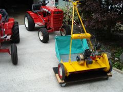
As Darren says re the Tag. The 147cc Villiers (mk15) was introduced after Dec 1953, there is also an HS version that produced 2.5bhp and had a conversion kit available for running on Paraffin (Kerosene).
If the Grass Box is original to that Mower, the 'By Appointment' transfer will refer to H M Queen (Liz II) .
The Handlebar Style is also a giveaway that tells us it is fairly modern (post WW11) in Atco history.
It looks unmolested, so the Tag should still be there somewhere and these were used during the 50's.
Another way to get a rough age on some Villiers is to inspect the Flywheel for a date stamp. This may narrow down the date a bit further, but bear in mind that Villiers 'Stock Piled' manufactured parts and so a 1953 stamped Flywheel could be on a 1955 built engine.
You can get the manuals for the engine.
-
Ok, If it is an Osprey and 7hp, then I can offer you some help. The Engine Model, Spec and Serial nbrs on the Engine (1980) in my original Thread is 170702 - 5638-01.
If you want to check further, then just count the number of Cylinder Head Bolts. If you have 9, then it should be 17cu inch 7hp............... A 5hp (14 cu in) engine has 8.
I have PDF Files of both the Illustrated Parts Manual and User Manual that I can post here or send. Or, you can enter the numbers into the Briggs and Stratton Website Manuals section and download your own.
The User Manual has most of the common service procedures and Data you'll need.
Any other bits you need, I can check my Manual for you.
-
Great story. They don't end better than that eh !.
-
Surprised to see this old thread resurrected, but obviously served it's purpose as a reference as well.
But of a challenge Rog, trying to ID the engine in that example. The Shroud look's like it has been replaced, along with the rewind starter.
Problem is that the Engine numbers are stamped on the side of the (non original) Shroud.
Engines in these machines of this age (70s), I believe were either 5 or 7 hp.
I would need more/better images of the engine with any numbers you find. I have a workshop Manual that covers all Briggs up to 1982.
Before the No Spark issue is further investigated, check you are trying to start it with the Throttle at mid position.
There is a 'Kill System' that cuts the ignition at 'Throttle Closed' position.
Note also that if the machine is laid on it's (carburettor) side, the Crankcase Oil will flow into the Carb and subsequently the upper cylinder/Exhaust and Air Filter via the 'Breather'.
I can't be sure yet, but I don't think it has the 'Magna- Matic' system.
Suspect though, it may possibly have and just need a good clean and service of the ignition system, i.e. points, condenser and Armature Air Gap checked.
-
Ah, now I see the Engine, it may only have a Single SU or Zenith Downdraught under that Filter. Forgot that it's likely to be a Series III .
-
Don't think my spares will fit Norm. Not easy to see what size it is, but look's 1/4" BSP?.
-
Glad to see you released it from storage and got it to yours.
Assuming the Floor/Chassis is good, there is nothing that can't be fabricated on it. Superb project.
I remember seeing these in the very early sixties. If your able, I would like to see an 'Under Bonnet' shot, and there should be nice pair of SUs bolted to the straight 6.
Thanks for sharing.
-
From the album: Anglo's Images
Running in time to bed the new Piston, Rings and small end. First Drivetrain test is real smooth and quiet
© RCS2015
-
I take no credit for the ingenuity of the attachment, as it was conceived more than half a century ago by renowned Model Engineers in this form .
I just adapted it to my use/machine and so posting it on here, it will inspire others to apply a principle to fit their needs.
Reckon looking back into the past can solve many problems we come across, as probably like for example Norm's Dad and mine, a lot can disappear with them .
-
Maybe it's the same as a Full refurb on a Garden Tractor (without an engine Hoist), or a hard starting Kohler with a Pulstart
-
Look's like a Slide Weight from an Exercise Machine? . So what is the total addition weight of it Norm?.
-
Bit limited until I get the new Glasses, but I decided to make a Classic/Vintage looking replacement Spark Plug Screw Cap.
Regretfully, I had to make it to fit a modern Metric threaded Plug .
I made an Indexing tool a long time ago that allowed me to make and Mark Out a lot of parts for my Traction Engine.
It just bolts onto the Change Wheel Quadrant (Myford ML7) and a Mandrel that fits/locks into the end of the Spindle to carry any number toothed Change Wheel.
For this job. I only needed to use the 25 toothed Spindle Driven Gear (removed the Tumbler Reverse selector Lever and Stud)-
Stub of 1/2" dia Brass turned down to shape, drilled and tapped M4 . I used a 60 deg pointed lathe tool on it's side set on the C/Line and proceeded to manually pass the Tool across the face taking small light cuts to 20thou deep, then turned and locked the Lathe Spindle with the pointed screw in the next tooth groove and repeated. In progress and prior to Parting Off from the Stub-
. The result is a nice clean grooved rim to grip with the fingers for tightening on the Spark Plug.
I do have Knurling Wheels so I can make a Clamp type Knurling Tool, but preferred the straight grooves for this job.
I'll make a BA Threaded one as well for when I find a good genuine vintage Lodge CB3 Plug for the Villiers.
-
That's one nice project you have there!. (insert Envy Smiley here). 1959, London registered 6/90. Interior is as you say......real good.
I had an Eye Test for new glasses today, but do I see 58474 miles on the Clock?.
Shame all the Dross on top creased the roof, still, at least it wasn't thrown inside it.
Yeah, I also remember Green Shield Stamps.
Look forward to following your progress on it.
-
Ah, ok. 1-0310 is listed (U.S.) as a '71' 12hp with a Kohler Engine in most WH records.
So you have a Belgium-ised Model that used up surplus parts from U.S. for the Euro market.
Not big deal really, as it is converted to what it should have been, albeit with a later engine.....so call it a Raider 12 and get some new Decals for it
|
|