| |
-
Looking forward to seeing the progress Alan !. I've got plenty of bite marks on my Lip from about a year of anticipation.
-
I use these people to obtain Friction Lining materials- if it helps you- -LINK-
As for parts Manuals etc, if you look at Wristpin's post half way down PAGE 1 of this thread, you will see links to Dropbox files.
Regards
-
What size of Ball is required?. I have an assortment of fractional inch sizes in Steel, Stainless and Phosphor Bronze, all precision finished. Size range from 1/16" to about 5/16" I think....some bigger. If I have what you need, I can help you.
-
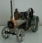
Apologies for resurrecting an old thread but I noticed the high volume of views and that I failed to add a pic of the finished Mower sorry!.
Here is one I meant to add just after it was finished (along with other Reprobate Refurbs)-
It looks like I'll be able to pull it's covers off and give it a run soon, so I'll try a Vid a working session.
And just to add more detail to the recorded history of this Mower's life, my friend Roly (son of original owner) recently sent me some pics he found of him using the Mower when he was about 9yrs back in the early sixties-
Regards.
-
Nice work Darren. Like you, I've done the same with the surplus Villiers Midget Mk2 parts. Hoping to get back to doing things with it in the workshop soon.
-
Hello Riber3, welcome to the Forum. Firstly, you can test the Armature/Coil using the advice on the B&S site- -LINK- .
As far as I'm aware, the HT Lead is fixed to the Coil and sold as a complete unit. Part number for the Armature on your engine is 298968 and are about UK£33.00. for a genuine replacement.
Other things to check are the 'Kill' or 'Ignition Ground/Earth Wire' and setting. The linkage may not be isolating this when the Throttle Lever is moved to start position.
Some people have converted to a Transitorised Electronic Ignition system to replace the old system, where I'm sure someone on here would assist you with what is needed.
If you prefer to stay with the original system, then it is also possible the Condenser may be faulty.
As for Manuals etc for your engine model, if you click on this link, it will take you directly to B&S site's manuals for it. - B&S 170700 .
Hope this helps.
Regards
-
Good progress Ian, like the Suds Pump Setup. As for the Motor, like Norm says, it's a very reliable brand, but pretty powerful for your needs.
I just checked the Start and Run Current draw for it, which will be in the region of 33 Amps and 16 Amps respectively!!.
If your supply Amperage is questionable i.e 20 Amp Ring Main, then you may well find it tripping out on start up?. For your Lathe size a 1.5 Hp motor would be more than adequate and more economical to run with minimal risk of tripping drawing roughly 20 Amp Start and 10 Amp Run.
But I'm no expert and I'm sure there are some on here to tell you otherwise if I'm wrong.
My Myford runs with a Single Phase 1 Hp GE Dixon Motor bough new in '86' which never struggles and merely sips the amps .
Keep up the good progress, I'm still in watch mode at the Mo', but will start working on the practical soon hopefully.
Regards
-
Got some info for you Norm if it helps you.
It's 1977. fits- B-100, C-120/160 Auto and Manual. Blade Kit part #100200.
Deck Spindle Belt Part #6738 - Section 4L, 86 inch.
Drive Belt #102742 - Section A , 85 inch.
Good luck with the refurb
-
Hello Ray, Just to say that I fully agree with the advice offered re Valves etc, as I'm an advocate of pulling the head off of any engine I get irrespective of condition and give the Top End a good going over. The result is very few issues with starting and running.
Only other thing to mention is that the 'Sooty' appearance of the Exhaust emission is usually caused by Over Rich Fuel settings, it will also retard your chances of an easier start.
The 'Book' says the INITIAL Needle Valve setting on a 5hp Pulsa Jet/Vacu Jet Carb is 1 1/2 turns from a gently closed position. It is further adjusted (finely) to obtain the best running setting. This is assuming the Needle Valve Tapered end is not damaged or worn. Check your Plug gap is 0.030".
Lastly, even if your Carb setting is correct, if your Air Filter is tatty and clogged up, then your fuel mixture becomes Rich. Always worth replacing it and servicing it regularly. Let us know how you get on.
Regards.
-
I must have missed this thread Chris. What a great little machine you sniffed out. Good to know you're not entirely devoted to Red Tractors. ......
That must be a Keeper.
I presume you will be at a certain Garden Centre tomorrow?. I was hoping to get down, but had to change plans. Maybe meet up sometime.
Regards
Richard
-
Nice job Norm, wished I kept my old discs from the Transit. So you are on the lookout for some Lead for the extra weight then! .
Are you going to Weld the Back Nuts onto the wheels ?.
-
Nice job on the Wheels Chris !. Let me guess, you found another use for the Bathroom Scales? .
Weights are a handy addition and I note you also call it a C120....is it a '74' or '75'?. Look's good in Working Clothes
-
Sorry Mike, forgive me for being thick, but I'm not clear on what you have.
I presume you have the Engine User Manual that shows you minor service jobs like carb settings and filter cleaning etc.
An Engine Parts Manual which has exploded view images and Part Number Lists.
I don't understand the last bit, you don't have a Manual for the complete machine, but you have a parts and exploded view for it?.
Here is a link to a Hayter Manual for the machine courtesy of Wrispin in my old Thread, but I don't know if it covers all Ospreys/21s, as they were updated over the years-
OSPREY/21
It would help if you can give us the full set of engine numbers so we can determine the age of it. There are several versions of Thottle/Governor, Choke and Ground Wire layouts.
So your Choke is not working either!. To understand why, I/we really need a picture now, as you may be missing parts.
Here is a 'Doctored' image of an Osprey (1972) that shows what should be there and where for you to compare. But note that not all Ospreys/Engines are the same-
Need a picture of yours of the area within the Blue box. the important bit is the panel where the cable connects to.
Behind that panel are all the springs, linkages, Governor Arm etc.
If you think these are complicated, you want to see the complexity of the Service/Repair Manual images!.
Yep!, I also played with RC Cars/Aircraft about 30 years ago. Once you get this issue sorted and maintained, the machine will work for you long time.
-
Yep !, understand that, and I wondered if it was like my experience of finding the Cartridge filter soaked in oil from someone tipping the machine onto it's side and flooding it from the sump/crankcase.
Mike- While you are waiting for the new Air Filter (whichever one it is) , have you now got the Manuals?.
Remove both High Speed and Idle Needles and inspect the fine tapers on each (use a magnifying glass).
There should be no wear ridges on the taper faces. If there is, then they are allowing too much fuel through when they are set at the correct settings.
I would presume you would have to compensate for this and reduce the specified setting for each needle?, as I always replace worn parts to make it easier to set things up.
Read page 6 of the User Manual and install/set the needles and if they ARE worn or damaged, you will have to compensate by reducing the number of turns by a fraction (so they aren't open as much).
Once you have done this, and the new Air Filter is fitted, it should start and run better.
I assume the Fuel tank, line and filter are clean and the Carb Float valve is good?.
Also check the choke (butterfly plate) returns to open position when it warms up.
-
Problem is Norm, we don't know?. There are 2 types of Filter- The one on the left in the Prts Manual image (foam type element part nbr 270528) is the alternative version.
The one on the Right is what I am familiar with (Cartridge type prt nbr 393406) and seen on several example Machines and is not cheap.
Until we know how old Mike's machine is (going by an Engine Model, Spec and Serial number, we all have to guess.
-
The picture helps a great deal. My eyes ain't so good, but I reckon that number reads 100902-0349-01. which is a 10 cubic inch model, about 4hp with a vertical Pulsa-Jet Carb fitted.
As Reiver says, it's a 1975 build date (15th Oct).
So as luck will have it, this Parts Manual available to download covers 100 models, so you can I.D any parts for your engine. Click or tap on the Link-
LINK Briggs100
For the Operators Manual, this one covers several engine sizes, but the same procedures- LINK Briggs Man
Regards
-
Have a look through this B & S tutorial first Colin ...... Muffler .
If you are careful, it should come off without any damage.
Something I use to separate reluctant joints etc is to take advantage of the qualities of the the metals involved.
For example, if like several of my engines, yours is Aluminium, and the Muffler being Steel , you could get some heat into it by running so the Block and Muffler are warm/hot.
Then aim to cool the muffler quickly while the heat stays in the engine. Ali expands at a greater rate than steel, so it will contribute to cracking the joint.
To speed up the cooling, I use a Freezer Spray (Ambersil), which I also use for fitting bearings etc (other makes available).
The freezer spray won't affect the job that the Penetrating Oil does, in fact it assists it by creating a tiny gap in the joint and lets the Oil flow into it better by capillary action.
Regards.
-
Ok, here is the link to your previous thread which includes the link to the Manuals for you to download. Just click/tap on your thread title below.
The link is in my reply, so just click/tap on the link word BRIGGS in my post to take you to their website to download the Manuals (2 manuals, User & Parts). Any probs, just come back here.
Regards.
-
Hello Mike,
The symptom you describe is similar to Rich settings of the Fuel Idle Needle and possibly the High Speed Needle?.
Have you set, or checked these to the manual I referred you to in your other Thread?.
You should have the 7HP engine Model nbr 170700 which should have the One Piece Large Flo Jet Carb version fitted. It look's like the one in my Thread on an Osprey HERE
Additionally, if you have set the needles correctly and their condition is good, then you may have a clogged Air Filter which can enrich the mixture. It must be clean and the paper membrane dry (not oil soaked).
Provided the Choke linkage has not been tampered with and correctly adjusted, it will open to the desired position with the Throttle Lever in the Start position, which sounds like it is doing so.
-
Hi Chris, Late 50s-early 60s. Follow this link to an earlier post on I.D same style to give you an idea of what you have- Briggs I.D.
If you do happen to find any numbers where they are supposed to be, put 'em up here.
EDIT- Is it a cast iron Crankcase or Ali?.
Regards
-
WH Snow Blade prices are gonna go through the roof if we get anymore of these blizzards down south!. Does it make me wish I had bought one years ago?..........er......non!.
-
Mmm, My manual states it runs at 3600 which is max for a standard motor (except K91).
Therefore 1800rpm at half throttle. Not recommended to run constant below normal full rpm for various reasons (e.g. Oil splash Lubrication, Alternator output and HP).
Suspect it would be best to set your pump to run at it's normal rpm when the engine is at or near full speed (I set my engines to 3450rpm using a cheap Laser Tacho).
-
Just caught up with your progress and challenges Darren. A real 'Labour of Love' and very well executed work!.
It's a shame you couldn't obtain the original tyre size and a rough estimate is an extra 9" of machine travel for each rpm, or 24% increase in speed, so your attachments/speeds will be less effective and you may have to break into a 'Canter' behind it .
As for the Shaft wear, with the need to fix it one way or the other, I would look to replace the shafts.
Not knowing the lengths of each one, or what the metal 'Hardness' figure is, it would not be as difficult or more labour intensive to grind off the Sprocket welds, mark up and re-weld onto new shaft(s) after milling the Keyways and pin locations.
Treating to the original RC Hardness may not be required if precision ground Silver Steel is used, as it is around 27 RC hardness in it's supplied, machining condition.
A 13" length of 1" dia (+/- 0.0005") is £12.27+ vat....... longer lengths avail. Correct Bushes can then be purchased........ I'm not an expert though!.
I'm sure Jim Beacon will provide you with good/better advice and looking forward to seeing your progress.
Glad to see the the Mk12 from John/Alan has found a very useful home.
-
Hi Chris, Those Mower drive attachments are from the mid/late 60's. The items circled in red below are for a 42" Mower Deck (5-1421) from 1968>, so keep those 2 pieces together.
They need a Frame on the Deck in order to fit the Idler and the other Hitch Plate needs a 'Stand off' small bearing/pulley to engage with the curved edge.
Both Hitch Plates in the pic are pre 1973, as there are only 2 fixing holes for Bolting to the Frame, but then you probably know that
Regards.
-
Thanks Ian, Neil and Iain, Belated N,Year greetings, been 'Off Grid' for a while. Yeah, the Drive Unit I wanted is from the late 60s.
It was an intermediate design during WH's transition from Short to long Frame, supplied with certain Decks and before the Attach- a Matic system. Here is a link with pics of the item (1st 3 images) in a Thread on RS- -RS LINK- . I will be impressed if you have one lying around!
|
|