| |
-
Well, I hope it provides some reading entertainment for you Gents. Afraid a simple 'Oily Rag' refurb has escaped me again Norm.
The cylinder had to have the various bits removed from it. Luckily, the completely blocked Decompression Valve relented ok and the bypass tube plug in the head undid,
but the eroded exhaust flange nuts had to be cut and split-
While still dealing with the Cylinder bits, I had to start searching for somewhere to have new Rings made. A few hours interweb searching later, I'd found reference
to a restoration of a 1922 CWS Federal Motor bicycle. It had the same engine as this one and reference was made to an engineering firm that did all the work including making new Rings!.
So I fired off an enquiry and received a good reply with price estimates for each item of work, i.e, a cylinder hone and 3 piston rings to fit.
Long story short, I built a strong protective box to transport the parts and to return them in it-
Disappointed to say the least after receiving an email saying 'all done' and sorry for the cost/charge as was more difficult than he expected!.
When it arrived, all they had done was to make one piston ring!.
They left the 2 old rings on which I sent for their pattern reference, did not hone the bore and charged double for one ring.
So with fingers burnt again (as some here will know) from remote commission work, despite endorsements, my faith in British engineering firms has diminished completely and will now only deal with 'face to face' arrangements.
No option but to proceed and have faith that the wear, although greater than stated limits, will be ok for it to run ok. The point being that it has been fully de carbonised and so loses some assistance the carbon can offer in compression retention.
Onward's we go, and started the servicing of the De-Comp valve. Solid with carbon and parts rusted away. Cleaned up and made new clamping screw for the lever pivot collar and pivot pin-
Valve seat and face cleaned up ok and only needed lapping with scrapings from p600 emery and 'T' cut. New valve nut, 1/16" cotter/split pin and will have new copper washer.
Lever pivot hole egg shaped, so bored it out larger and fitted a bronze bush (not in pic).
Next job was to obtain the correct type of bronze rod for the small end bushing................................... T B Cont'd
-
Well, perhaps just a subdued British 1920s refurb !
I'm hoping I'm not tempting fate here by starting this before I am confident it can be saved and bring back to working order, but I have reached a point where I am reasonably confident.
The intention is not just to keep this a mystery 'til near the end, but to document the challenges of working on what can only be described as an old garden sculpture that used to be a machine.
I reckon that this machine had a useful life of about 7- 10 years from early 1922. Thereafter, it was abandoned and left outside for at least 20 years with only the oil laden dirt to protect it.
It had later (in the mid 50s) been moved to inside an old van and stored there until it saw the light of day back in Sept 18. Always been in the original purchaser's family possession until then.
Being of the ilk that likes a challenge, this may be harder than I've been used to in the past. The engine is obsolete and I have no parts information for it, or the machine's frame.
I have acquired some excellent info on the engine and carburettor and has allowed me to progress with checking wear tolerances and set up.
I make no apologies for all the detail in the thread, as I hope it may be of use to anyone who also attempts to tackle an old Villiers engine etc.
Work began on the engine to see if it was salvageable. This is the Villiers MkV 269cc 2 stroke of 1922.
It is the engine version that was first to use the flywheel magneto patented around 1920 by Villiers. Very simple and effective at that time-
Known as the large flywheel type Magneto (8 1/2" dia or 216mm), the engine had undergone several revisions since it's inception in 1913.
Designed originally for motor bicycles, this one has a variable timing Armature back plate, but has no use for this machine's application, as the ignition timing is for TDC!.
Flywheel is matched to this Armature Plate having identical numbers stamped on them.
Condition of the engine externally was badly corroded Fins etc on most upper parts, as you will see in various pics.
Internally was pretty dirty and no evidence of ever having been de-carbonised as it had a very thick layer inside the piston. Obviously the rings were seized after about 80 years-
This engine, being very early 1922 was still fitted with 3 Rings. Later 1922 engines appear to have only 2 at the top?. Production of this engine ceased in September of '22' .
I had suspected the wear in this engine to be quite bad, as it was designed to be upright and not horiziontally mounted, but was surprised that it was reasonably good as cleaning progressed.
Years of oily dirt helped to keep the corrosion down in certain areas which can be seen in this pic-
Note:- the chain was fitted to provide restraint while undoing the Crankshaft nut to remove the Fan.
Once the engine was liberated from the frame, the internals were dismantled. Piston gudgeon (wrist pin) pin is the 'Drive In/Out' type and locked with Cotter/Spit pins.
With this removed I found serious wear to the pin and con rod 'Small End' bushing. The cause being no oil hole visible to allow lubrication!.
Having been blessed with access to a donor engine of the later type (2 piston rings), I obtained a good and little worn gudgeon pin, but had no option other than to make a new 'small end' bushing.
I put that to one side while further evaluation was made. Cylinder and it's bore was cleaned and looked quite good considering and maybe just a hone required.
Despite virtually no scoring in the bore or the ring faces, the wear limit of the ring gap is excessive and really needs new ones and a hone. Piston is good.
Donor engine bore etc are poor condition.
Valuable information came by the way of old editions of 2 different books by motor cycle enthusiasts of the 30s onwards, namely Cyril Grange & B.E Browning.
Between the two books, I was able to extract all the max wear tolerances and most procedures.
I did have a problem finding the best way to remove the large brass retaining disc/washer that retained the Armature Plate. It also appeared distorted or cup shaped -
I was also concerned about the wear marks from the Flywheel on the armature plate's face, just visible top L/R of pic above.
Disc/washer was a press fit onto the Crankshaft, so I went carefully and used 2 small levers to evenly prize it away with the expectation of finding an oil seal of some type behind it, only to find nothing!.
Never had any oil seal fitted and no sign of leaks etc!!, all metal running fits. I reckon the cup shaped look of the washer was from strain of some kind and should be flat?.
At the same time, I had fears of the Lock Screw at the back of the Plate being totally seized, as it only has a screwdriver slot, or what was left of it-
I found the heftiest flat bladed lever I could use and to my surprise after a little of my releasing fluid, it unscrewed smoothly and the plate could be removed exposing the corrosion and rot-
The list of jobs was gradually increasing the more I delved, and the damage from it's last runs was appearing.
I tested the HT Coil using ohms resistance just to endorse it was dead, found there was still continuity in the 2nd winding, but only had half of the normal resistance. Going new anyway.
modern version of this pre WW2 HT Coil is available, as well as the HT Lead, but not cheap.
So by this point, I knew what was needed, what could be done and obtained to get this running again. ......soon to be cont'd.
-
Hi Gareth,
Nice little project. I suggest you look to use a Plater that is local to you first. Always an advantage taking/collecting the parts in person and dealing face to face with your needs.
Consider these people- -Electroplating-
I have learned and been burned too often now from using remote contact commissions for work. The one I've linked to here appear promising at least.
The project I'm on may also need some Plating, but it won't be chrome, as that had not been invented then.
Good luck with it and look forward to seeing your progress
-
May have to work at the research approach. Tanaka is the key to start with and establish a timeline. I found an info source that may help you on your way.
-LINK-
I see they made a lot of bolt-on bicycle engines through the 60s-70s as well, so a search for info/parts may be fruitful down this branch of the engine's versions.....another -LINK-.
Good luck with your searches, a nice little engine project.
-
Belated response here Nigel. What a superb job/finish you've done on it . Would've liked to see a 'before' pic to see what you had to start with. Look's mint now .
-
Good work Alan. My workshop's too cold at the mo' and waiting to finish some lathe work. The castings that look like Fire Dogs in the second pic caught my eye .
Hope to join you and Norm on here with a contribution soon.
-
Another good acquisition. Early version of the Bateman Mfg Co range of Seeders, Planters etc. American. Beginning of the last Century. Later versions had full lid.
Chain is what I call a 'cage chain' , flat and rectangular. Should have 57 links?. Your wheel has been fitted the wrong way around. Should have chain drive on the left viewed from behind.
A brief history of Bateman Mfg Co There are a few examples of them on utube which will give you some good pointers on them.
-
Suspect the Carb is a B10/1 or B10/2?. The mk15 was introduced in 1953 and continued to be made well past the switch to manufacturing India in the mid 60s.
I suspect your Carb/Engine is of the 50s period and the flat clip design was used on later examples (probably cheaper and only needed one style of adaptor for several filter designs).
It is possible the clear plastic filter cup version style was unchanged and would fit early (50s) and later (60s) versions of retainer?.
Just a quick search of a B10/2 entry into google produces loads of pics showing later clips that are screwed into the Adaptor part, so I expect your adaptor won't take screwed clips.
I suggest you contact Mr P Childs at Meetens giving your engine Model and serial numbers and most importantly an image/dimensions of your Air Filter arrangement to help him.
If anyone has a replacement, he will have it. You could ask him to check if the Part number V1272D Filter Cup is what you are after, as it looks identical.
Lastly, if you have no luck, your only option is to use a later adaptor on the carb (known as an Oil Bath Air Filter Cover) and use the later bowl/clip design or Filter type.
Engine looks good internally. Always a good sign to find a re bore and no 'wear lip'. It shows signs of a proper full rebuild.
-
If you're not aware of them, this website owner may give you the correct codes/names of the red and white - WMT
As for the Kohler blue, it's a guess these days, also if it's metalic or opaque?. A few engine forums have the same question asked over the years.
There was mention of the old Kohler part number (p/n 221295-s), but of no use as it's discontinued.
Mention of Ford Dark Blue Engine enamel and Old Pontiac Blue (both U.S.) being a close match, but no code stated for a UK equivalent.
I think there was a DuPont code also mentioned (GS 723) , again no use to you, unless you search for a match and compensate for computer colour variations.
-
You made short work of that job. Impressive . I do like that Kubota Blue. Enjoy the seat time
-
A very pleasant Autumn so far where I am. Not long before the leaves drop from my Acer Palmatum Bloodgood.
Usually the last deciduous to lose it's leaves around here and the first to bud in spring. Even beats the Oak for leaf endurance.
Greeted with this array of colour outside the kitchen window. This view is from an upper bedroom window -
-
Fine example of a 'Proper Job'
-
There is nothing in consideration of that engine's condition that is not repairable, or affect the engine in use when repaired. It can be fully rebuilt to a good running condition.
What will affect that reconditioning is how much you consider is worth spending, how comfortable you feel about doing most of the (dis/assembly) work and if you have the time, tools and facilities.
It's not uncommon for rods to fail, difficult to point to the cause(s), other than fatigue, poor maintenance or assembly.
That is a 'lucky' failure. I've seen holes punched through the crank case just above the starter high mount position, another with a large chunk of lower cylinder broken off (still running).
From the pics, I can't see any condition of the Crank that will not be remedied by inspection, measurement and a possible regrind to 0.010" under, with an appropriate replacement Con Rod.
Acceptable 'wear limit' (Kohler's) on the Crank journal is 0.0005" (five ten thousandths of an inch, or half-a-thou ). Which gives you an idea of the fine tolerances required for a long life engine.
Whatever you do, don't scrap it, someone will want to fix it up.
-
No way of telling what size it is visually. Maybe worth pulling the head to check it anyway, just to see the condition and know what it is for sure.
Can only offer you some engine spec info. Records of Kohler engines supplied to Moto Mowers show the following info-
K141 Spec 29218 6.25hp. K161 Specs 28635 7hp, 28858 and 28861.
Could not find any other engine type supplied to Moto Mowers, unless they obtained a batch of a Basic Model (off the shelf).
Is that a Delco Remy starter generator?. You could search the parts list manuals for those specs to see if they show the mountings etc for it.
Hope it's the original engine and not a swap in.
-
Great and unusual find Ewan. Reckon you're right to go down the path of dismantle, clean, fix and re assemble. A good, aged example
-
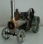
Lucky man, I do like those early machines, so much character and quality. Those conical ended tanks are great.
Looks late 20s - early 30s, is the engine a Villers MkVIII-C (147 cc)?. Hopefully one day I'll find something similar.
-
Ah, now with the pics you have posted, the mist is clearing and I see your problem (I think).
You are looking for a replacement Engine Breather pipe!, the Breather unit being the rectangular object on the right of your first picture.
The pipe fits between that box and onto the Carb (large Flo jet). The part number should be 280100 in the Part Manual which I believe supercedes to 692253 now .
If you search for either or both those numbers, you will find a screen full of choices price-wise and image comparison.
Also, my records show your engine to be allocated to 1984 W'horse B115 range, as the 1982 recorded date of your Tractor model shows engine 253707- 0209-01 ?.
Can check date of your engine with it's serial number. As you have a high mounted Fuel Tank and a vertical shaft engine, you don't always have a fuel pump fitted?.
Let us know when you're sorted.
Edit- @ 1716. The Tractor was actually built in 1981, scheduled build for Thursday 15th November, so the original engine would also have been 1981.
(Models/numbers changed around September when producing Model versions for the following year started).
-
I looked up the parts Manual for your engine on the B & S website and should work for you to download a copy of both - B & S Manual
So your Vac Hose part number is 393815 and is sold as a cut-to-size length.
As the Vac Pump has 1/4" diameter in/outlets, I would hazard a guess that modern spec 1/4" bore x 1/2" outer dia fuel pipe will be 'more-than-rigid' enough for the job.
Obtainable from the likes of Halfords. No sign of response on Ebay with the part number, but enter - briggs and stratton fuel hose 393815 into google and you'll be flooded with variations of responses (other search engines available).
-
1- Details are on page133/134. Wouldn't bother printing the whole Manual, just the bits you need for now, unless you really need some boring bedtime reading! .
2- Providing the bolts are cleaned up ok (heads and threads), you can reuse them. They are grade 8 (hardened/tempered) should have 6 radiating lines on the heads.
If you have removed, pushed them through a piece of card with their position noted, you can swap the bolts from the hot side of the engine to the cool side & V Versa.
If you haven't, be careful to check the lengths of them, as I believe one should be 1/4" longer to fit the engine lift eye position which, if I recall correctly should be in number 1 bolt position on the sequence diagram?.
3- Plug the bolt holes below the surface level with oiled rag as mentioned before. Oiled rag over the lowered piston to catch dust, dirt etc.
Cylinder is cast iron, so you can have at it with a softish rotary wire brush to speed up the process. Watch for broken off wire strands in the bore area.
When you're done, you can vacuum or blast the top clean with air. Unscrew the rags from the holes with long nosed pliers or tweezers.
Uncover the piston and do that, then you're done, unless you plan to do the valves as well?.
-
To be honest, I would say you are there with it. Hopefully the new gasket rolled lip will sit in the same depression area remaining.
You have enough flat area for a gas tight joint now. The original pic of the head showing the blown gas leak areas, which I later showed and denoted (but forgot to explain) with green arrows are now fine.
There is just the chamber carbon deposit areas to finish back to bright and you're done with the C/head.
Nearly time to arm yourself with a torque wrench and bolt it down to the sequence in the manual.
-
B6L versus B6S . Both have the same heat range, but the B6S has the shorter reach (screw thread into C/head) which is only 3/8" and so would not be able to dissipate tip heat away and into the C/head.
B6L (correct equivalent to Champion RH10C) has a reach of 7/16", so more thread engagement in the C/head which will bring the heat dissipation rate back to where it should be for that part of the Spark Plug.
You have probably deduced that the lower the number on NGK Plugs, the hotter it runs (the plug that is, not the engine). Champion = higher the number, the hotter it runs.
As you/we will never know what conditions were when the previous owner was running it (with/without Filter etc), it is difficult to say.
For your situation, once you've got it back to how it should be with a good A/Filter and what you've done C/head & Carb-wise, it will run fine. Not burning Oil yet and will have efficient cooling.
-
Comparing what you started with, it looks a whole lot better. I have never seen one that badly distorted.
In an attempt to be practical and honest, I can't help thinking that it needs more done to prevent further leaks?, but I'm a pretty fussy over-cautious person.
If you stop there, call it a day and fit it, there is a risk it will leech gasses past the gasket to the two uppermost, red circled bolt holes. I can''t say what the level of risk is.
At least the head would not be distorted again when bolted down to spec (unless the cylinder gasket face is not flat).
I can't be sure but I think those 2 bolts go onto blind holes?, so may contain any further leaking, but will make it difficult to remove them in future.
The 3rd red circled hole with the black arrow carries the bolt which I believe sometimes breaks into the Exhaust outlet chamber. That looks like it would be ok, as you have a small, clean flat face between it and the head chamber.
I understand/admire your self disciplined, marathon efforts to get to this stage, but it's your call really.
Maybe if you could continue at least to the point of obtaining a flat 'land' on the chamber side of those two top circled bolt holes?.
It may help if you place the head down on the paper and presuming you are right handed, place the palm of your hand (ball of your thumb) over the Spark Plug hole area, you can apply slightly more pressure to that area and less over the opposite end. You would emphasise more localised metal removal that way and still achieve flatness.
I don't think there is any issue with Valve (lift) Head clearance as a result of metal removal, but it would be worth checking anyway.
Just wondering if you have obtained/downloaded a copy of the K series Engine Service Manual?. It's very helpful.
Keep at it, you'll be rewarded with a better running Kohler in the end.
-
Yep!, and just to embelish what Norm says, the basic rules are - always use a metal that is the same as, or softer than the parent metal (unless you are very careful).
Hard Carbon can be removed easier after soaking with various types of oil. I use an old brand called Redex, but even WD40 will assist it.
The added advantage of this is that the bits of Carbon will stick together and to the scraper, rather than fall down gap like the side of the piston.
I found bringing the piston to top dead centre. Cutting a strip of card that is just thin enough to fit down around the side of the piston.
The length of the strip depends on the piston diameter. In your case, it needs to be almost exactly 300mm long and probably 7mm wide.
Clean gap out first with a piece of pointed plastic of the same thickness. Add engine oil to the gap around the piston and set the cardboard down around the gap.
This will stop most of the carbon rubbish being trapped there while cleaning the piston crown off.
I stuffed pieces of rag into the bolt holes and removed afterwards. Clean the cylinder gasket face and valve area first, then do the piston crown last.
Clean the piston, then remove the cardboard with any bits still stuck to it. Wipe area again with a lightly oil moistened lint free rag. Add oil around the gap again.
Lower the piston in the cylinder and wipe any remaining bits of oil/carbon away. Re-assemble.
Just a note on your point ref the worn throttle shaft, yes it can be a running issue, but it's affects are assuming that-
-the Air Filter is new and not clogged.
-the Carb is at least set to the correct preliminary settings and the ignition is correctly set. Only then will the engine be running lean with extra air.
It will also run hotter, which will show up on the exhaust valve colouring. In your case the exhaust valve is black which indicates running rich.
I suspect your Air Filter is not new, as the extra air through the throttle shaft is being compensated by the lack of it through the filter making the mixture rich.
Hope I explained that clearly for you.
Good luck and let us know how you get on.
-
Nice big shed there. Should have that filled 'in the blink of an eye'
I considered my Garage door security last year. No fixings or handles on the outside now.
It's a 1962 wooden Westland of Yeovil door, to which I added wire mesh in the recesses (anti chainsaw). Then filled with insulation.
Have 2 x 12" Brenton Bolts (plus the latch) on the top and 2 x 15mm Drop Bolts into concrete on the bottom. The sides are restrained by the heavy steel (anti saw) channel guides.
Major improvement to the temperature stability after draught proofing. Internal side access shows the FD60 rated Fire door, seals and Insurance approved Yale lock.
Feel much happier now, as it's integral on the ground floor-
Boosted the fire warning system and extingishers too.
-
This Gasket looks perfectly serviceable as an example (others are available)- K341 .
Someone has de-coked that in the not-too-distant past and may not have checked the flatness before refitting, or bolted it down in the wrong sequence and torque setting.
Clearly burning fuel at a rich setting, as the exhaust valve should be pale fawn/white colour. The good news is, it is not yet burning any oil from worn rings or cylinder.
You should not have a problem cleaning the face up on the head. It's quite straight forward.
Just take it slow and let the weight of the head sit on the W or D paper when circulating it. You can use a P320 grade or P240 if it's rough to start, then progress to finer grades.
No need to press down hard on it.
Use a brush to clean the dust out of the paper regularly (use a mask). If you find it hard to tell the high/low spots, use a coloured felt tip pen to highlight them.
I had to learn and have done all my engines that way, even if they didn't need it. I had to start with examples like this-
to this-
Done properly, you won't need to revisit it after.
|
|