| |
-
Been a while since I worked on this. Weather extremes have delayed setting up for paint preparation etc.
Managed to finish the 4 tiny 1/4" square lidded Oil Boxes which was a 'Jewellers Job' Silver Soldering the tiny hinge tubes in place. The hinge pins are 0.5mm hard wire.
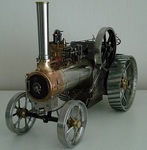
The one in the picture is of the R/H 3rd Shaft, where I had to work around the standard bearing design and the additional steam valve I made and fitted there.
The Oil Box is linked to the bearing by a short 1/16" dia copper tube. proper hex head bolts will be used in final assembly
All the other Oil boxes not shown fit directly into their respective bearings-
Changed the upper Steering Shaft bearing design with a more correct style version out of Gunmetal.
Also fabricated and added the Tool tray on inside of the Hornplate to hide the dowel end of the steering shaft bearing. Steering shaft is 5/32" dia (nearly 4mm) -
So till plodding on with this when opportunity arises.
-
Close with the Hydro Drive Belt. The number for that is 114895-
If he needs one of those, then if it was mine, I would look to get an OEM Belt, irrespective of cost.
114895 is type HB (in U.S. Toro list) which is Agricultural grade. 82.95 Inches length. 21/32" x 13/32". Metric equivalent/alternatives have minor dimension differences.
-
Very good comprehensive info provided Angus . 3 different belt sizes and 5 Deck versions to sift through without it.
Tractor is a 1989 ( 518-H was made in 88/89 only). Mower Deck is post 2000, and my records only go up to that date.
However, the preceding Deck number was 78345 (yep 42") and there is no indication from previous model number changes by year, that they altered the belt size.
This is confirmed by Toro online records using 78436 and the serial number.
So the 3 way check I made shows the Belt Number to be
102742, type 4L, 103 Inches in length.
Edit:- if they need the deck spindle drive belt number for the future, it is 6738. type 4L . 86 Inches in length.
-
I also reckon it's 81-10k801. 1978 C-101. Scheduled build date was Thursday 18th May going by the Julian date.
May only have a 3amp Alternator for Battery charging, as no lights fitted as optional extra?. May be lucky if 15amp Alt fitted.
Original Muffler, if not perforated is a bonus. 8 speed trans should be 103916 8 pinion Diff and should have the larger Woodruff Keys in the Axles.
Should be salvageable with some TLC. Well done.
Edit- correct day entered.
-
Thanks for the link Alan. Interesting. Ok January 2020 ! . Forgot about your Drummond . More use for the old set of Pre WW11 Whitworth spanners again then .
Was hoping to get over to Biddenden to see the Li'll 'D', no luck. Maybe next year when the Doc has sorted me out.
-
Very nice project Alan . Seems quite sound as far as condition. I like the bolt on Pulley extension to 3 speed changes.
Never heard of that make. Should be up and running by January then ! ........assuming a mild winter.
Hoping also to get a look at one, but fear it is way too big for me/my facilities, despite it also being a Treadle.
-
Looks like a productive garden . Is your soil chalk based, or sandy?. Looks very pale in areas.
That Hookworm is a species of Privet Hawk Moth (in UK), known in N/America as a Sphinx Moth. Can be up 5 inches Wingspan.
The hook is harmless, but can be whip like in movement reacting to attack.
-
I confess I did not check Ray's part number against the parts list, I just noted the lack of description to identify it.
Yes, Wristpin's number 505 (BS46 system) directly crosses to my 'hunch' number 6 on the (US) Chart I posted.
Here is a handy size chart that covers DN6888 metric and BS46 imperial comparisons. It is a link to a UK company, as I was unsure if I am allowed to put a company's document in the the Files section here. You can download your own copy though.
Woodruff Key Chart
-
Thanks gents, It was a challenge to clean and sweat the leaking joint areas without 'wicking out' the original solder, plus someone's previous attempts.
I'm impressed with how efficient it is at producing a single drop or a greater volume into the most awkward of Lathe points (even works upside down without leaking).
They're not common and worth a few quid now, but I won't part with it-
-
No problem Ray, I try to help anyone. So it's a bit beefier than I predicted. I have to assume due to the machine's age, it is Imperial and not Metric?.
Your measurements give 2 possibilities of Key size. I reckon it could be either one of nbr 6 or 8 in this handy size chart-
Best thing to do is check the depth of the keyway recess in the shaft and add the depth of the slot in the Backplate to get an idea of the Woodruff Key height.They are fairly cheap, so it may be worth ordering a couple of sizes close to your findings from here - Imp Woodruff Key to be sure of the right one (#6 would be my hunch).
The backplate slot width difference may well be due to wear.
Hope this helps, as I don't have any of those sizes.
-
I've been looking for a decent Oil Can that will serve my elderly Myford ML7 for some time. New quality pump oilers are not cheap, have unsuitable nozzles, or too big.
Much sought after, old quality ones like Braimes or some Westcos would do, but I stumbled over a little gem a few days ago and saved it from the bin.
I like to delve into history of items that I find and to my surprise, I find loads of it, so I'll include some here in case some may also be interested.
This is the Joseph Lucas Ltd No 40. 1/4 pint Oiler-
The pics are after I had to fully clean it out to a dry state due to joint damage/leaks around the Plunger - Body collar and the base of the spout.
Joints were cleaned out and re soldered.
This Oiler version is shown in a 1924 Advertisement that describes it's purpose as tool for use on small Cars and Cyclecars and sold for 7 shillings and 6 pence (37.1/2 new pence today).
There was also a bracket which you could purchase at the cost of 1 shilling (5 pence) to fit on the under bonnet (hood) bulkhead, or in the toolbox of the car to stow the Oiler safely.
Noted that some examples sold at Auto Auctioneers were claimed to be part of the Toolkit for Bentley, Rolls Royce etc!, but I suspect they would have been nickel plated if supplied to them.
The makers name is that of the Automotive Electrical suppliers of dynamos, lights, relays etc of recent years.
With the joint repairs done and cleaned up, I gave it just a light clean over the rest of it and had no intention of attempting to remove, clean the age scarring or dents.
The only real damage was the broken off threaded tip of the spout where, according to Lucas' info, it had a little cap screwed on the tip for whe not in use.
The tip being broken was not usable like this, so I managed to identify the thread form from the 2 remaining full threads and established it to be 1/8" Whitworth (40 threads per inch).
Spookily, Whitworth is the basis of the creation of the 'Model Engineer Series' thread form in 1909 and I have a set of those Taps and Dies, so sorted that issue.
Took some measurements and some hard Brass and made the parts as close to the original as poss, but not fussed with accuracy-
Soldered the tip in place-
So there it is. Even the original leather washers are still fine.
I'm always impressed with things that were made then, for example this can has the number 428 stamped on the handle as a production number and the base has a 'G' stamped in representing the individual who checked it for quality over 90 years ago.
Regards
-
I have never seen one of those, so have no idea what one looks like. Can only suggest you look at the Poulan Chainsaw Thread in Other Garden Machines and compare my images with your carb.
Usually, if there is no primer bulb, then it primes/supplies fuel using a vacuum diaphragm system in the carb.
-
I may have one, Can't remember the size now, but either a Nbr 3 or 5 woodruff. Should be 1/8" wide for a 3/4" dia shaft. Measure the keyway width in the shaft and the length for me and I'll check my stock.
-
Just wondering about the duration of this current dry spell the other day and I had to venture out yesterday.
I took the shady tree lined country road route, where I twigged that phenomenon of Summer Branch Drop is now occurring.
I suppose it was bound to happen, but has yet to become a real common and dangerous occurrence.
With the forecast only offering a brief respite over the next few days in my area (south eastern England), and maybe even some rain, it will get hotter again soon after for quite a while.
I've heard that some public events are being cancelled due to heat !. A shame, but understandable really.
It is really worth remembering that using trees as shade in this weather (in UK) is risky due to branch drop. I assume it can happen in other countries as well.
-
No real loss with that chain then, looked past serviceable to me. I was looking for the circumference measurement of the chain on the 2 fitted Sprockets, because, believe it or not, I may have just the thing to fit. I need to be sure it will fit without excessive stretch. At least you may have a last resort if the 'O' ring is unobtainable.
-
Would be handy to establish if the Engine output shaft/Pulley unit has a parallel shaft, or tapered, with a Keyway.
Certainly Mark's suggestion will add the advantage of some heat to create a difference between the 2 components, to improve separation.
-
Yeah !. You just wanted a bigger toy to drive really Mark . Must say it looks a real fun magnet and I hope you find many hours of fun work for it.
-
Glad it was enjoyable, good pics thanks. Shame it was over a hot weekend and lots of Sporty distractions on TV.
The British Anzani reminded me of one of the several challenges I'm being badgered with .
-
Just had another look at the second chain (on the Osprey). Have a look on the inside of the chain for the split retaining Cotter Ray, right next to the Cranked Link (half).
I think I was wrong and it is correct, as there are the right number of Links in that chain in total (53), so it may have been fitted on the inside edge.
Can't be sure, but I think the chain is 1/2" pitch and a new cottered connecting link is available, as well as chain if required.
-
They certainly have done a superb job on them. Noticed the White Mini Van must be an ongoing project. Missing Wipers...Very nice though. My favourite would be what look's like an MG TA ( Red) 2nd pic of 2nd batch. Nice Moggy Van by the way Andrew .
-
Yep!, Reckon that is another bodge to eliminate chain slack. May have fitted the half link in situ in consideration to the points mentioned in my PM regarding the Axle movement restrictions with Keyway and Circlip.
Other more experienced Members familiar with this model may offer more accurate/beneficial advice than I, but my opinion of the amount of slack in the chain is not of great significance. If you refer to the earlier image of 'Spot the Removable Link'. that amount of slack is not an issue in a correctly installed set up.
This is because there should be a large 'O' ring fitted around the Chain. My interpretation of the fitting of it is-
- to provide a retaining effect which prevents chain slap against the inside of the Cover Plate
- acts as a grease retainer
- maintains pressure to ensure chain engages teeth on the sprockets efficiently.
My bet is these are missing on both of your machines. If you can carefully measure the outer circumference of the chain/sprockets and post it on here please.
At this point, I am not sure of the availability of spare parts are for these, so here is a link for you to make enquiries about any parts we are discussing-
PARTS
Replacing bronze bushings should not be a problem, as most imperial sizes are still available.
Replacing the Clutch friction material as mentioned in PM-
The thickness was about 5-6mm Woven (probably 1/4" when new).
Not sure if you're buying sheet to cut your own, or having Autoandindustrial to precut for you?. I've shifted these images to this thread, rather than put links in to make it easier. If you're cutting your own, a junior hacksaw will work and lining is safe with no asbestos.
The diameter of the linings are slightly larger than the diameter of the plates either side to ensure even plate wear-
You should be able to assess measurements from this pic for the inner diameter cutout by comparison with your own plates.
Also gives an idea of the important clearance of the friction lining edge and the proximity of the chain. No grease must be allowed near the lining-
Hope this helps and keep at it.
-
Great pics, thanks. Noticed there is also a trend of creating 105E Pickups (Anglias). White Minivan reminds me of my first car.
-
Yes Norm, on Thurs 5th Jul, I believe that was the last known one and of the greatest magnitude. Unusual around here, At least the Wine n Spirit store is intact
-
I wondered why I had found my Fluorescent garage/workshop light had parted company with the ceiling and hanging on the cable ties when I got back from shopping last Thursday?.
Also found 2 empty cans had fallen off the shelf edge. The light was well fitted only recently.
Today, I was told we had had an Earth Tremor again !. Yeah right I thought,...... until I was advised to check the BBC news website - Surrey Shaker .
-
It's a bodge Ray. Have a look through this Thread for pics of what it should look like OSPREY.
I've sent you a copy of the Manual which should cover it (via PM)
As for the link in the chain, I think I see it arrowed here -
Open end is usually on the trailing side of rotation .
You'll probably need to obtain and bond new friction pads onto the Toothed Clutch Plate.
A link to the people I've used in the past if it helps- Friction .
Bonding them well requires scrupulous cleaning and a good bonding resin like Araldite Original ( NOT the 5 min stuff).
I'm sure Wristpin, Nigel and others will offer more experienced options and advice on that and the machine.
Edit in RED
|
|